
Recommended
Recommended
More Related Content
What's hot
What's hot (20)
Viewers also liked
Viewers also liked (17)
Similar to H5243740
Similar to H5243740 (20)
More from IOSR-JEN
Recently uploaded
Recently uploaded (20)
H5243740
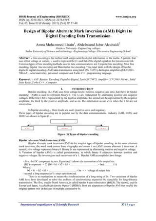
- 1. IOSR Journal of Engineering (IOSRJEN) www.iosrjen.org ISSN (e): 2250-3021, ISSN (p): 2278-8719 Vol. 05, Issue 02 (February. 2015), ||V4|| PP 37-40 International organization of Scientific Research 37 | P a g e Design of Bipolar Alternate Mark Inversion (AMI) Digital to Digital Encoding Data Transmission Amna Mohammed Elzain1 , Abdelrasoul Jabar Alzubaidi2 Alazhery University- Engineering colleges Sudan University of Science and technology –Engineering College- Electronics Engineering School Abstract: - Line encoding is the method used to represent the digital information on the media. A pattern, that uses either voltage or current, is used to represent the (1s and 0s) of the digital signal on the transmission link. Common types of line encoding methods used in data communications are: Unipolar line encoding, Polar line encoding, bipolar line encoding and Manchester line encoding. This paper deals with the design of bipolar digital to digital encoding (AMI) data transmission using latch (SN 74373), darlington amplifiers (ULN 2003- 500 mA) , solid state relay, personnel computer and Turbo C++ programming language. Keywords: - AMI ,Bipolar, Encoding, Digital to Digital, Latch SN 74373, Amplifier ULN 2003-500 mA, Solid State Relay ,Turbo C++ , Computer. I. INTRODUCTION Bipolar encoding, like AMI, uses three voltage levels: positive, negative, and zero. Zero level in bipolar encoding (AMI) is used to represent binary 0. The 1s are represented by alternating positive and negative voltages. If the first 1 bit is represented by the positive amplitude, the second will be represented by the negative amplitude, the third by the positive amplitude, and so on. This alternation occurs even when the 1 bit are not consecutive. In bipolar encoding, , three levels are used (positive, zero, and negative). Three types of bipolar encoding are in popular use by the data communications industry (AMI, B8ZS, and HDB3) as shown in figure (1).. Figure (1) Types of bipolar encoding Bipolar Alternate Mark Inversion (AMI): Bipolar alternate mark inversion (AMI) is the simplest type of bipolar encoding. in the name alternate mark inversion, the word mark comes from telegraphy and means 1 so (AMI) means alternate 1 inversion. A neutral, zero voltage represents binary 0. Binary 1s are represented by alternating positive and negative voltage. A Variation of bipolar (AMI) is called pseudoternary, in which binary 0 alternates between positive and negative voltages. By inverting on each occurrence of a 1. Bipolar AMI accomplishes two things: - first, the DC component is zero. Equation (1) shows the summation of the output bits. (DC)component = Σ (b0 + b1 + b2 + b3 + …………………………..+ bn) ………. (1) Where; b0 + b1 + b2 + b3 + …………………………..+ bn = > voltage of output bits - second, a long sequence of 1s stays synchronized. There is no mechanism to ensure the synchronization of a long string of 0s. Two variations of bipolar AMI have been developed to solve the problem of synchronizing sequential 0s, especially for long-distance transmission. The first, used in North America, is called bipolar 8-zero substitution (B8ZS). The second, used in Europe and Japan, is called high-density bipolar 3 (HDB3). Both are adaptations of bipolar AMI that modify the original pattern only in the case of multiple consecutive 0s. Bipolar HDB3B8ZSAMI
- 2. Design of Bipolar Alternate Mark Inversion (AMI) Digital to Digital Encoding Data Transmission International organization of Scientific Research 38 | P a g e Figure (2) Bipolar AMI encoding II. METHODOLOGY The circuit diagram for the method of bipolar digital to digital encoding data transmission (AMI) consists of two elements (hardware and software): A . Hardware components: Latch SN74373: used as a buffer to store data. Amplifier ULN 2003-500 m A : used to increase the current of the signal. Solid state Relay: used as an ON-OFF control device. Lablink: used to connect latch SN 74373 to the computer. Computer: used to install Turbo C++ programming language. B. Software: Turbo C++programming language: is used to send data bits to the designed circuit. The circuit diagram for the paper consists of latch SN 74373, Darlington amplifiers ULN 2003-500 m A, double contacts solid state relay, computer and Turbo C++ programming language. The block diagram for the design is shown in Figure (3). The method is based on creating an input digital data by the computer. One bit to pass through the interface each time. The output depends upon the input bit value. This process will be repeated until the end of data. Data source computer Bits Interface Bipolar dig. To dig. Encod.(AMI) Figure (3) Block diagram of the return to zero bipolar digital to digital encoding circuit. III. ALGORITHM The computer algorithm includes a sequence of steps for the performance of bipolar digital to digital encoding (AMI) . Turbo C++ language is used for programming the computer . Each byte will be send serially bit by bit to the interface circuit . The first stage in the interface circuit is just to store the bit .The second stage in the interface circuit is to amplify the current up to (500 mA.). This current is sufficient to drive the solid state relay .Data from the computer are generated byte by byte .A star (*) is assumed as the end byte of data..The software contains the main program plus one subroutine for the AMI encoding .The algorithm is : Latch Darlington Amplifier +5 volts output -5 volts
- 3. Design of Bipolar Alternate Mark Inversion (AMI) Digital to Digital Encoding Data Transmission International organization of Scientific Research 39 | P a g e START Initialization: --- Clear the output to start the encoding. ---- Generate clock frequency. Enter byte: --- If ( byte entered = * ) go to end. --- Call AMI encoding subroutine. Check end of byte: --- If ( bits counter = 0 ) ,then go to enter byte. END AMI encoding: (Subroutine): Declare a variable: Flag = +5 volt. Bits counter = 8. Check bit: --- If (bit value = zero), then put the (SSR) to 0 volt position and go to check the clock. --- If (bit value = one), then go to check the flag value. Check the clock: --- If a clock duration ends ,then decrement( bit counter) and go to check bit value. --- Else go to check the clock. Check the flag: --- If (flag = +5 volt), then put the (SSR) to position (- 5 volt) and make (flag =.-5 volt). Go to check the clock. --- If (flag = -5 volt), then put the (SSR) to position (+ 5 volt) and make (flag =.+5 volt). Go to check the clock. Return IV. RESULTS The circuit for bipolar digital to digital encoding consists of an interface circuit which contains ;latch SN 74373, amplifier ULN 2003-500 m A, solid state relay, computer and Turbo C++ programming language .The task of the interface circuit is to transform the solid state relay (SSR) from one state to another .The change over position of the SSR depends upon the value of the incoming bit .The final output from the interface circuit will be a signal voltage that varies according to the bit value. Table (1) shows the result of bipolar digital to digital encoding (AMI). Table (1) Bipolar digital to digital encoding (AMI) Bit value Latch output SSR Position (volts) Output (volts) 0 0 0 volt 0 volt 1 1 + 5 volt + 5 volt 0 0 0 volt 0 volt 0 0 0 volt 0 volt 1 1 - 5 volt - 5 volt 1 1 + 5 volt + 5 volt 1 1 - 5 volt - 5 volt 0 0 0 volt 0 volt V. CONCLUSION The bipolar digital to digital encoding scheme (AMI) offers synchronization for logic one between the transmission and reception entities. The other advantage is that the AMI encoding scheme eliminates the dc component in the output. Successive alternations in the polarity for logic one is to avoid the dc component .The circuit can be easily modified to accommodate other digital to digital encoding schemes. The software is programmed to be user friendly . The user has to enter the data from the keyboard of the computer byte by byte till the end of data .
- 4. Design of Bipolar Alternate Mark Inversion (AMI) Digital to Digital Encoding Data Transmission International organization of Scientific Research 40 | P a g e REFERENCES [1]. Behrouz A. Ferozane, Data communications and networking, The McGraw-Hill publishing company limited, 2003. [2]. William Stalling ,Computer Data communications and networking , The McGraw-Hill publishing company limited,2007 . [3]. Morris Mano ,Digital design , The McGraw-Hill publishing company limited,2004 . [4]. Douglas E. Comer , Computer networks and internet, The Prentice Hall Inc.,1999 . [5]. http://wiki.answers.com/Q/Definition_of_digital_signal_encoding#slide=2 [6]. http://ecomputernotes.com/computernetworkingnotes/communication-networks/encoding-techniques- and-codec [7]. http://encyclopedia2.thefreedictionary.com/Manchester+encoding [8]. http://en.wikipedia.org/wiki/Bipolar_encoding#cite_note-1