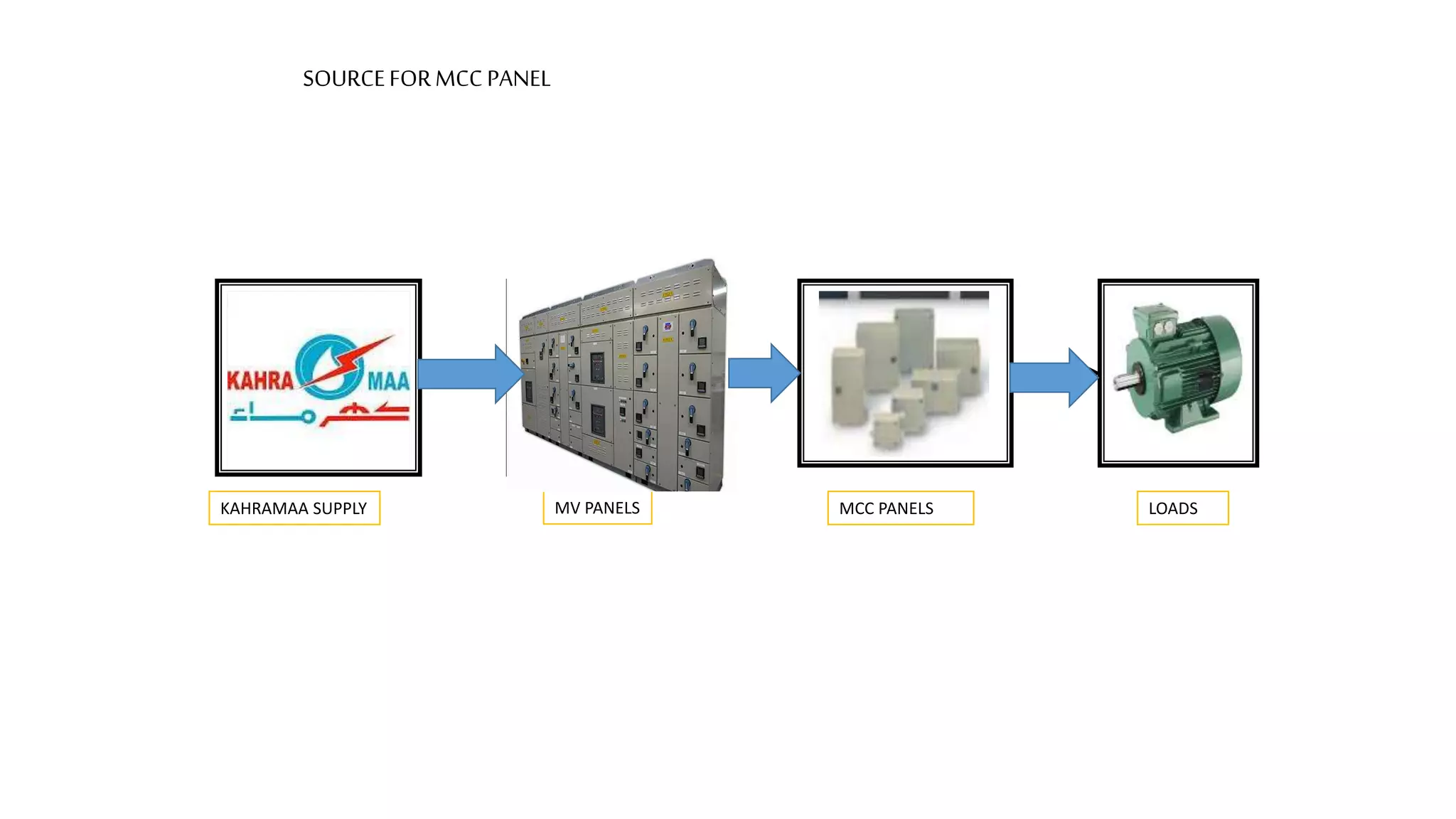
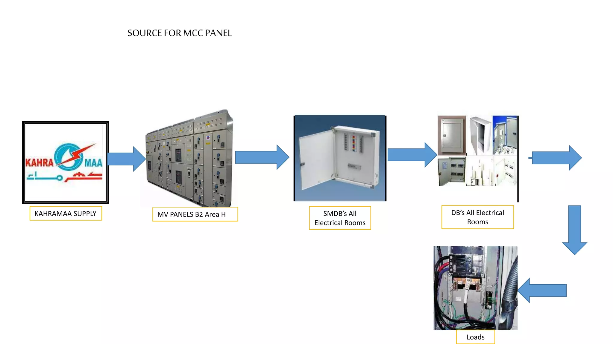
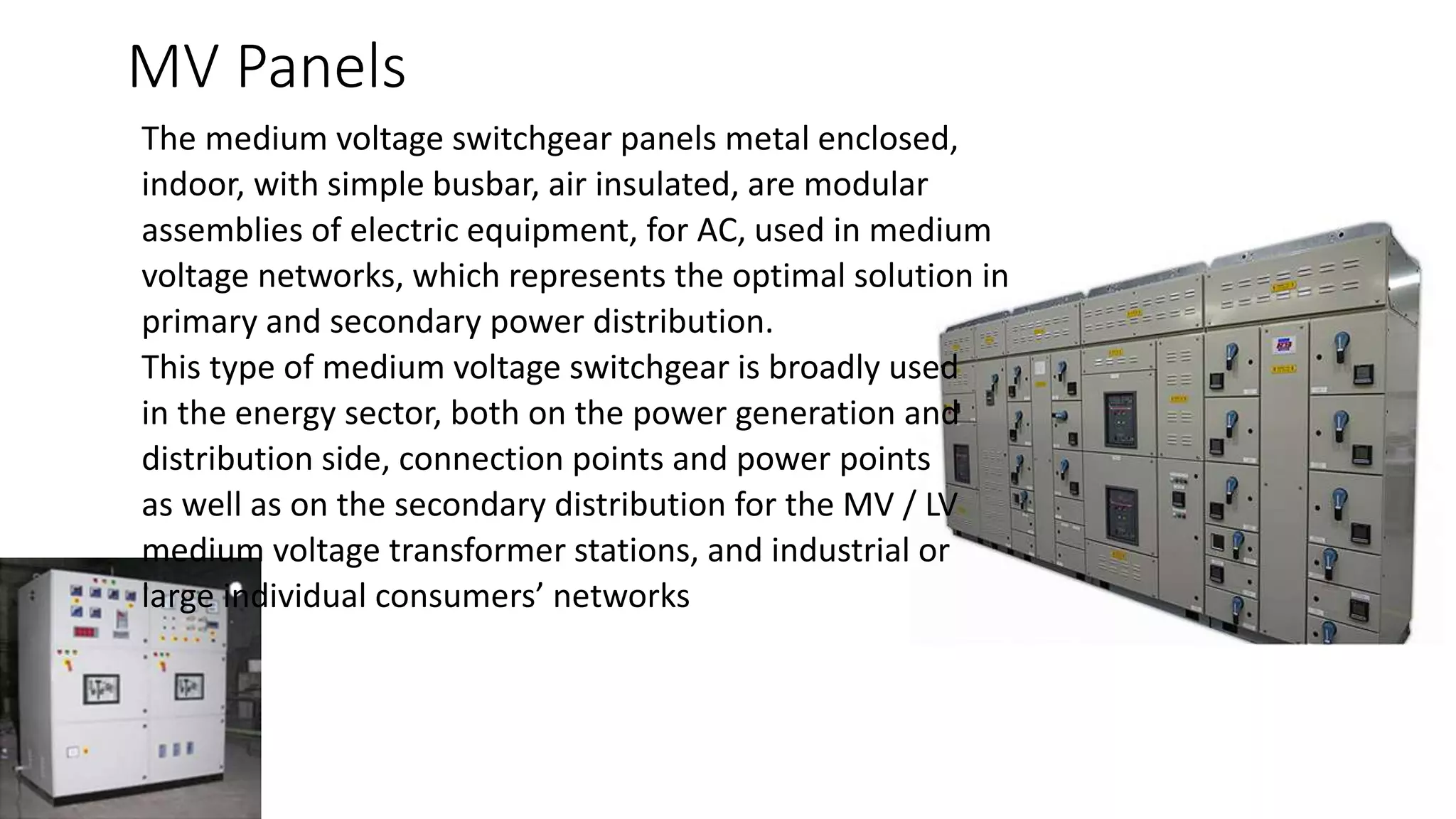
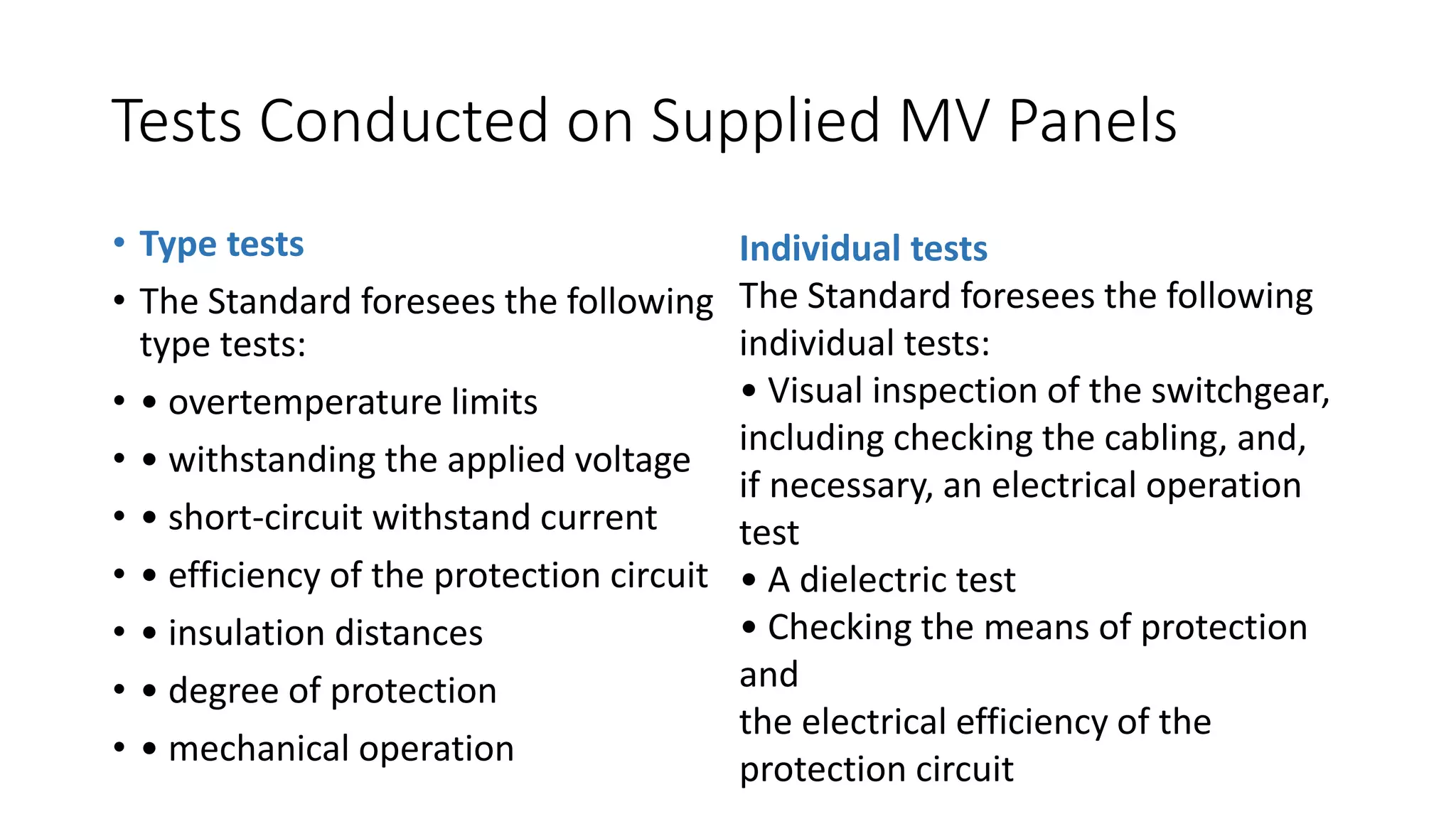
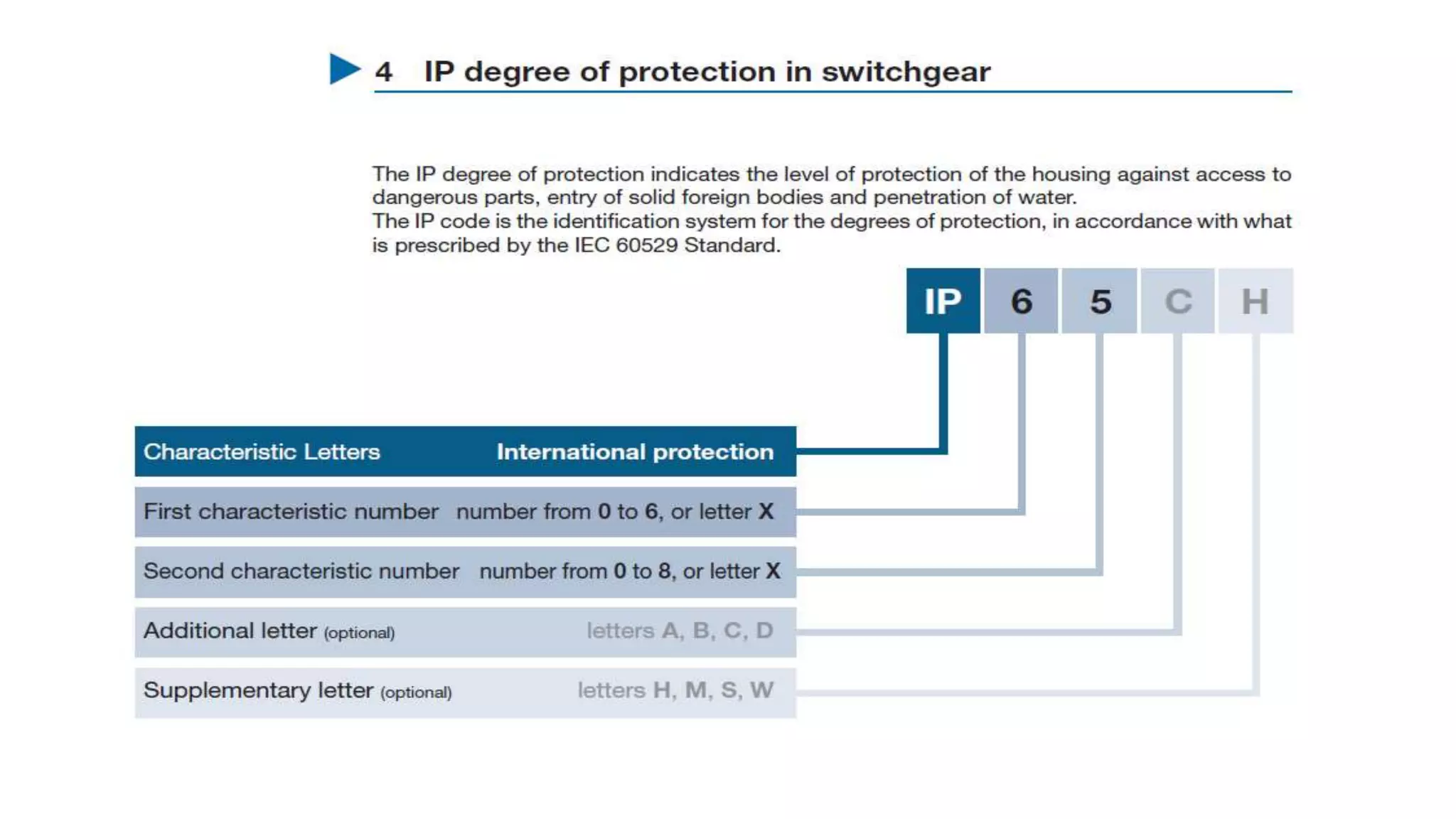
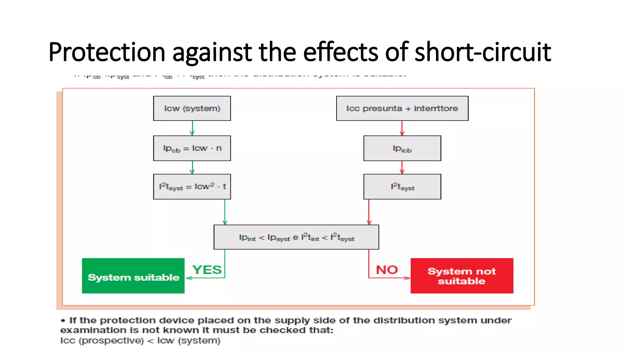
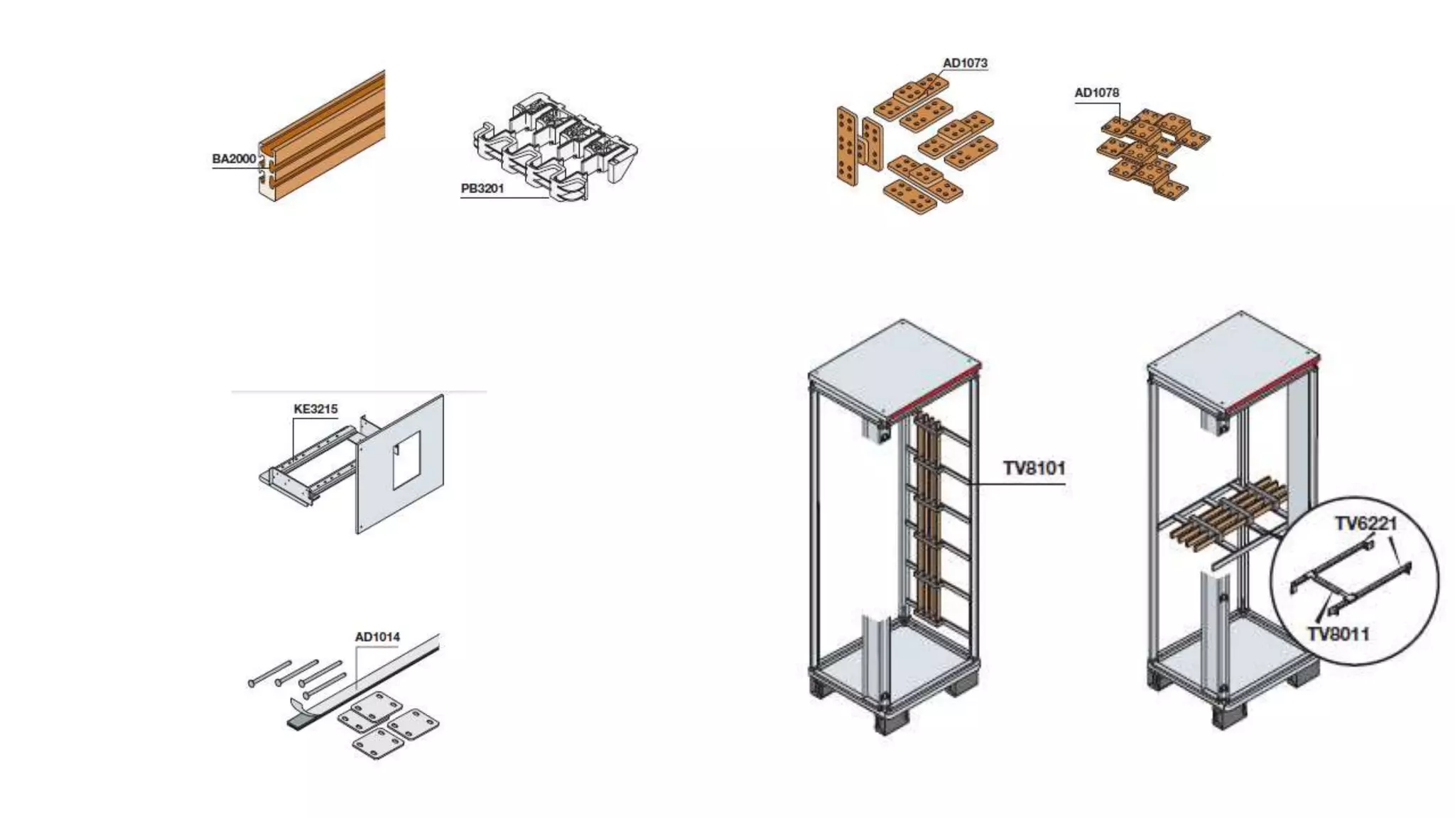
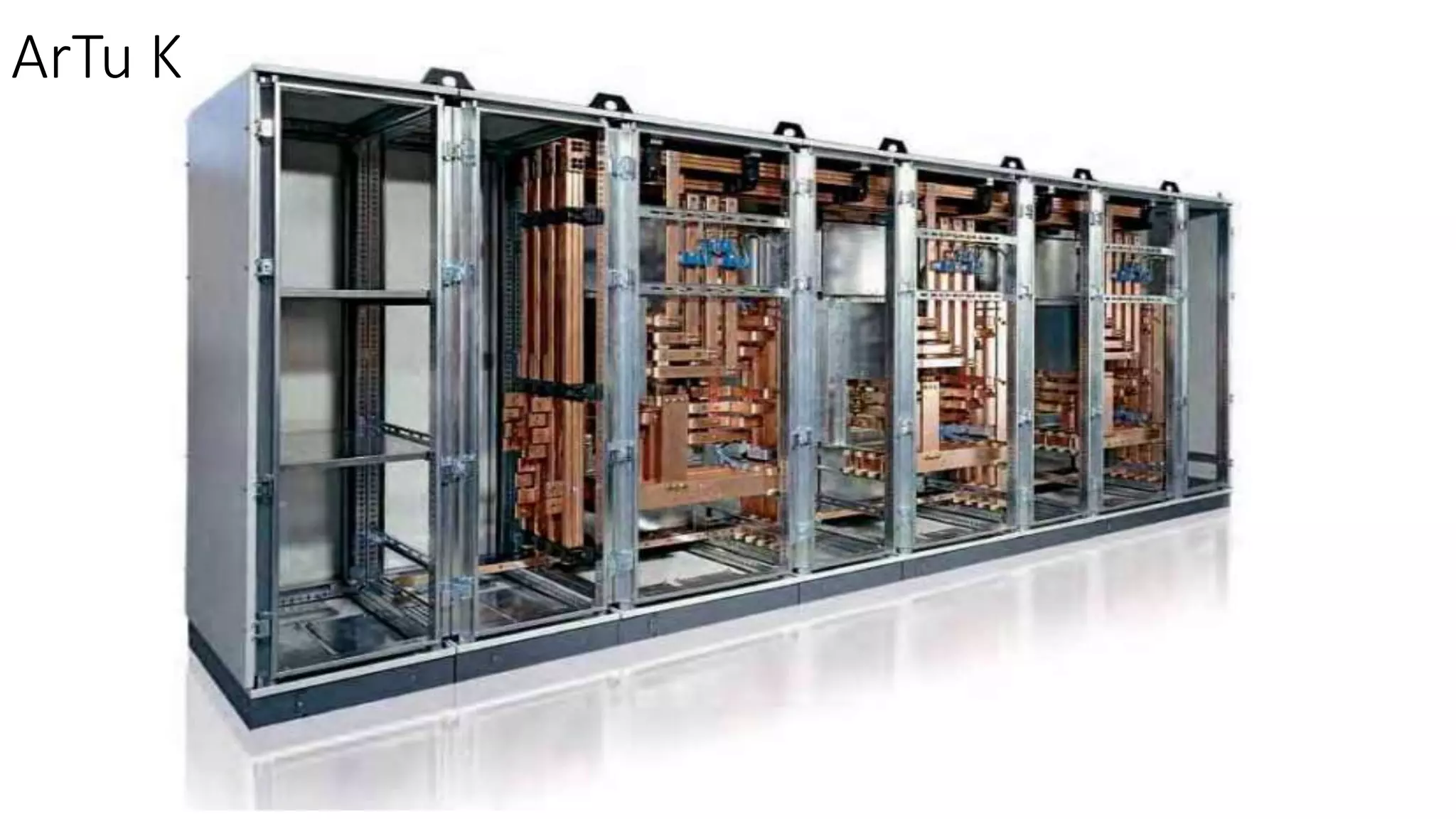
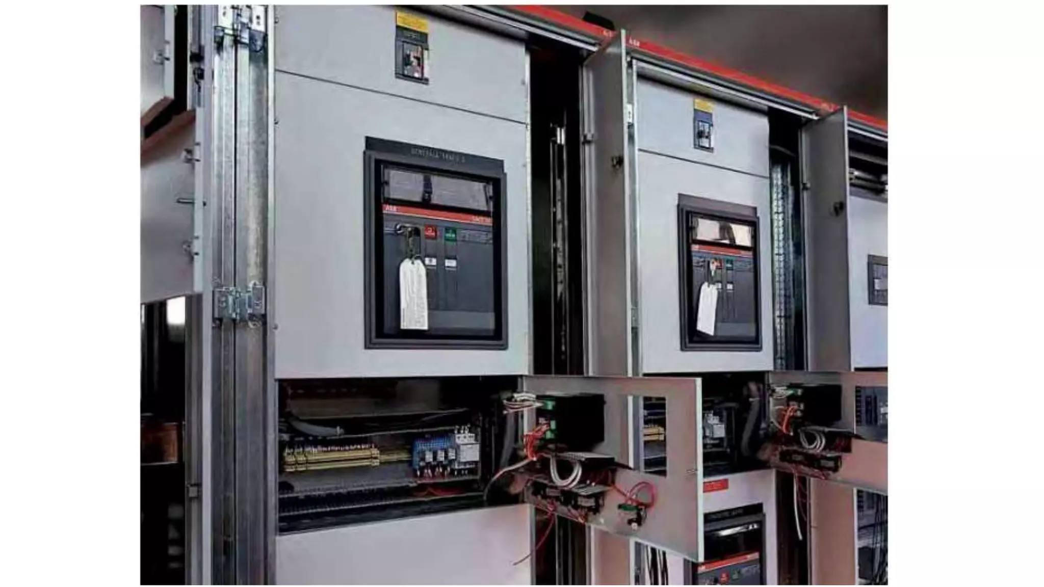
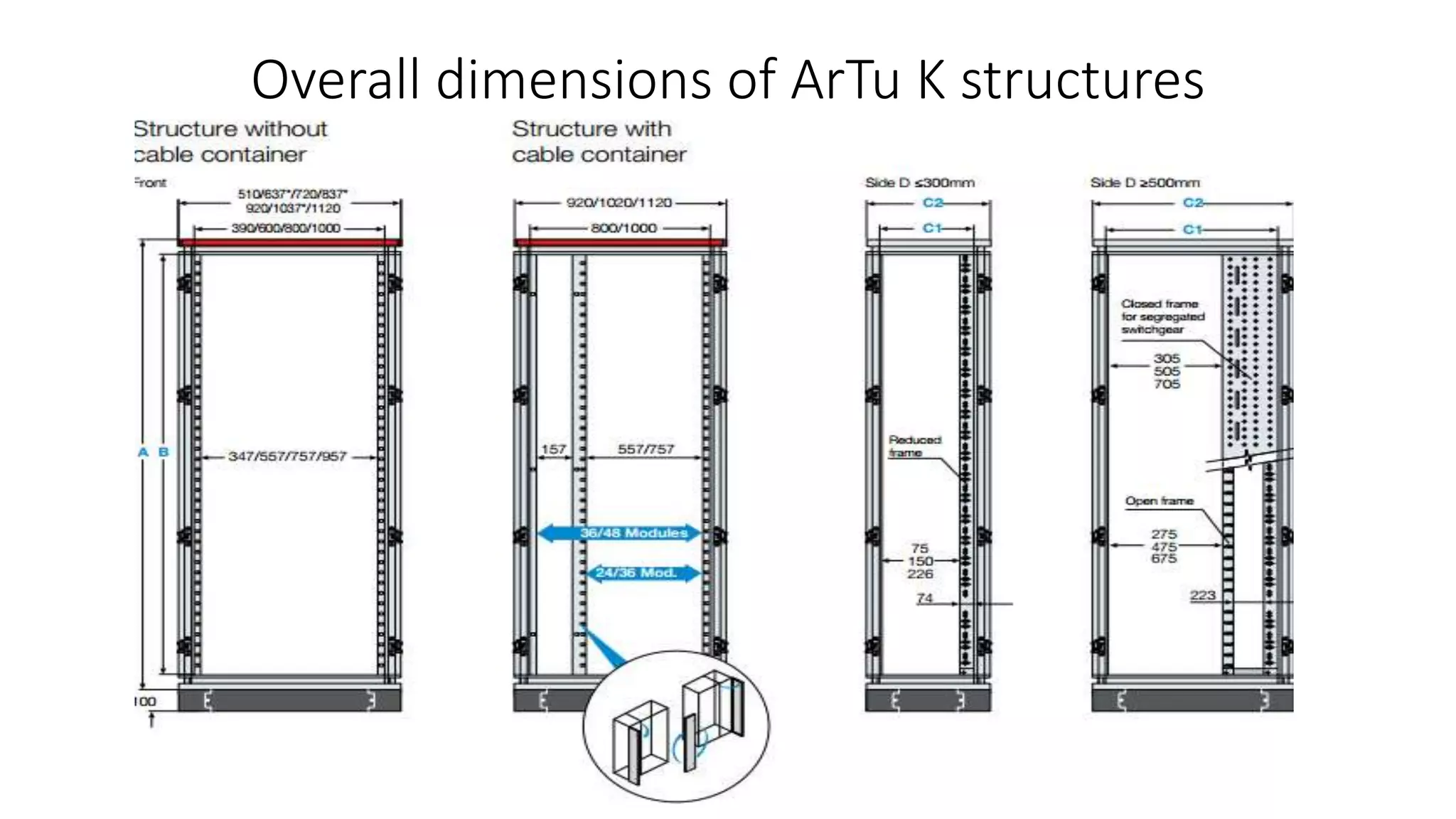
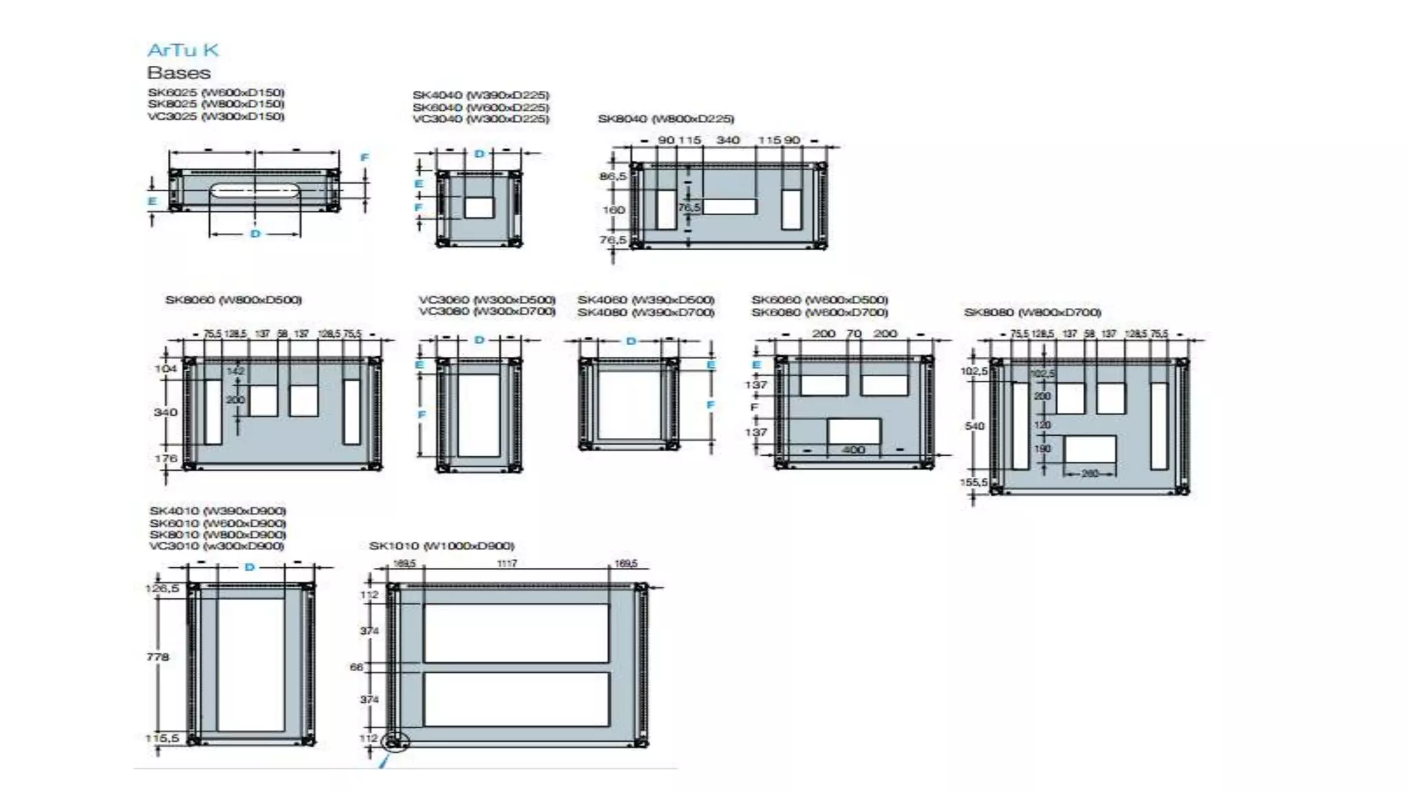
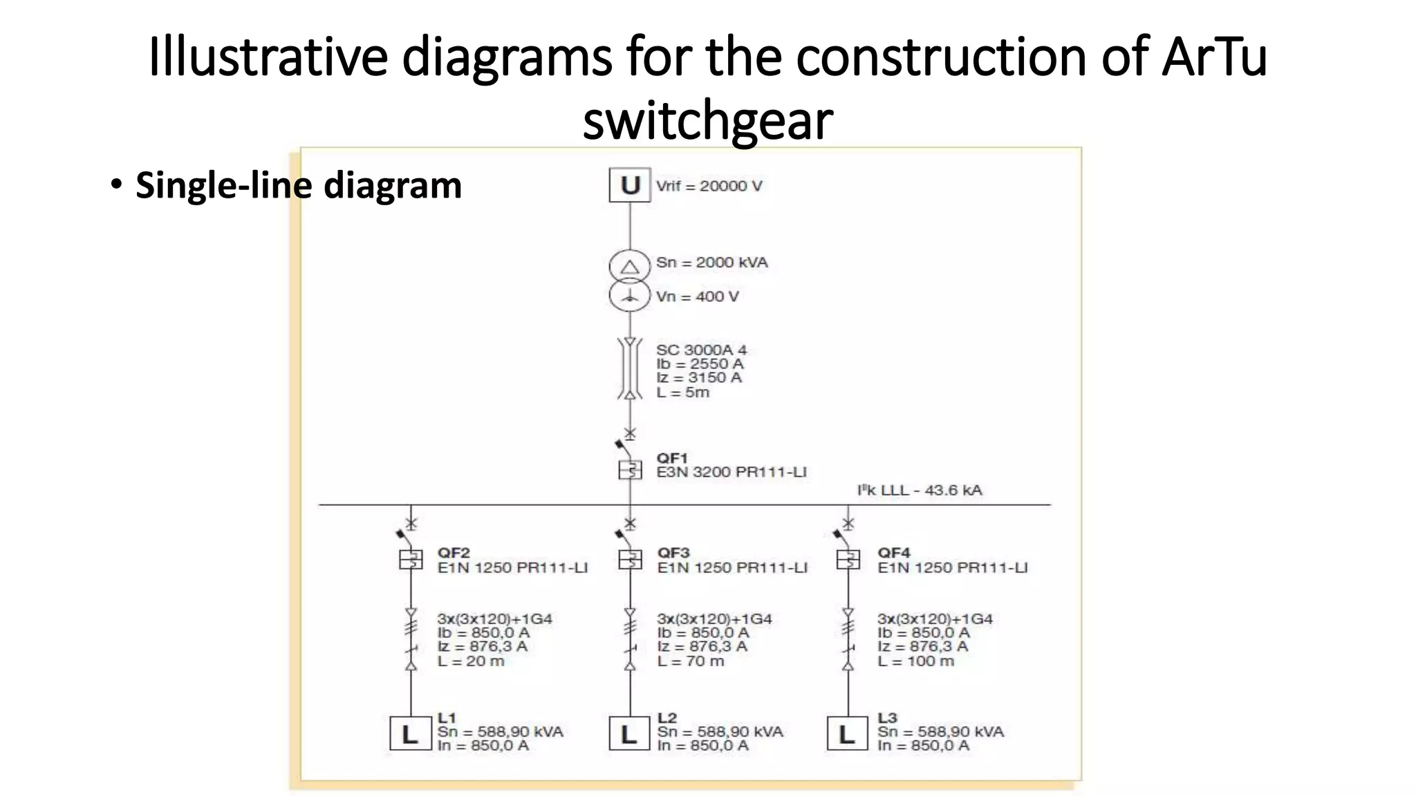
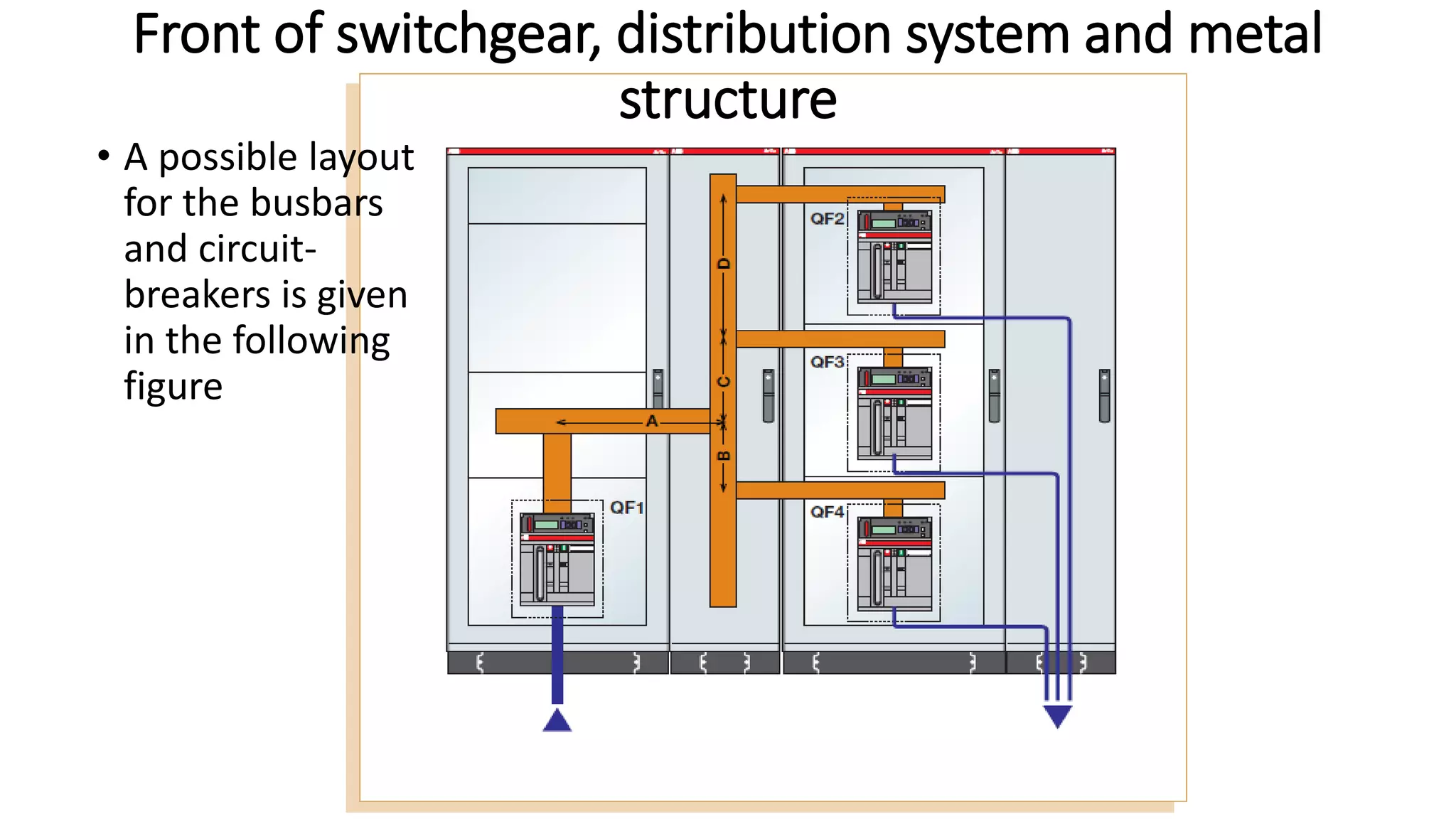
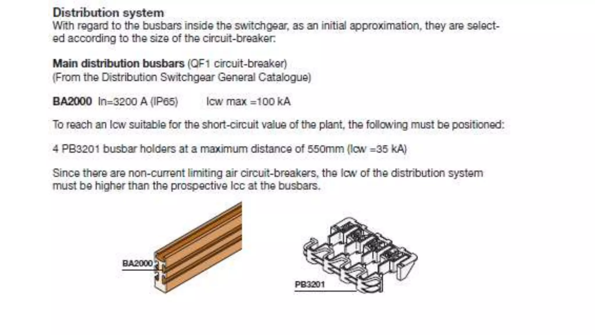
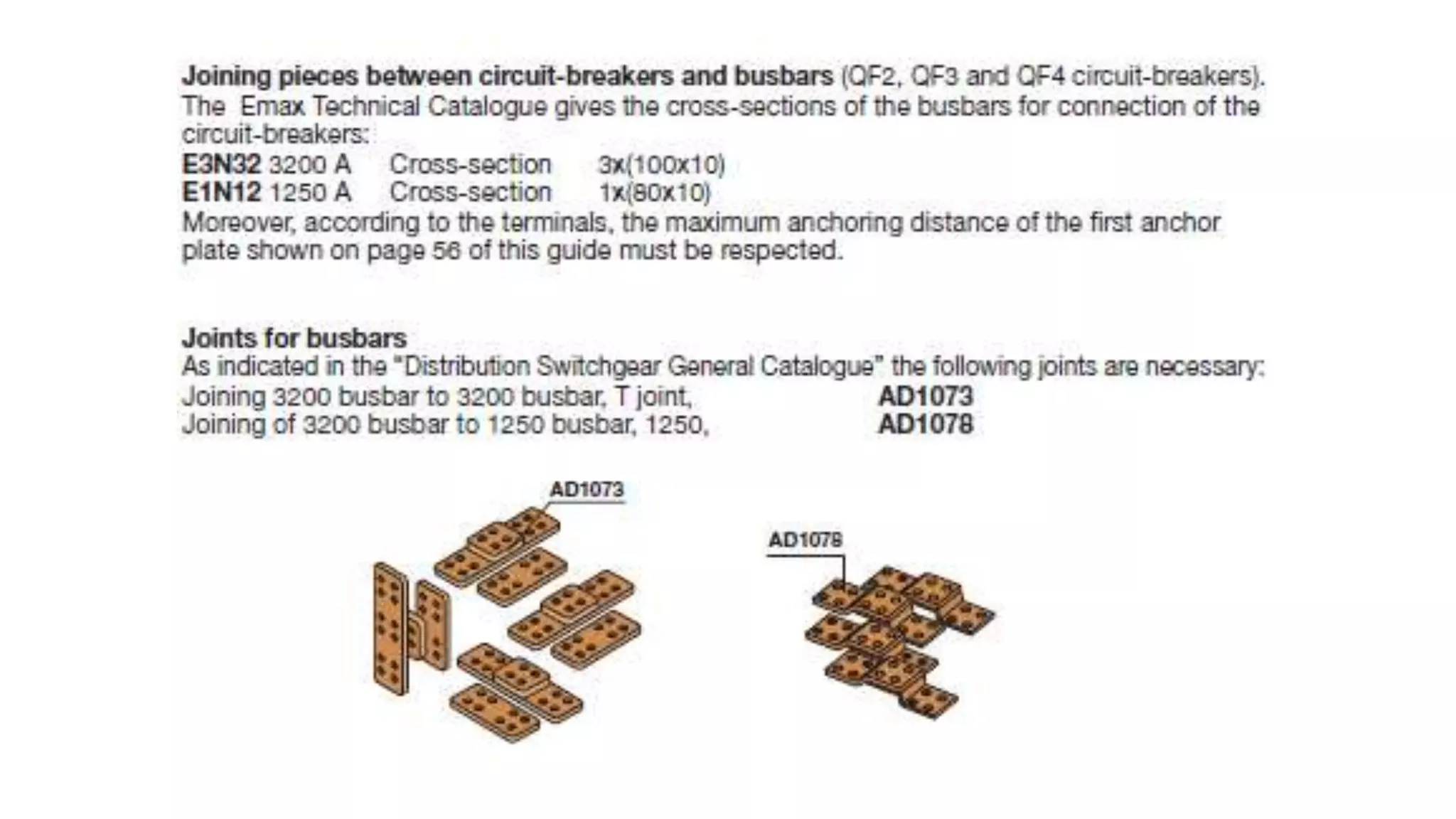
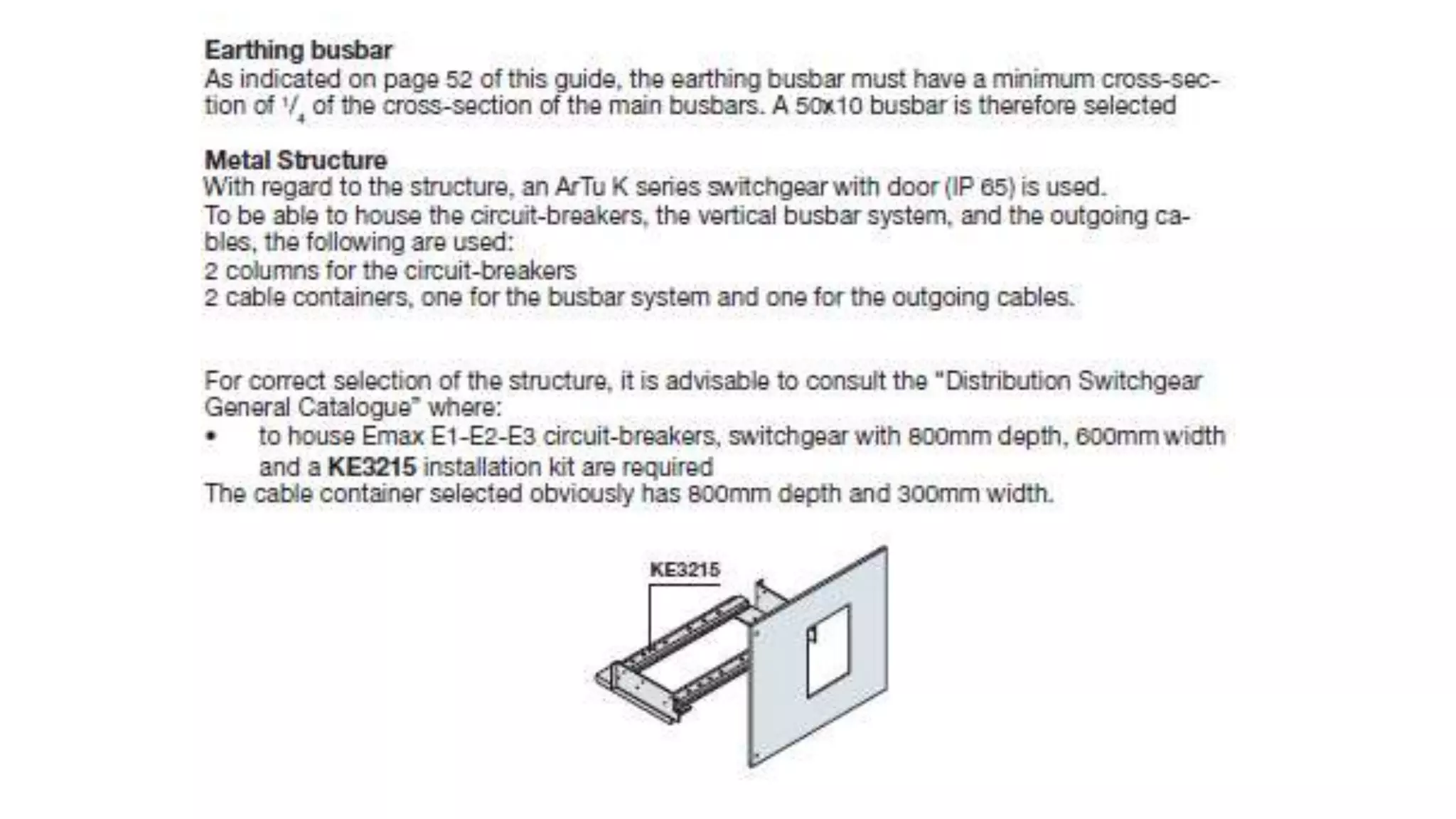
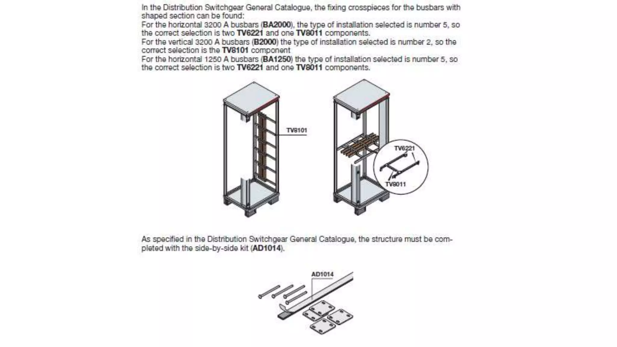
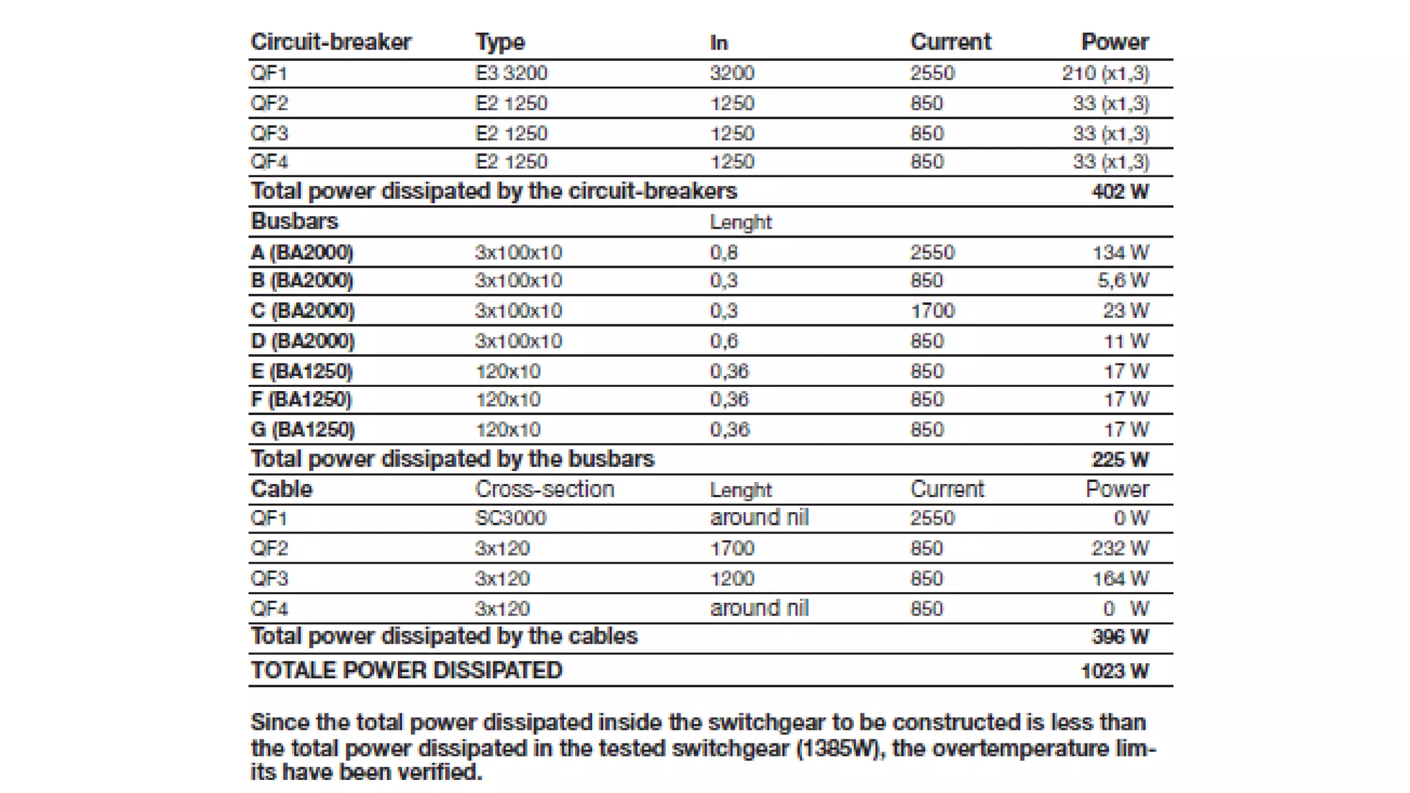
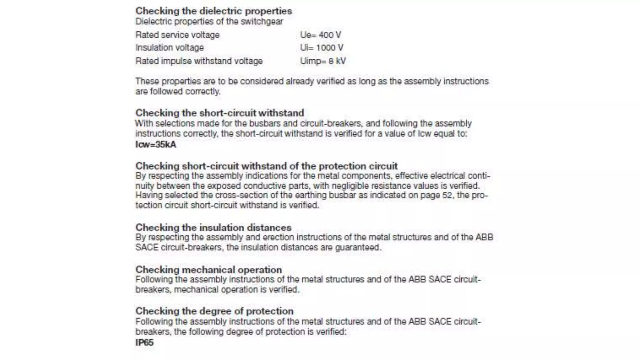
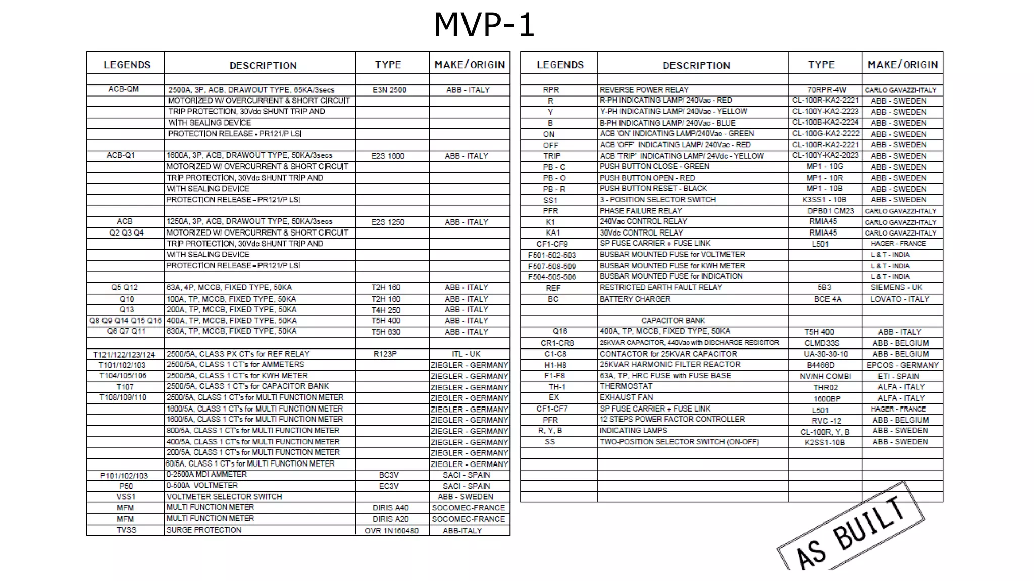
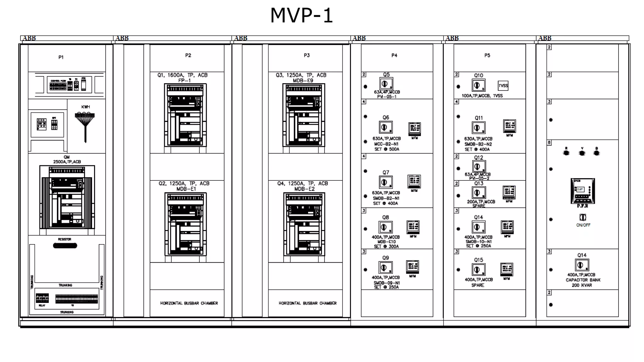
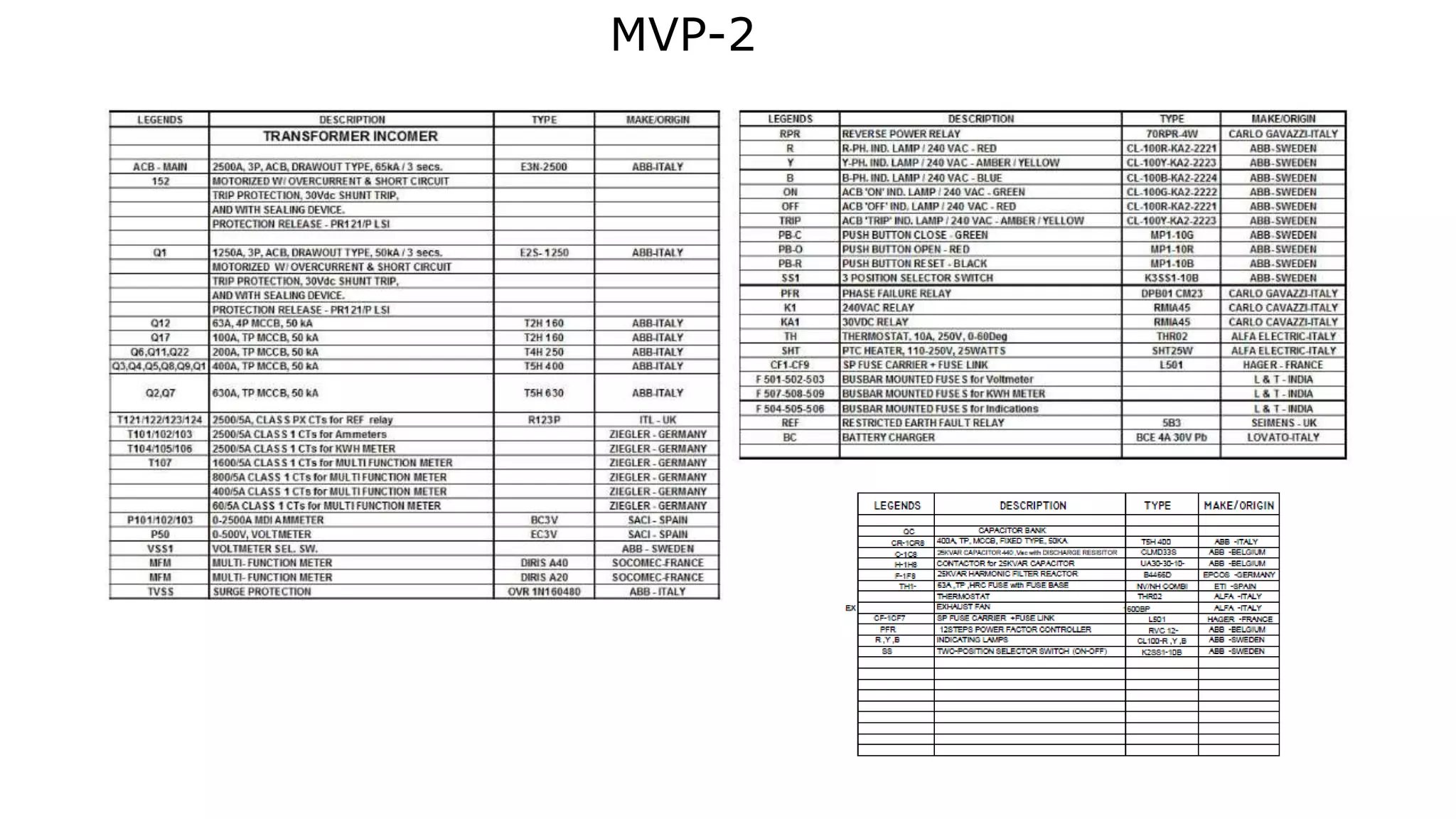
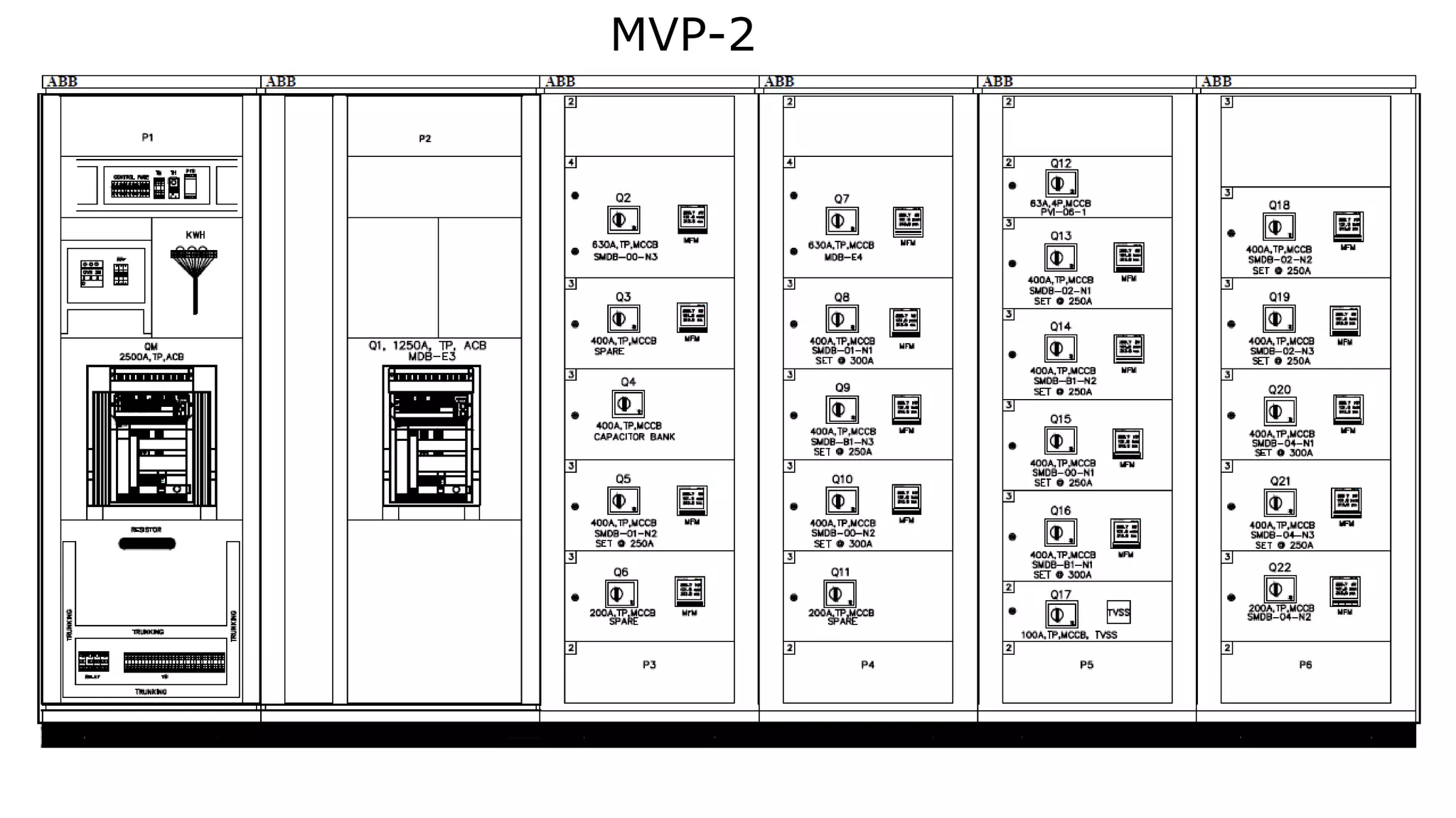
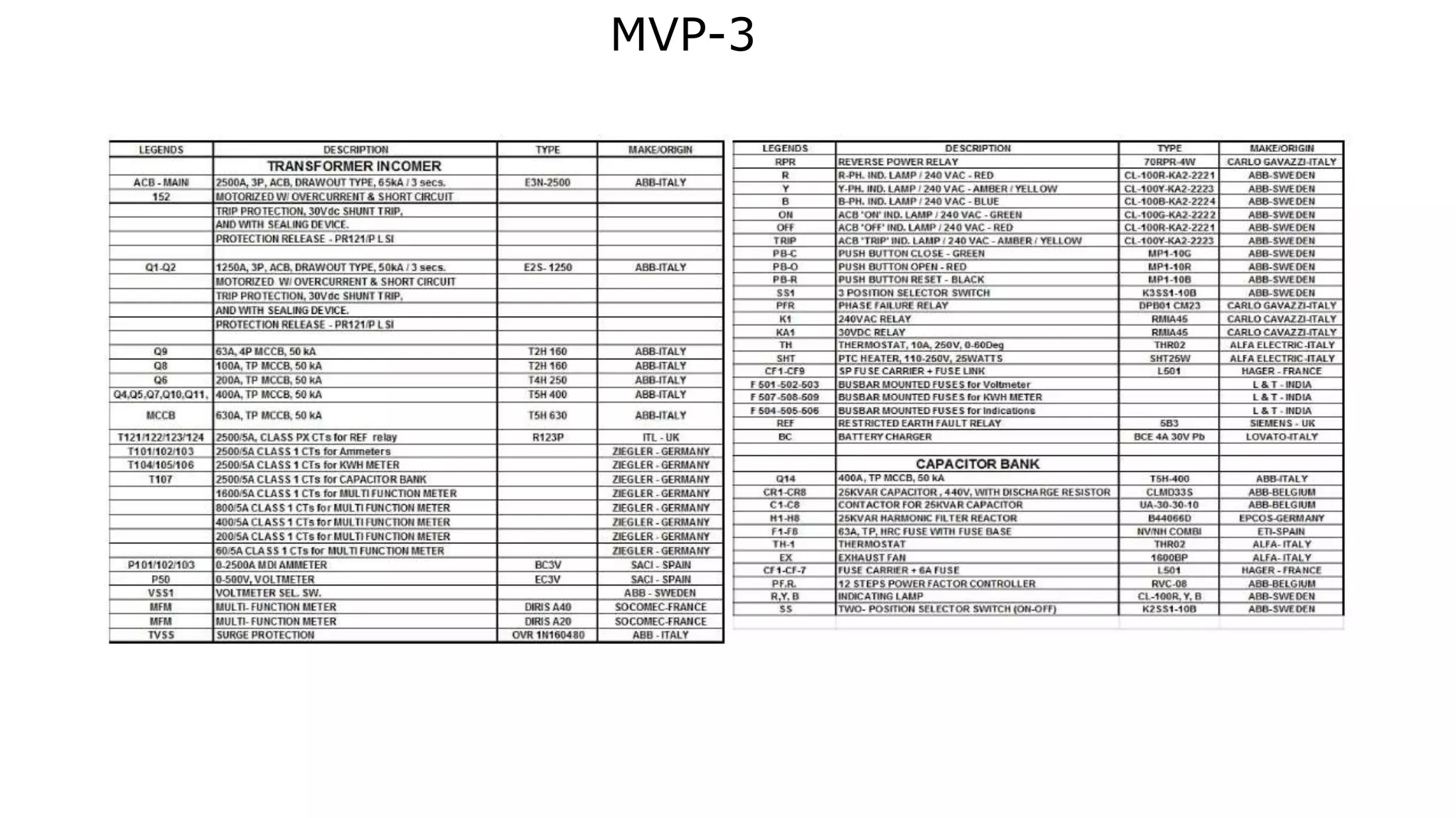
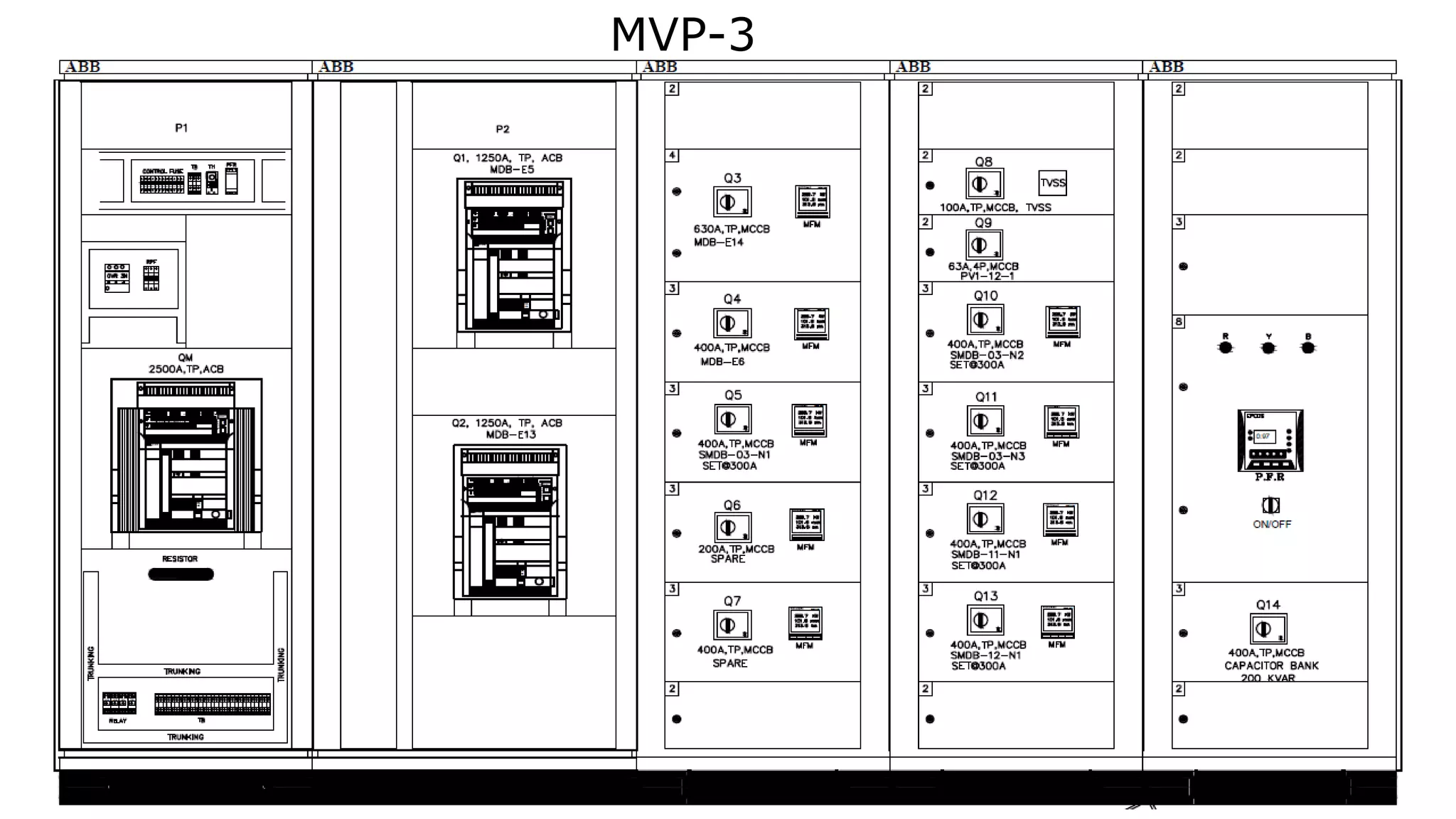
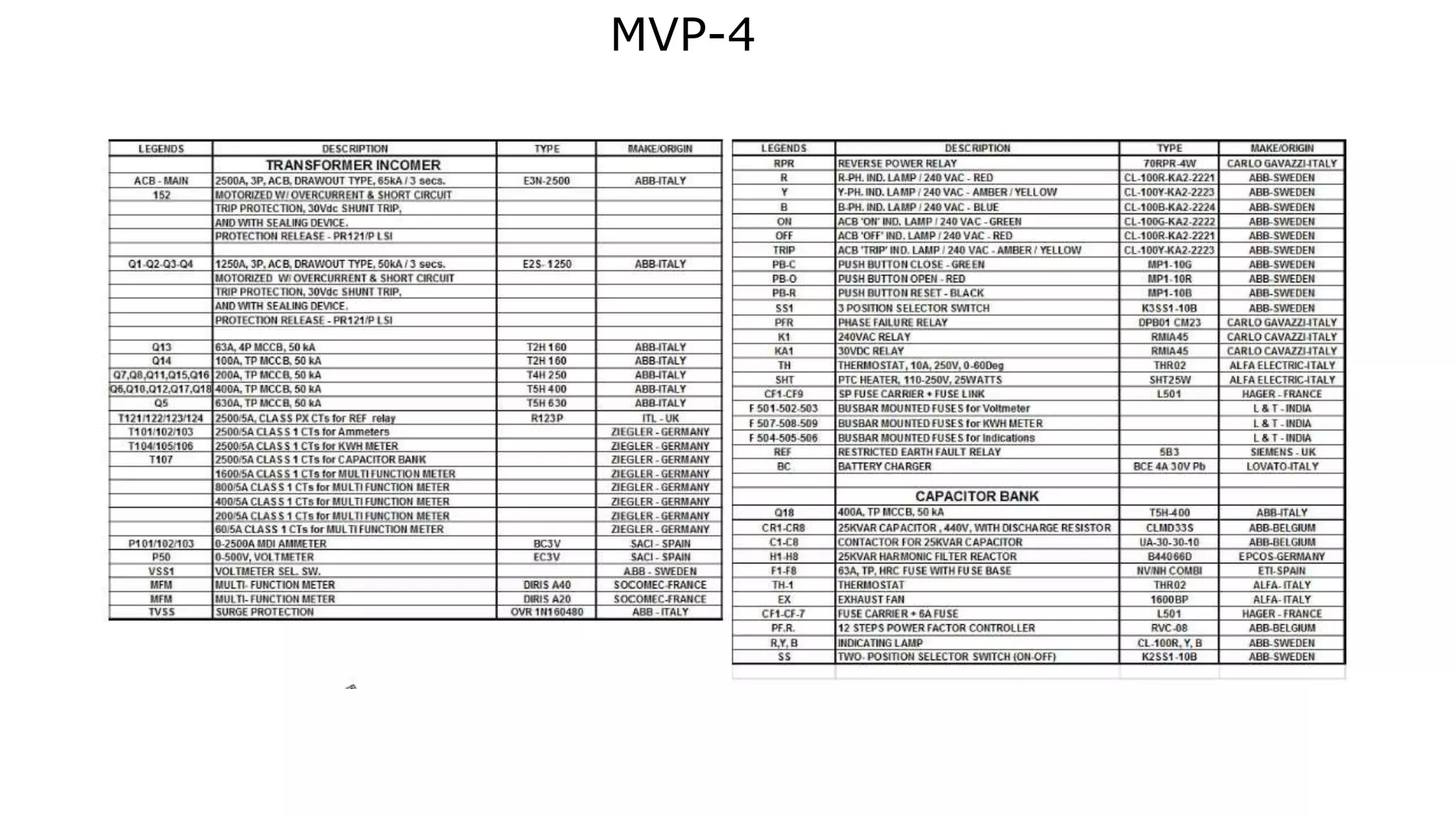
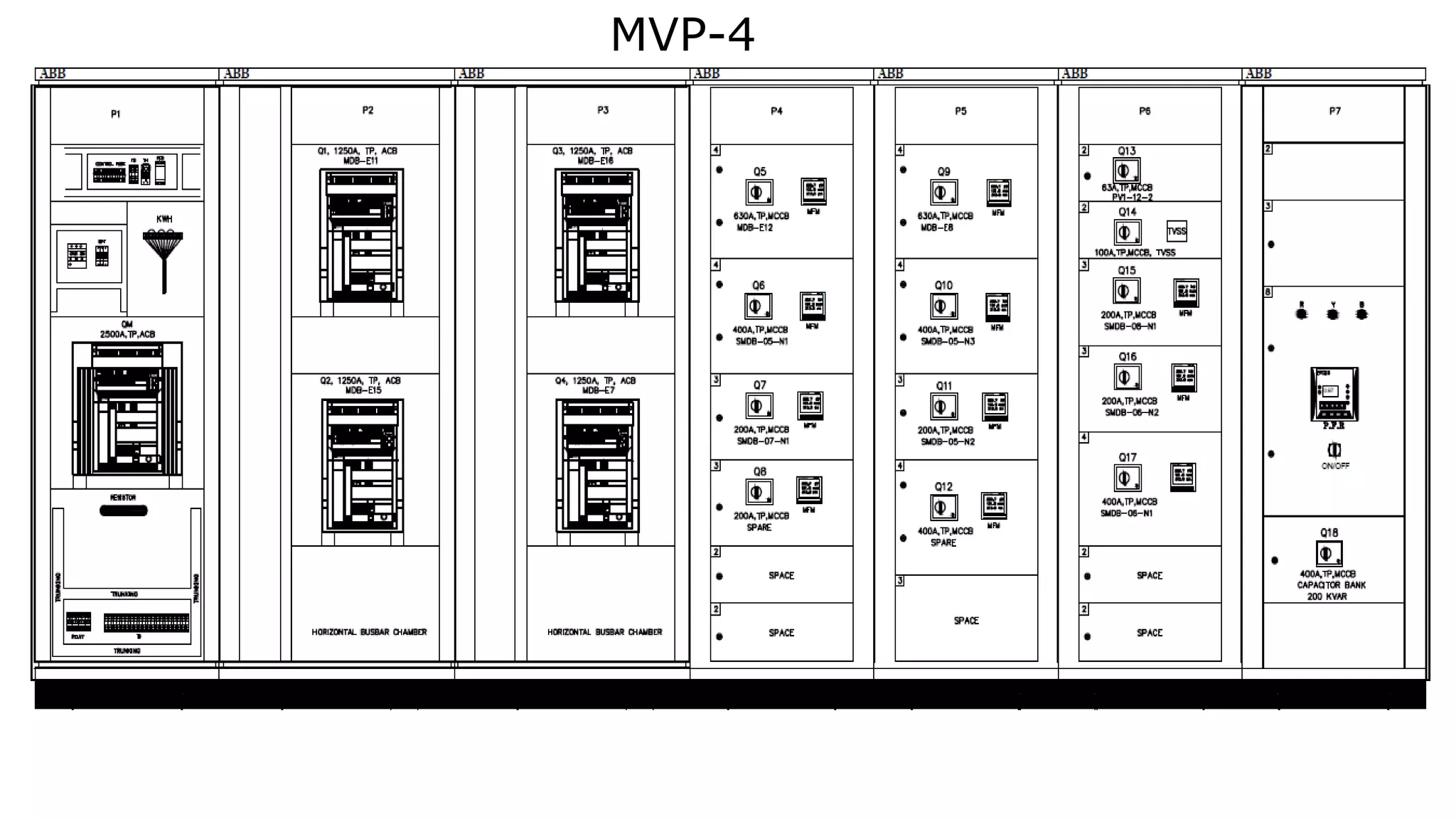
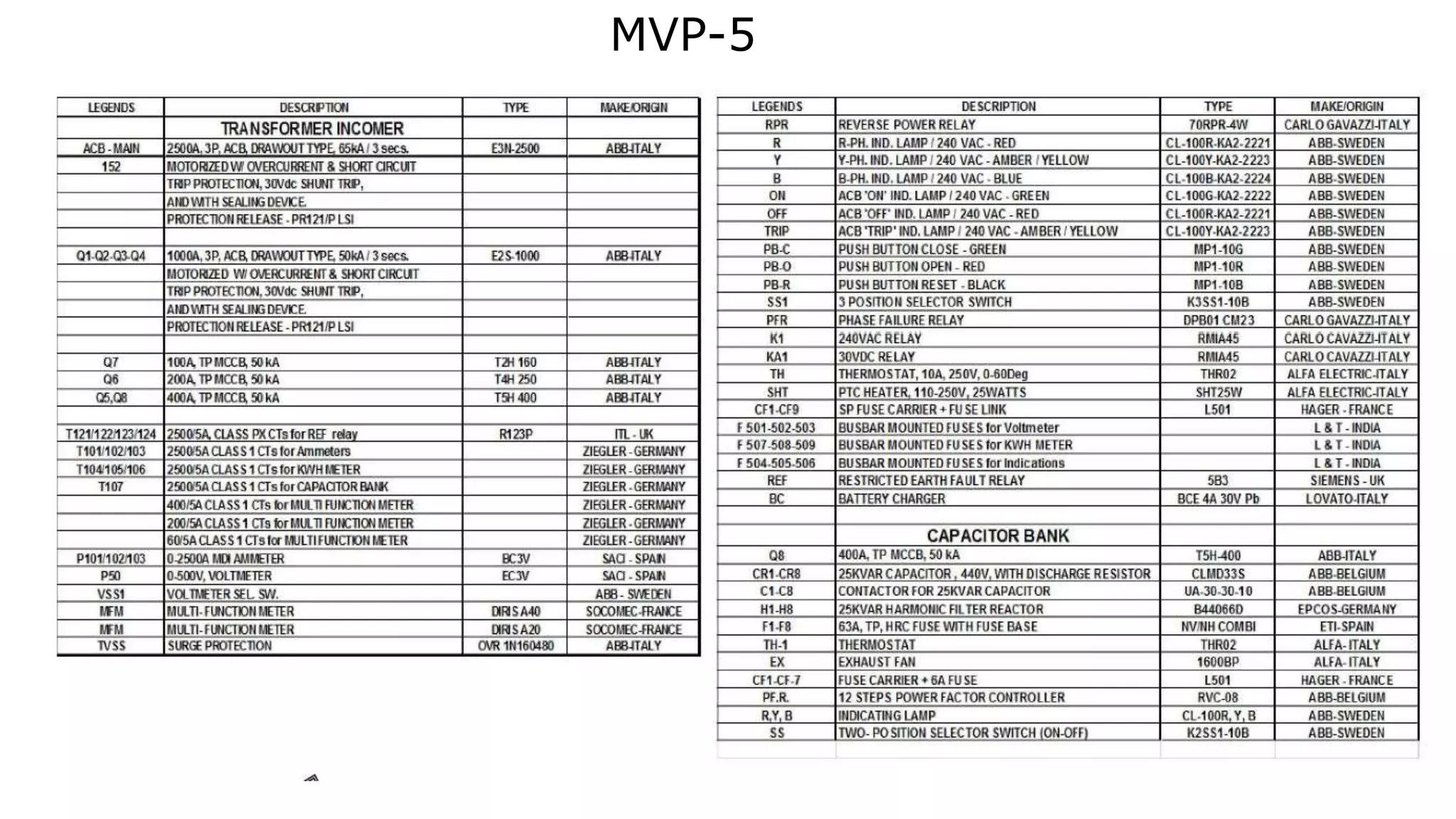
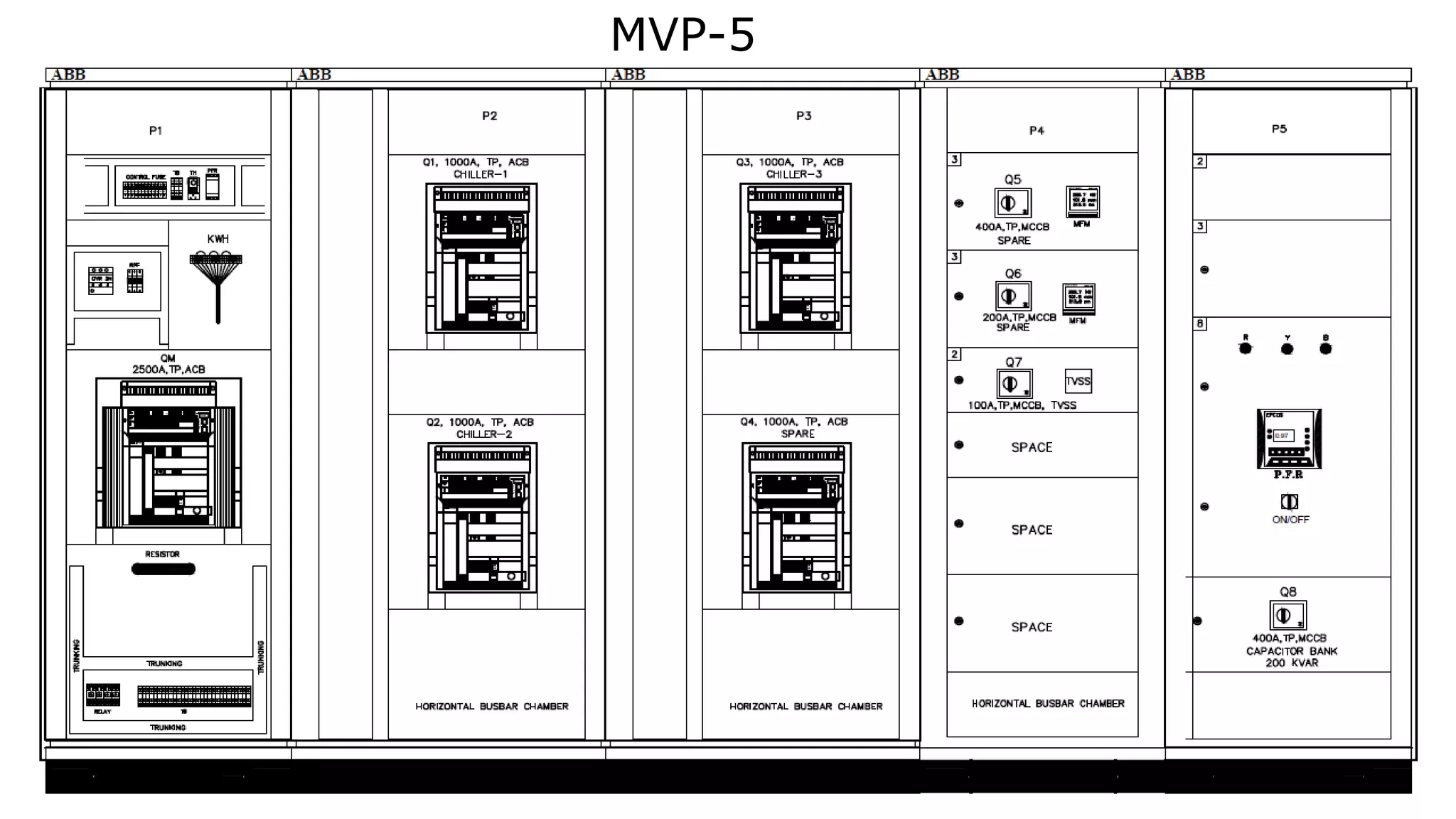
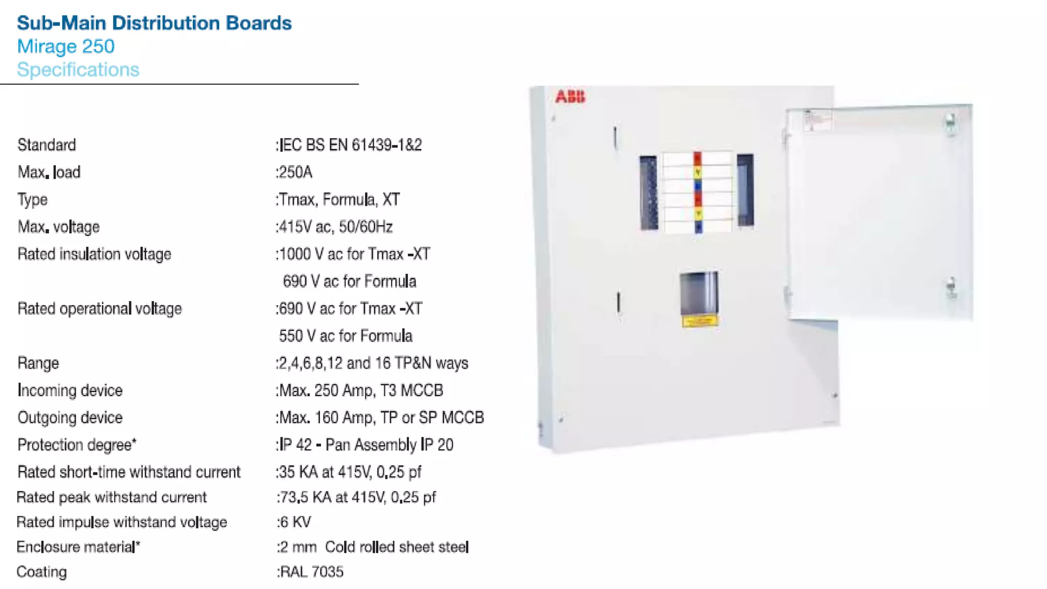
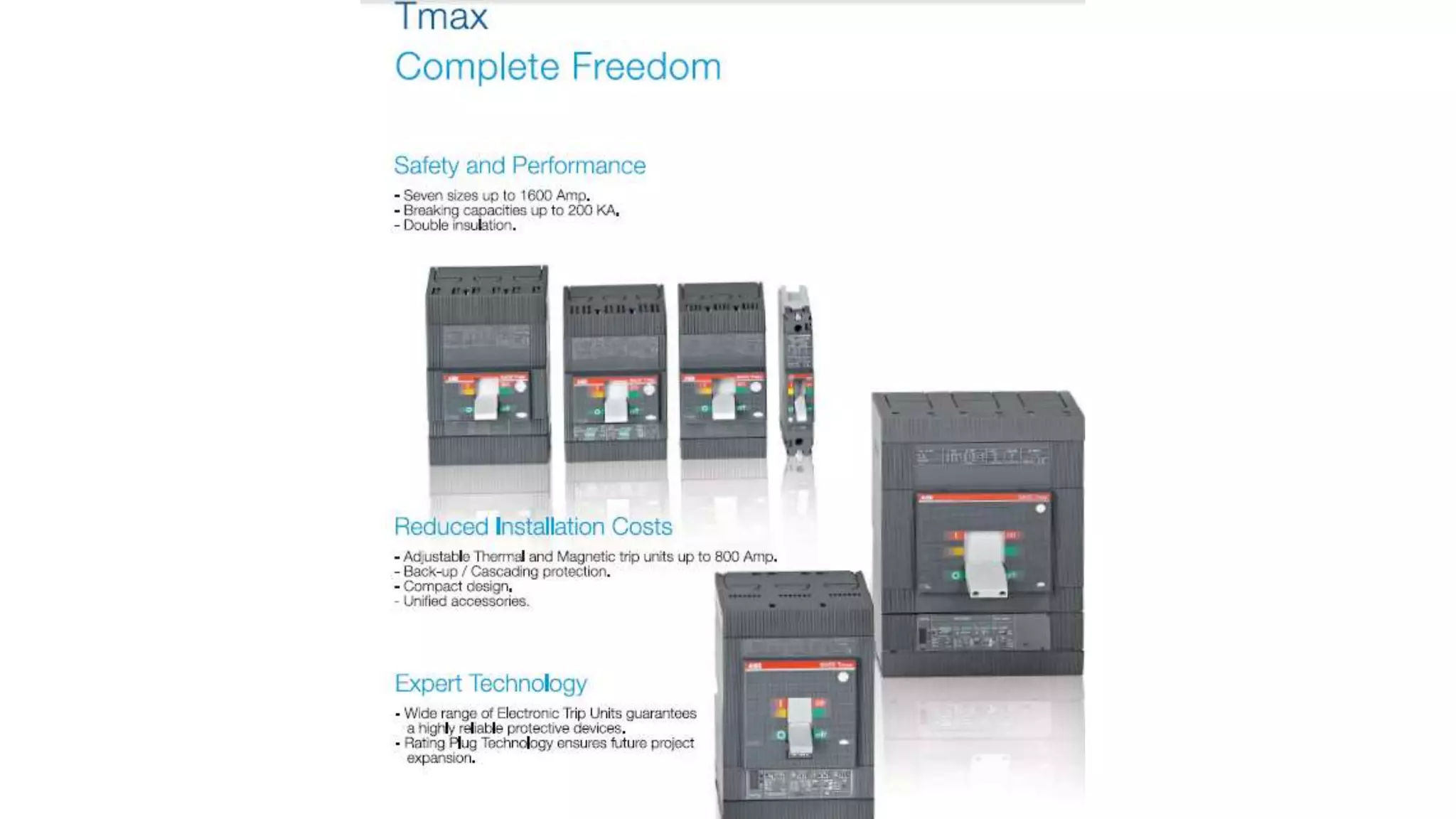
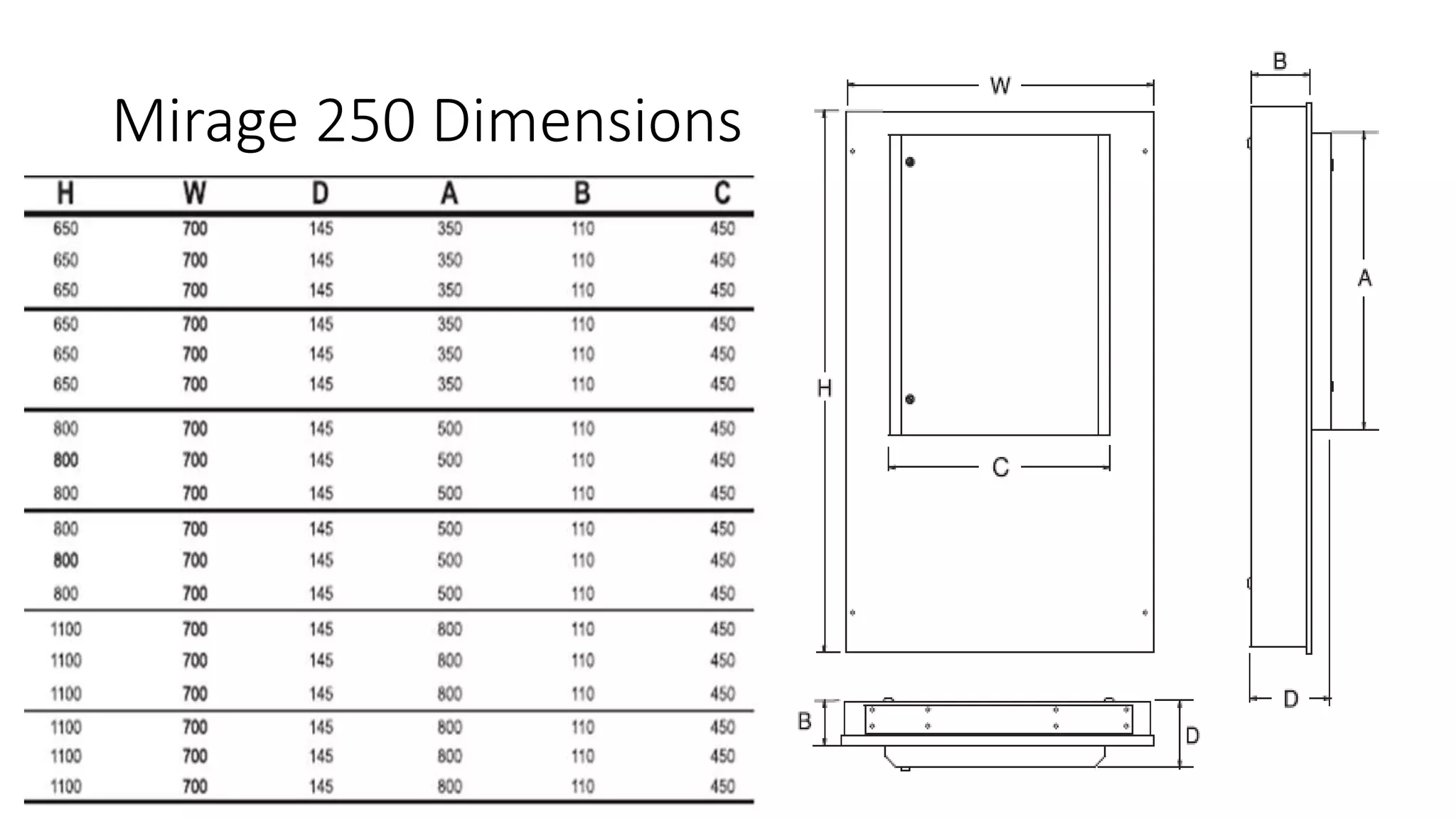
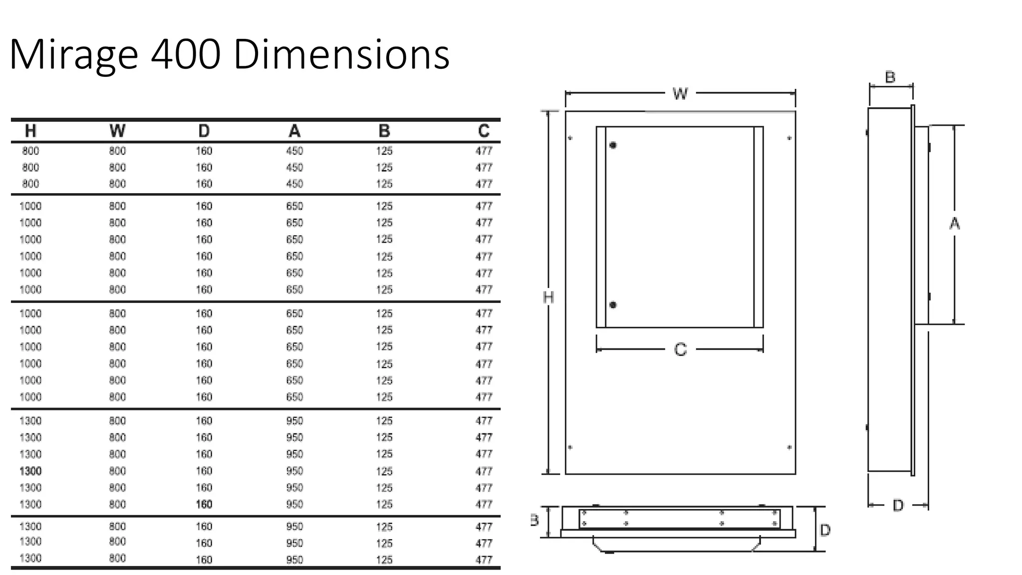
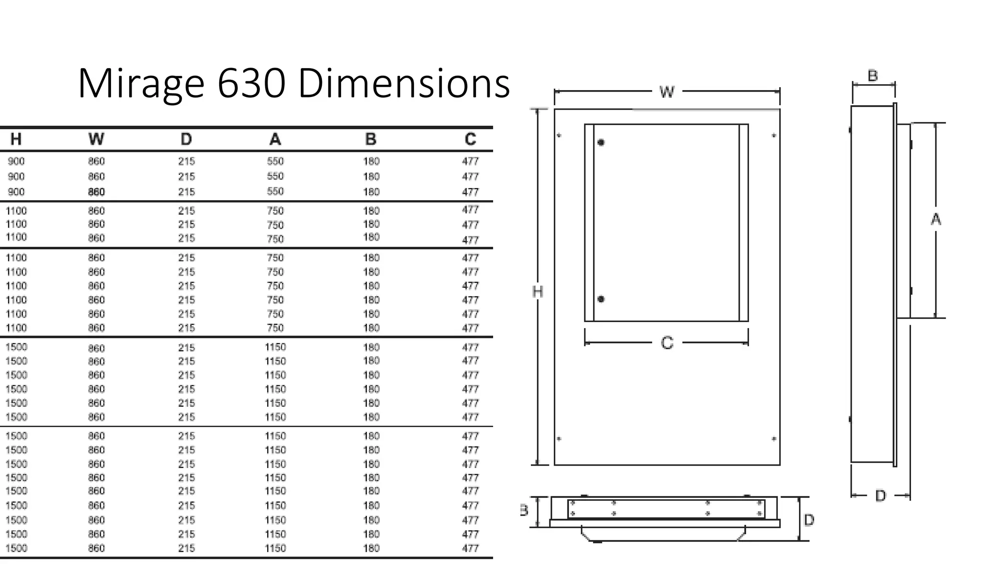
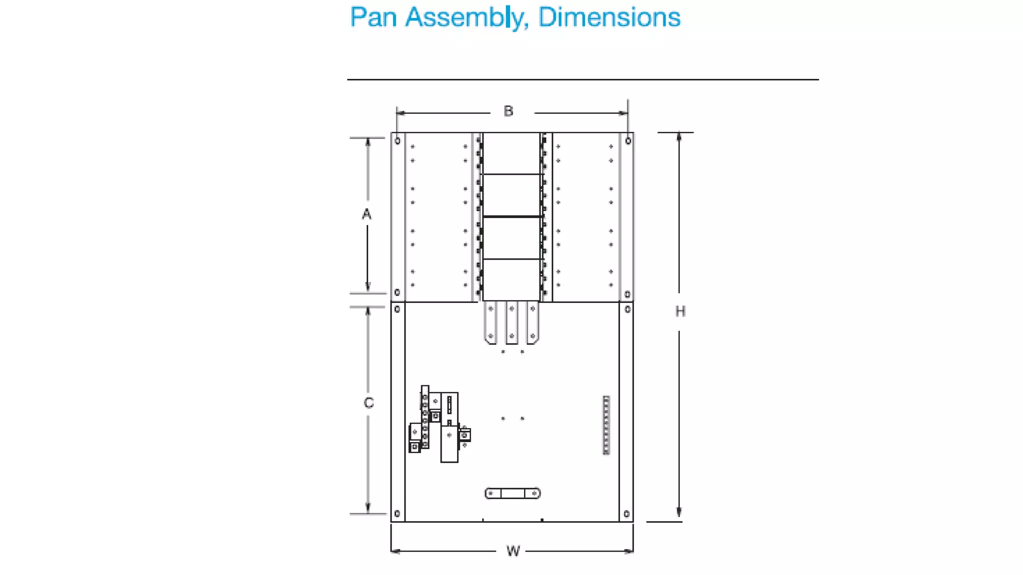
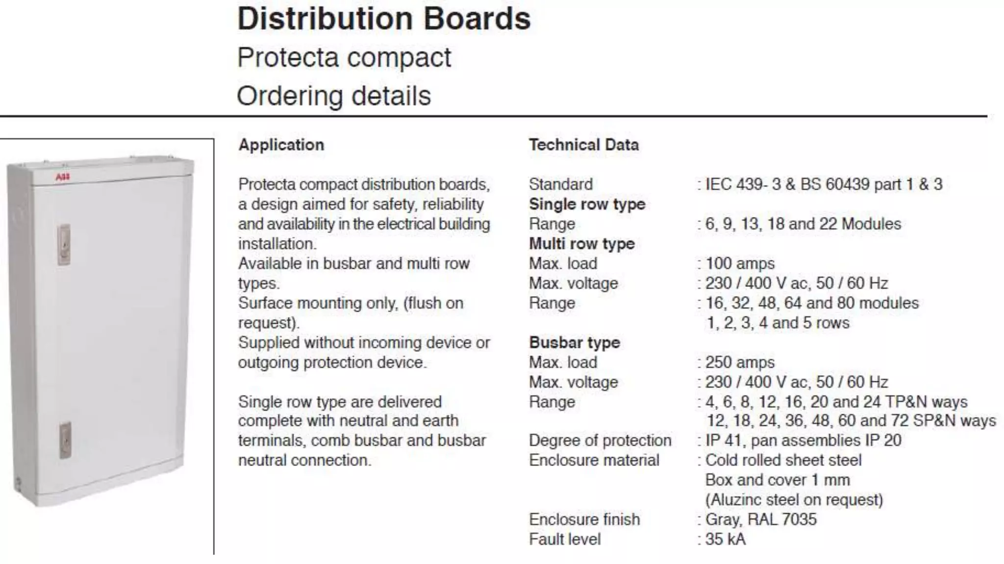
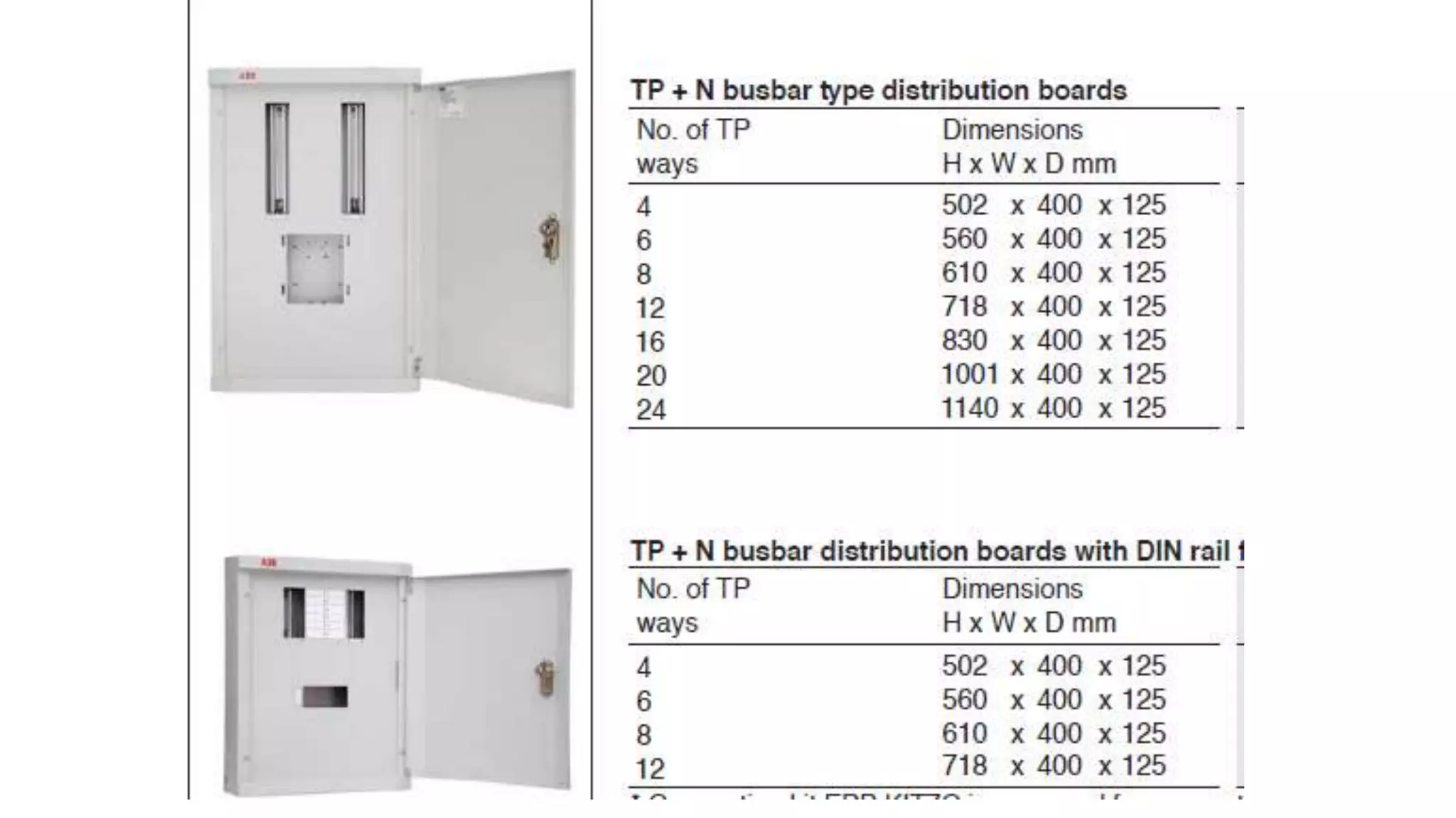
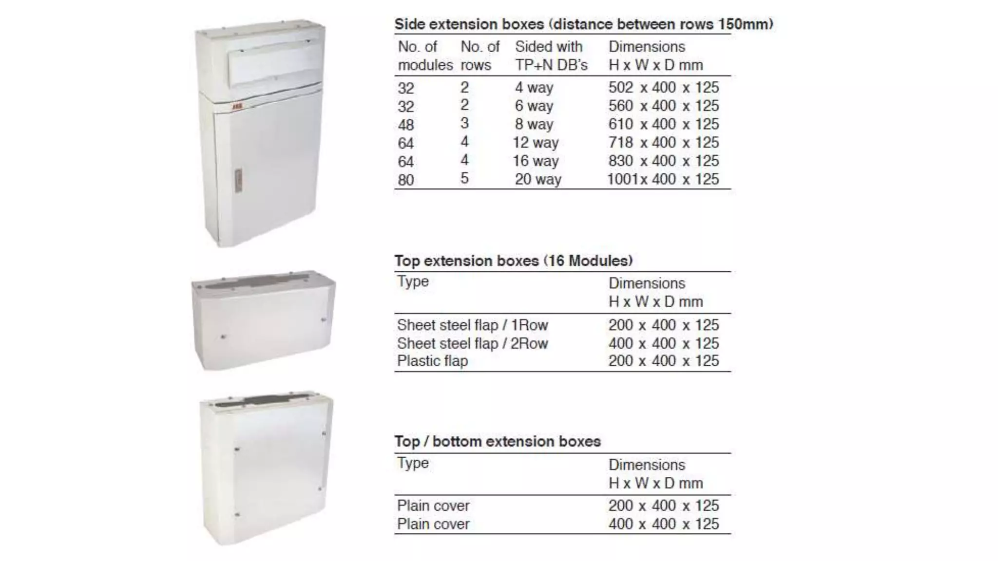
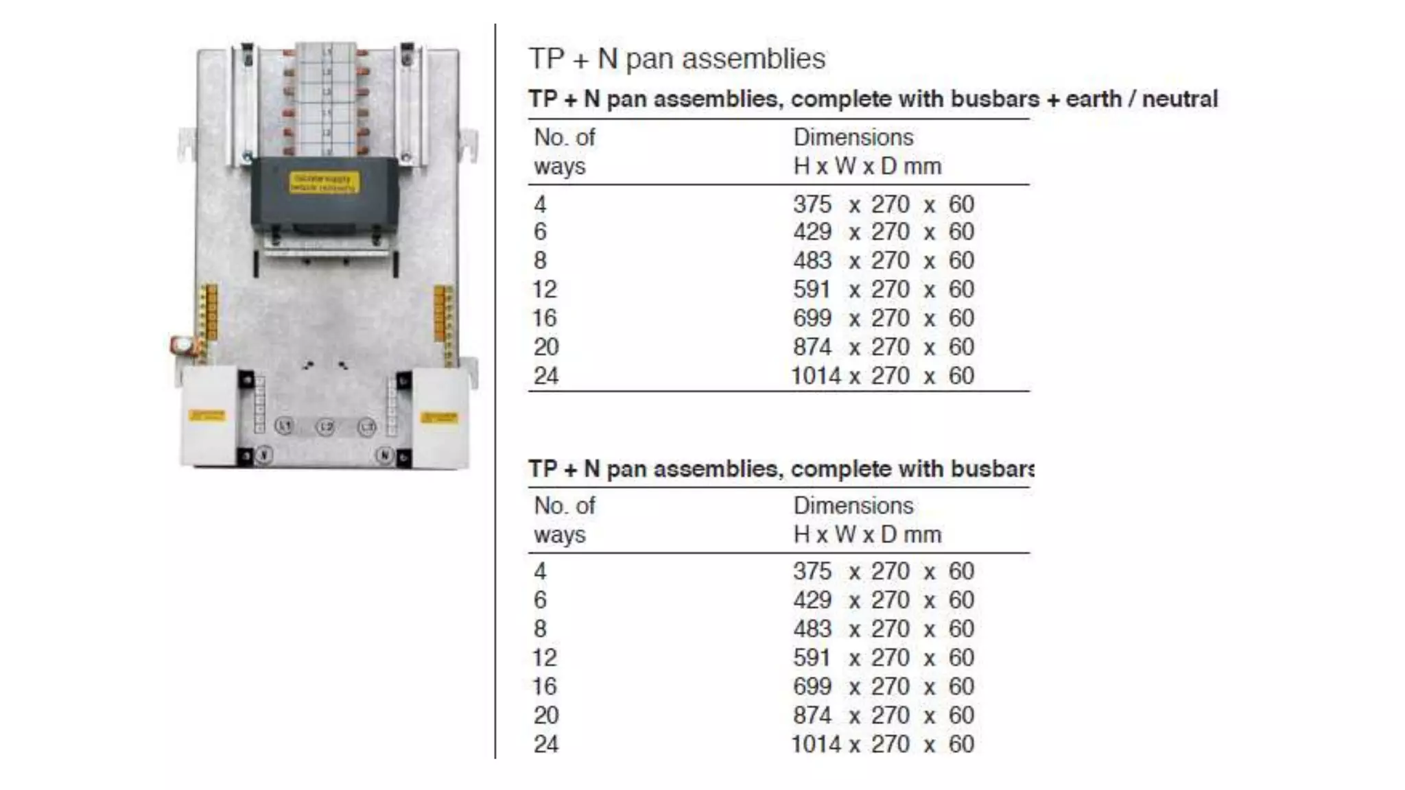
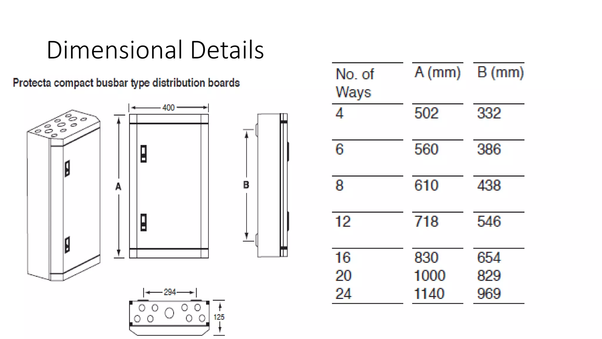
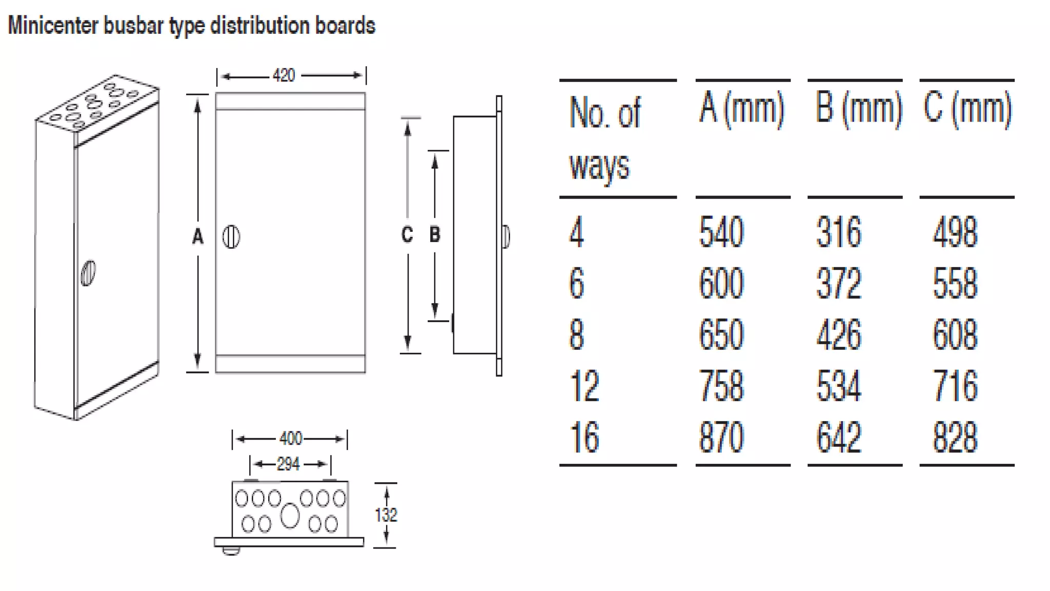
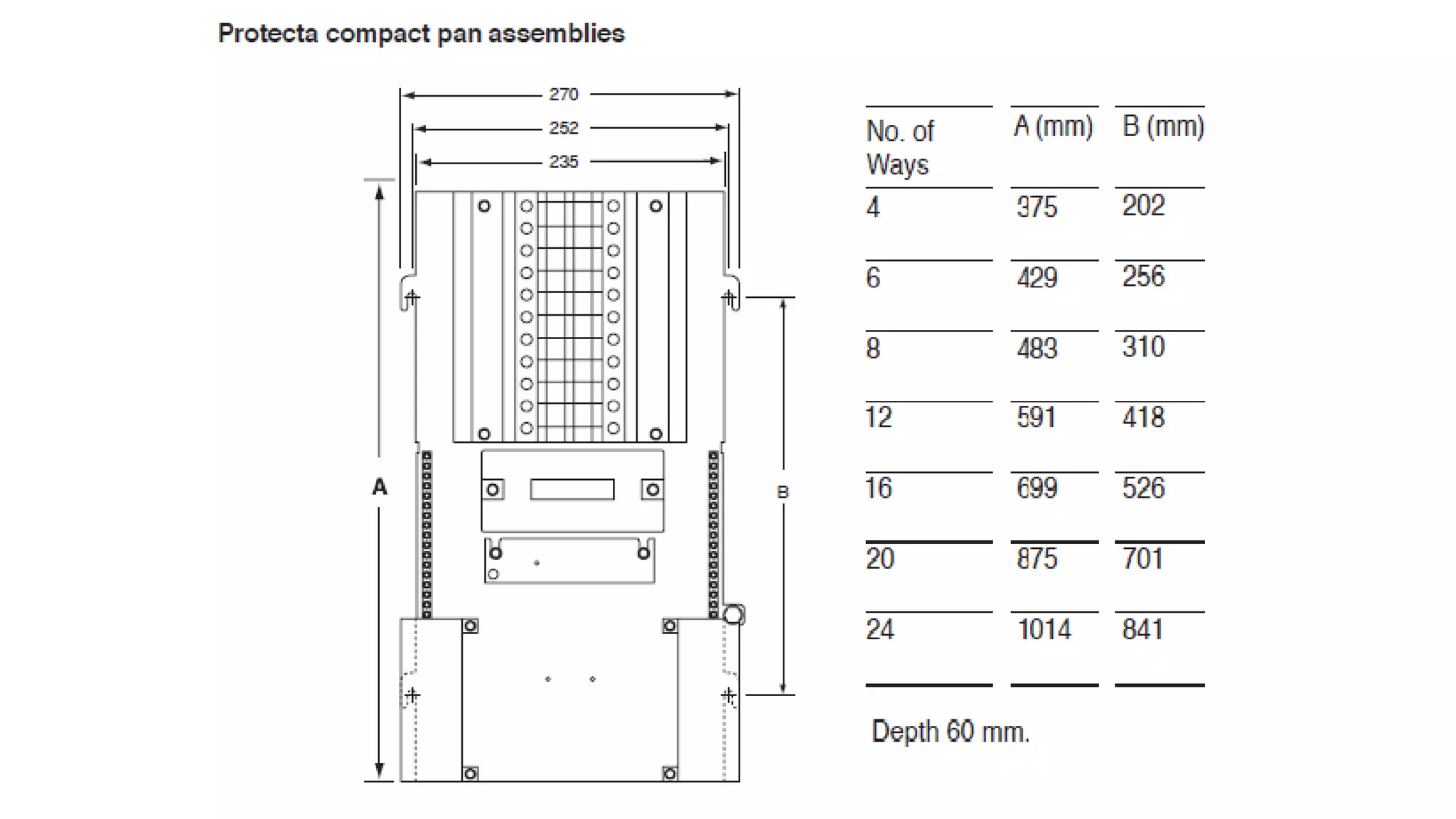
The document discusses medium voltage (MV) switchgear panels and sub-main distribution boards. It provides details on MV panel components, tests conducted, and protection against short circuits and direct/indirect contact. It also includes dimensional details and breaker information for Mirage sub-main distribution boards in 250A, 400A, and 630A sizes. Single-line diagrams and examples show potential layouts and component selection for MV panel construction.
This Presentation is about l.v switch gear design, presented during the graduation project final discussion 15/7/2018.
It presented a good summary of switch gear components and types and practicing on AL.HAMOOL W.T.P M.D.B design using SIEMENS SIVACON S8
Presentation made at the Nigerian Institution of Electrical & Electronics Engineers (NIEEE) Lagos Chapter. This article gives the reader the basic knowledge of what sub-stations are, how they are designed and the factors considered at the design stage as well as the various protections used at sub-stations.
This presentation described in a National Level Conference in CITM College Jaipur named as POWER SYSTEM PROTECTION TECHNIQUE: A REVIEW. This was presented by Sahid Raja Khan B.Tech. (Electrical Engineering) Hons.
I would like to share some knowledge of surge protection devices.
This presentation highlights some concepts of surge and surge protectors.
Presentation Index is as follows:
> Types of Surge
> Sources of Surge
> Surge Current & Voltage waveform
> Importance of Surge Protectors
> Types of Surge protectors
> Location of Surge Protectors
The major challenge in Indian power sector is operating upgrading of the transmission & distribution lines with efficient meteringApplication of smart grid devices for consistently condition monitoring of overhead lines &substation can decides the action of maintenance required and thus condition-based maintenance (CBM) technique can be implemented. To meet ever increase in demand, reduction of value of losses, utilization of huge renewable energy and absence of automation in power Transmission & Distribution, there is need of Preventive Maintenance (PM) & logy(RCM).
The financial growth of India also depends on availability of electricity. Indian power sector having characteristics as shortage of generation and high T & D losses up to 30% of total electricity generation with some parts of states of country up to 40%. When losses due to theft are added in the total then average losses increases up to 30%. The economical loss reaches at 1.5% of the national GDP which is increasing. To maintain stability of power system up gradation is essential. Transmission system is operated & regulated as per the Regulations & standards given by Central Electricity Regulatory Commission (CERC), Central Electricity Authority (CEA), State Electricity Regulatory Commissions (SERC). At present Maintenance technology is one of the topics of R & D for various countries.
Turnkey Solutions – the key to successful projects
----------------------------------------------------------------
EPC Solutions has all it takes to design, construct, and operate turnkey electrical substation solutions that efficiently support the reliable supply of electrical power on all voltage levels: decades of practical experience as a contractor and equipment manufacturer and a vast number of successfully completed projects all over the world, unparalleled expertise in all transmission processes, and proven excellence in project management. A distinguished tradition of innovation in power engineering, customized financing solutions, and outstanding quality standards in all production facilities worldwide round out the picture.
EPCS turnkey solutions for high-voltage substations incorporate the strong performance of one of the world’s leading engineering companies and one-stop supplier of power transmission products, solutions, and services. The scope of services comprises consulting, project management, system planning, engineering, commissioning, and comprehensive after-sales support. Centers of competence and branches all over the world create local value and ensure that EPCS experts are within close reach of every project.Customers worldwide benefit from numerous advantages of high-voltage substations from EPCS:
>One-stop approach comprising all technical, financial, and ecological aspects of the station’s entire life cycle
>Customized solutions based on proven EPCS technologies, even for the most challenging demands
>Freedom from coordination efforts and minimized financial and technical risk
Hazards in steel plant and their control, By B C dasBimal Chandra Das
Hazards and Accidents In the iron and Integrated steel industry- Recommendations to prevent and control exposure to ….. Safety Awareness, It is sharing of knowledge. By Bimal Chandra Das, Rtd. AGM (Safety), Bokaro Steel Plant,/ Bokaro. Kolkata
#Building wiring system#presentation#Wire is a single electrical conductor, w...Bint Shameem
#An “electrical power system” can be defined as a network of electrical components used to supply, transform, transfer and distribute electrical energy. An “electrical wiring system” instead, is responsible for powering specific elements within a system, that need electricity to work.
CIRCUIT BREAKER
A circuit breaker is an automatically-operated electrical switch designed to protect an electrical circuit from damage caused by overload or short circuit. Its basic function is to detect a fault condition and, by interrupting continuity, to immediately discontinue electrical flow. Unlike a fuse, which operates once and then has to be replaced, a circuit breaker can be reset (either manually or automatically) to resume normal operation. Circuit breakers are made in varying sizes, from small devices that protect an individual household appliance up to large switchgear designed to protect high voltage circuits feeding an entire city.
The Over and Under Voltage protection circuit can protect electrical appliance from in the condition of power surges.
The project theme was to design an economical and efficient power protection circuit that could be capable of safely isolating the power of machine incase of power surges in mains.
With more than 50 years of presence in the aerospace market, Crouzet Aerospace is a specialist providing customized solutions for electromechanical
switches, inductive sensors, electrical protection and cockpit equipment backed up by a loyal and experienced team of experts available worldwide.
http://www.crouzet-aerospace.com
Follow us on LinkedIn: https://www.linkedin.com/company/crouzet-aerospace
Crouzet Aerospace is a brand of InnoVista Sensors™.
InnoVista Sensors™ : your trusted partner of choice to face industrial challenges of today and tomorrow.
InnoVista Sensors™ is a worldwide industrial specialist of sensors, controllers and actuators for automated systems.
Through its brands, Crouzet Aerospace, Crouzet Automation, Crouzet Control, Crouzet Motors, Crouzet Switches and Systron Donner Inertial, InnoVista
Sensors™ offers a wide range of reliable, efficient and customizable components dedicated to the Aerospace & Defence, Transportation and Industrial
market and segments.
Thanks to the recognized expertise of its teams and a strong innovation policy, InnoVista Sensors™ brings performance enhancing solutions to its
customers worldwide.
www.innovistasensors.com
Contact us: http://www.crouzet-aerospace.com/contact-Crouzet-Aerospace/contact-us
15. MV Panels
The medium voltage switchgear panels metal enclosed,
indoor, with simple busbar, air insulated, are modular
assemblies of electric equipment, for AC, used in medium
voltage networks, which represents the optimal solution in
primary and secondary power distribution.
This type of medium voltage switchgear is broadly used
in the energy sector, both on the power generation and
distribution side, connection points and power points
as well as on the secondary distribution for the MV / LV
medium voltage transformer stations, and industrial or
large individual consumers’ networks
16. Tests Conducted on Supplied MV Panels
• Type tests
• The Standard foresees the following
type tests:
• • overtemperature limits
• • withstanding the applied voltage
• • short-circuit withstand current
• • efficiency of the protection circuit
• • insulation distances
• • degree of protection
• • mechanical operation
Individual tests
The Standard foresees the following
individual tests:
• Visual inspection of the switchgear,
including checking the cabling, and,
if necessary, an electrical operation
test
• A dielectric test
• Checking the means of protection
and
the electrical efficiency of the
protection circuit
17.
18.
19. ArTu K-The structure is made entirely of hot galvanised steel sheet, which
guarantees the equipotential of the switchgear.
20. Forms of Segregation
By form of segregation, the type of division foreseen inside the switchgear is intended. Segregation
by means of barriers or partitions (metal or insulating) can have the purpose of:
- ensuring protection against direct contacts (at least IPXXB), in the case of access to
a part of the switchgear cut off from the power supply, in relation to the rest of the
switchgear which remains supplied with power
- reducing the probability of striking and propagation of an internal arc
- preventing passage of solid bodies between different parts of the switchgear (at least
IP2X degree of protection).
By partition, the separating element between two compartments is intended, whereas the barrier
protects the operator from direct contacts and from the effects of the breaking apparatus arc
in the normal direction of access.
The following table given in the IEC 60439-1 Standard highlights the typical forms of segregation
which can be obtained by using barriers or partitions:
24. Example
Existing plant data:
Vn=400 V
fn=50Hz
Icc=35kA
Let us suppose that in an existing plant there is electric switchgear with an Icw of 35kA and
that, in the installation point of the switchgear, the prospective short-circuit current is 35kA.
Now let us imagine that it is decided to extend the power of the plant and that the short-circuit
value increases to 60 kA.
Plant data after extension:
Vn=400 V
Fn=50Hz
Icc=60kA
Since the switchgear Icw is lower than the short-circuit current of the plant, to check that the
existing switchgear is still compatible, you must:
- determine the values of I2 t and of Ip let through by the circuit-breaker placed on the
supply side of the switchgear
- check that the protection devices located inside the switchgear have adequate breaking
capacity, individually or for back-up.
Icw = 35kA from which:
I2 t switchgear = 352 x1 =1225 MA2s
Ipswitchgear = 73.5 kA
25. Let us suppose that, on the supply side of the switchgear, a Tmax T5H moulded-case circuit-breaker
(Icu=70kA@415V) is installed
I2 tinterruttore< 4MA2 s
Ipinterruttore<40kA
since
I2 tcircuit-breaker > I 2 tswitchgear
Ipcircuit-breaker > Ipswitchgear
The switchgear (structure and busbar system) turns out to be suitable.
With regard to the circuit-breakers located inside the switchgear, let us suppose that these
are Tmax T1,T2,T3 moulded-case circuit-breakers, version N with Icu=36kA@415V. From the
Back-up tables it can be seen that the circuit-breakers present in the switchgear are suitable
for the plant as their breaking capacity is increased to 65 kA by the T5H circuit-breaker placed
on the supply side.
27. Protection against the direct contacts
• - Protection by means of insulation of the live parts
The live parts must be completely covered with insulation which can only be
removed by destroying it. This insulation must be made of suitable materials
able to resist the mechanical, electrical and thermal stresses they may be
subjected to during service over time. Paints, varnishes, lacquers and other
similar products used alone are not generally considered suitable for
providing adequate insulation for protection against direct contacts.
• - Protection by means of barriers or housings
All the external surfaces must have a degree of protection of at least IP2X or
IPXXB.
The distance between the mechanical devices provided for protection and
the live parts protected by them, must not be less than the values specified
for the surface and air distances. All the barriers and housings must be
securely fixed in place. Bearing in mind their type, size and arrangement,
they must be sturdy and long-lasting enough to resist the forces and stresses
which can develop during normal service, without reducing the air insulation
distances.
28. Protection against the indirect contacts
• - Protection made using protection circuits
• The protection circuit can be made separate from the metal housing, or the same
housing can be used as part of the protection circuit. The exposed conductive
parts of the switchgear which do not constitute a danger, since they cannot be
touched on large surfaces or taken hold of by hand because they are small (for
example, screws, nameplates, etc.), do not require connection to the protection
circuit. The manual operating parts, such as levers, handles and other devices
made of metal, must, on the other hand, be connected securely to the parts
connected to the protection circuit or must have additional insulation suitable for
the maximum insulation voltage of the switchgear. The metal parts coated with a
layer of paint or enamel cannot normally be considered suitably insulated to
satisfy these prescriptions.
• For covers, doors, closure plates, etc., the normal connections made using metal
screws or hinges are sufficient for electrical continuity, as long as electrical
apparatus which requires a connection of the exposed conductive parts to earth
is not mounted on them. In this case, the exposed conductive parts must be
connected by means of a protection conductor with a cross-section at least the
same as the maximum cross-section of the phase conductor supplying the
apparatus.
38. Practical indications for constructing the
switchgear
• Positioning the circuit-breakers
With regard to positioning the circuit-breakers inside the switchgear,
there are some indications which are in contrast with each other. This is
because requirements of thermal type often contrast with the needs of
another kind. It is therefore the panel builder who, knowing the plant
details, its installation location and its actual use better, can design the
front of the switchgear in an optimal way.
• A good rule is to try to position the circuit-breakers so as to reduce
the higher current paths as far as possible, thereby reducing the power
dissipated inside the switchgear with undoubted benefits from the
thermal and economic points of view.
39.
40. In the case of switchgear with a lot of columns, where possible it is advisable to position the main circuit
breaker in the central column.
This way the current is immediately divided into the two branches of the switchgear and the cross-section of
the main distribution busbars can be reduced.
41.
42.
43. Anchoring the conductors near the circuit-breakers
It is necessary for the cables and busbars to be fixed to the structure inside the switchgear. In fact, during a short-
circuit, the dynamic stresses produced in the conductors could damage the terminals of the circuit-breakers.
47. Example of construction of ArTuK switchgear
Selection of the circuit-breakers and ducts outside the switchgear
Circuit-breakers
As shown on the single-line diagram, the circuit-breakers selected are:
1 Emax E3N3200 PR111-LSI In 3200 (main switchgear circuit-breaker)
3 Emax E1N1250 PR111-LSI In 1250 (circuit-breakers for the three outgoing feeders)
Ducts
Incoming, from the transformer there is the following:
1 Bus duct with Iz = 3150 A; L = 5 m
Outgoing from the switchgear, hypothesising overhead laying on perforated trays, there is:
1 cable with L = 20m 3x(3x120) Iz = 876,3 A
1 cable with L = 70m 3x(3x120) Iz = 876,3 A
1 cable with L = 100m 3x(3x120) Iz = 876,3 A
48. Front of switchgear, distribution system and metal
structure
• A possible layout
for the busbars
and circuit-
breakers is given
in the following
figure