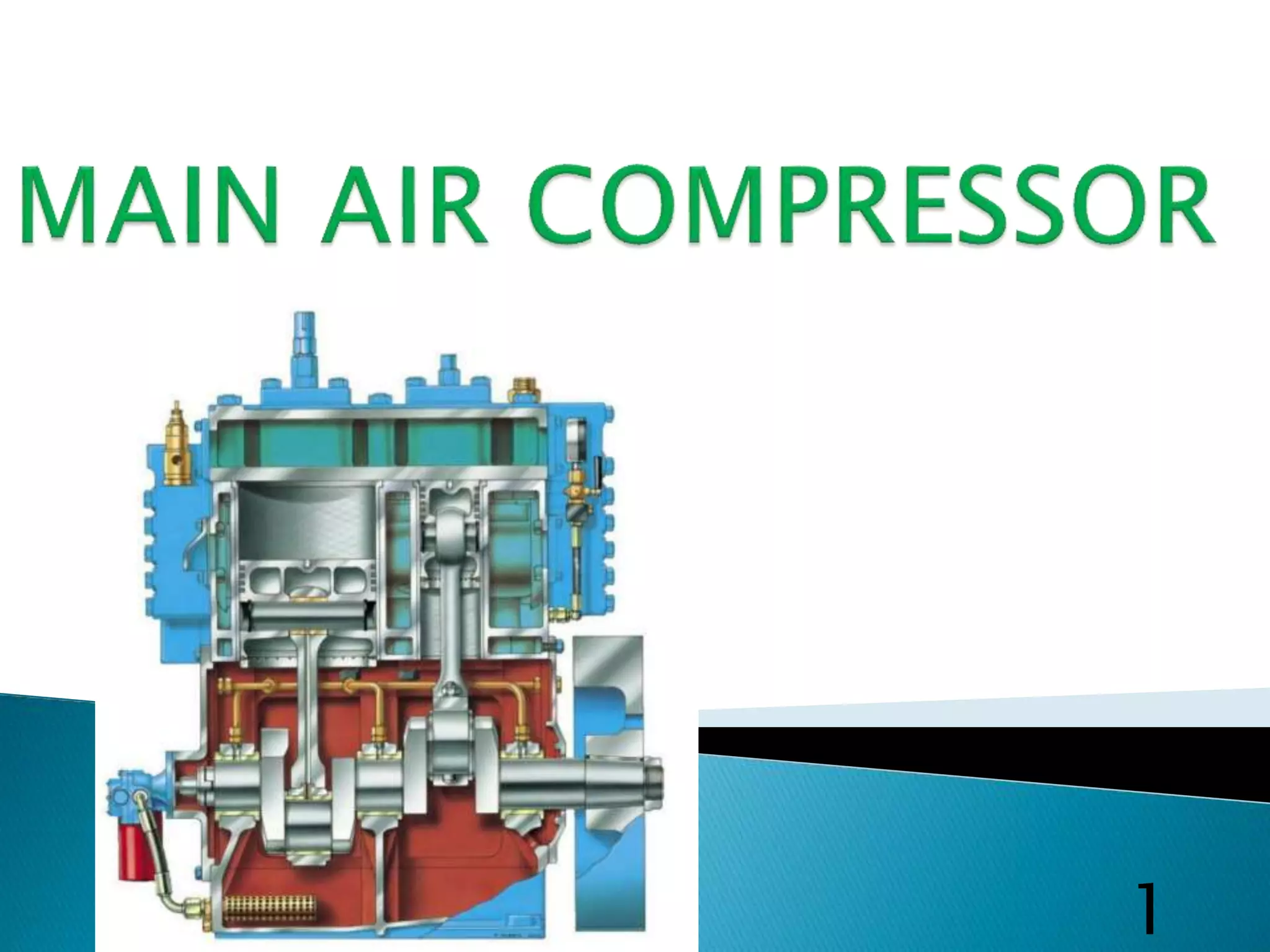
1
 Marine air compressor is important auxiliary machinery
on ships It is used for producing compressed air, which
has a number of applications on board, both in the
engine and deck department.
Uses of compressed air on ship
 30 bar for starting of main engine and auxiliary engine.
 7 bar for automation and control air for main and
auxiliary engine.
 For chipping, buffing, pressurized water jet cleaning,
pneumatic tools, pneumatic pumps like Weldon pumps.
 Ships whistle and fog horn.
 For supplying water through hydrophore.
 For soot blowing of boiler and economizer.
 For general cleaning and services 2
 Two starting compressor must be fitted ,of
sufficient total capacity to meet the engine
requirements.
 Each compressor must be able to press up air
receiver from 15 bar to 25 bar in 30 minutes.
 If the emergency generator is arranged for
pneumatic starting, the air supply shall be from a
separate air receiver.
 Total air receiver capacity must be sufficient for 12
starts for reversible engine and 6 starts or non-
reversible engines.
3

4
 Air is drawn through the air inlet filter and suction valve
into the first stage cylinder on each downwards stroke of
the piston.
 As the piston commences it’s upwards stroke, the spring
plates close the suction valve and the air is compressed in
the cylinder until the required pressure is reached.
 At this pressure, the first stage delivery valve opens and the
compressed air is delivered to the first stage cooler.
 It passes through the cooler to the outlet cover and then
into the second stage cylinder through the second stage
suction valve.
 After compression, the air passes through the delivery valve
into the after cooler to the receiver.
5
Volumetric efficiency
 It is the ratio of the volume of air taken in during each stroke to the swept volume
of the cylinder.
 A loss in the volumetric efficiency of the compressor can be due to the poor valve
condition, dirty intake filter , increased bumping clearance , discharge line
blocked ,or restrictions in the intercooler
intercooler between stages.
6
6
 1-The work done in compressing the air is
reduced, thus power can be saved.
 2-Prevents mechanical problems as the air
temperature is controlled.
 3-The suction and delivery valves remain in
cleaner condition as the temperature and
vaporization of lubricating oil is less .
 4-The machine is smaller and better balanced.
 5-Effects from moisture can be handled better,
by draining at each stage .
7
 Reduced air temperature, volume and increased air density for next
stage
 So increased volumetric efficiency and compressor efficiency.
 Due to reduced temperature give better lubrication for cylinder and
piston rings
 Drain are fitted from which water and excessive oil can be drained out,
to prevent air bottle corrosion and starting air explosion and fouling of
inter coolers and pipe.
 Save the work done.
Advantages of inter cooling of air compressor
 To avoid excessive temperature rise associated with higher compression
ratios, and to approach isothermal compression.
 Saving in power.
 Volumetric efficiency is increased.
 Reduced the volume of air delivered and also reduced the compressor
size.
 It can reduce the air temperature.
 Due to less temperature suction & delivery valves remain cleaner without
being fouled with carbonized oil.
 It can avoid a danger of an explosion takes place in compressor cylinder.
 It allows good lubrication of the compressor piston.
 Moisture separation is easier through inter cooler drains.
8
 To reduce final discharge air temperature thus air bottle size can be
reduced.
 To reduce air volume after it has been compressed to the final
pressure.
 So greater amount of air could be stored in air bottle.
 Increase volumetric efficiency
Type of intercooler and after cooler
 Intercooler is single pass type
 After cooler is double pass U-tube type
Normal parameters of air compressor
 LP discharge pressure: 4 bars
 HP discharge pressure: 30 bars.
 Intercooler inlet air temperature: 130 ° C
 Intercooler outlet air temperature: 35 ° C
 After cooler inlet air temperature: 130 ° C
 After cooler outlet air temperature: 35 ° C
9
 Change the switch to manual position on the switch
board.
 Check the L.O sump level and condition.
 Open the moisture drain valve.
 Open the compressor discharge valve & charging valve
of air bottle.
 Open cooling water system valves.
 Turn the compressor flywheel by hand (one turn).
 Start the motor, after draining the moisture shut the
drain valve.
 Check the motor ampere consumed.
 Check the pressure gauge readings.
 Frequently drain the moisture.
 When charging full, open drain valve and stop the
compressor
10
 It is the clearance given to avoid the chance of mechanical
bumping of the piston and the cylinder head cover.
 It is the distance between the top of the piston and the
cylinder cover when the piston is at Tdc.
 It is approximately between the 0.5 % to 1% of the cylinder
bore.
 It is checked by placing lead metal ball on the top of the
piston and then turning the compressor manually and then
take it out and measurment is done by vernier.
 It can be adjusted by placing the gasket between the cylinder
block and cylinder head cover .we can also adjust it by adding
the shims under the connecting road.
11
11
 Checked by filling time with the previous record and also check
the first stage discharge pressure.
 If compressor efficiency is lower, compressor will run longer and
compressor temperature will rise.
 First stage and second stage pressure gauge must be correct and
stable.
 No escape of air from suction filter.
 Intercooler and after cooler outlet air temperature should not be
high.
 If open drain valve nothing can be found.
 Low L.O consumption.
 Oily air mixture must not blow out from breather pipe 12
 Relief valve
- Normally fitted at discharge side of 1st stage
intercooler and 2nd stage after cooler.
- Each valve operate at 10% above stage working
Pressure.
 Bursting disc
It is fitted on each cooler shell of air compressor,
relief of pressure when cooler tubes burst.
13
 Fusible plug on the discharge side of the
compressor (above 105˚)
 Lube oil low pressure alarm and trip.
 Water high temperature alarm and trip.
 Water no-flow trip.
 Motor overload trip.
 Delivery air temperature high max 93˚C
 Drain valve at each coolers / unloader.
 Non return valve at delivery side.
14
 All the compressors need to be unloaded during starting ,stopping and
the regular intervals.
why unloading at starting
 During the starting of a motor the starting current is very high , so to
avoid further overloading of the motor the compressor is started
unloaded
why at regular intervals
 Intermittently the compressor is unloaded to remove the condensed
water inside which could go outside with the air
why at stopping
 At stopping the same is done so as to drain all the moisture inside an in
preparation fort next starting.
Unloader (Magnetic valve)
Normally, an electrical timer relay mechanism is applied for no load
start of the compressor, when the compressor starts ,the timer function
to open the unloader (magnetic valve) to enter no load state (unloading)
approximate 5-10 seconds ,the magnetic valve closed and pressure rise
operation starts.
15
16
 First of all make sure all the spare including
critical spares are available onboard before
commencing the work.
 Be sure to disconnect both main power supply
and operating power supply during
maintenance.
 Putting up sign boards
 Before maintenance discharge the compressed
air from their receiver tank and make sure no
pressure is left in the compressor.
 Crankcase oil and jacket water is drained
completely.
 Opened up the cylinder head bolts and take
out the first stage valve assembly.
17
 Remove the bottom end bolts and take out the
piston, remove the circlip to take out the gudgeon
pin out .
 Remove the top end bearing and piston rings from
the piston.
 All the part like piston rings ,piston outer diameter
, groove width should be calibrated .
 Cylinder liner should be calibrated with bore gauge
 Crankpin diameter should be measure with
micrometer at two places forward aft and port
starboard .
 Sump oil should be renewed.
 Suction and discharge valve should be lapped for
proper sealing. 18
 Piston rings must be renewed if necessary.
 Renew lube oil filter and suction filter.
 Checking the bumping clearance by putting the lead ball
on the top of the piston.
 Refill crankcase with new lube oil .
 Turn the compressor by putting the bar in the flywheel to
check the free movement of the reciprocating parts.
 After open the water to detect any leakages .
 Manually open the drain valve to run the compressor
initially for just few second ,check the motor amperes.
 Keep close eye on pressure gauge that how much time is
taken to press up the bottle till 25 bar.
 All records of clearances must be kept with in and send
to the company.
19
20
21
YOU
22

Main air compressors PPT.pptx

  • 1.
  • 2.
     Marine aircompressor is important auxiliary machinery on ships It is used for producing compressed air, which has a number of applications on board, both in the engine and deck department. Uses of compressed air on ship  30 bar for starting of main engine and auxiliary engine.  7 bar for automation and control air for main and auxiliary engine.  For chipping, buffing, pressurized water jet cleaning, pneumatic tools, pneumatic pumps like Weldon pumps.  Ships whistle and fog horn.  For supplying water through hydrophore.  For soot blowing of boiler and economizer.  For general cleaning and services 2
  • 3.
     Two startingcompressor must be fitted ,of sufficient total capacity to meet the engine requirements.  Each compressor must be able to press up air receiver from 15 bar to 25 bar in 30 minutes.  If the emergency generator is arranged for pneumatic starting, the air supply shall be from a separate air receiver.  Total air receiver capacity must be sufficient for 12 starts for reversible engine and 6 starts or non- reversible engines. 3
  • 4.
  • 5.
     Air isdrawn through the air inlet filter and suction valve into the first stage cylinder on each downwards stroke of the piston.  As the piston commences it’s upwards stroke, the spring plates close the suction valve and the air is compressed in the cylinder until the required pressure is reached.  At this pressure, the first stage delivery valve opens and the compressed air is delivered to the first stage cooler.  It passes through the cooler to the outlet cover and then into the second stage cylinder through the second stage suction valve.  After compression, the air passes through the delivery valve into the after cooler to the receiver. 5
  • 6.
    Volumetric efficiency  Itis the ratio of the volume of air taken in during each stroke to the swept volume of the cylinder.  A loss in the volumetric efficiency of the compressor can be due to the poor valve condition, dirty intake filter , increased bumping clearance , discharge line blocked ,or restrictions in the intercooler intercooler between stages. 6 6
  • 7.
     1-The workdone in compressing the air is reduced, thus power can be saved.  2-Prevents mechanical problems as the air temperature is controlled.  3-The suction and delivery valves remain in cleaner condition as the temperature and vaporization of lubricating oil is less .  4-The machine is smaller and better balanced.  5-Effects from moisture can be handled better, by draining at each stage . 7
  • 8.
     Reduced airtemperature, volume and increased air density for next stage  So increased volumetric efficiency and compressor efficiency.  Due to reduced temperature give better lubrication for cylinder and piston rings  Drain are fitted from which water and excessive oil can be drained out, to prevent air bottle corrosion and starting air explosion and fouling of inter coolers and pipe.  Save the work done. Advantages of inter cooling of air compressor  To avoid excessive temperature rise associated with higher compression ratios, and to approach isothermal compression.  Saving in power.  Volumetric efficiency is increased.  Reduced the volume of air delivered and also reduced the compressor size.  It can reduce the air temperature.  Due to less temperature suction & delivery valves remain cleaner without being fouled with carbonized oil.  It can avoid a danger of an explosion takes place in compressor cylinder.  It allows good lubrication of the compressor piston.  Moisture separation is easier through inter cooler drains. 8
  • 9.
     To reducefinal discharge air temperature thus air bottle size can be reduced.  To reduce air volume after it has been compressed to the final pressure.  So greater amount of air could be stored in air bottle.  Increase volumetric efficiency Type of intercooler and after cooler  Intercooler is single pass type  After cooler is double pass U-tube type Normal parameters of air compressor  LP discharge pressure: 4 bars  HP discharge pressure: 30 bars.  Intercooler inlet air temperature: 130 ° C  Intercooler outlet air temperature: 35 ° C  After cooler inlet air temperature: 130 ° C  After cooler outlet air temperature: 35 ° C 9
  • 10.
     Change theswitch to manual position on the switch board.  Check the L.O sump level and condition.  Open the moisture drain valve.  Open the compressor discharge valve & charging valve of air bottle.  Open cooling water system valves.  Turn the compressor flywheel by hand (one turn).  Start the motor, after draining the moisture shut the drain valve.  Check the motor ampere consumed.  Check the pressure gauge readings.  Frequently drain the moisture.  When charging full, open drain valve and stop the compressor 10
  • 11.
     It isthe clearance given to avoid the chance of mechanical bumping of the piston and the cylinder head cover.  It is the distance between the top of the piston and the cylinder cover when the piston is at Tdc.  It is approximately between the 0.5 % to 1% of the cylinder bore.  It is checked by placing lead metal ball on the top of the piston and then turning the compressor manually and then take it out and measurment is done by vernier.  It can be adjusted by placing the gasket between the cylinder block and cylinder head cover .we can also adjust it by adding the shims under the connecting road. 11 11
  • 12.
     Checked byfilling time with the previous record and also check the first stage discharge pressure.  If compressor efficiency is lower, compressor will run longer and compressor temperature will rise.  First stage and second stage pressure gauge must be correct and stable.  No escape of air from suction filter.  Intercooler and after cooler outlet air temperature should not be high.  If open drain valve nothing can be found.  Low L.O consumption.  Oily air mixture must not blow out from breather pipe 12
  • 13.
     Relief valve -Normally fitted at discharge side of 1st stage intercooler and 2nd stage after cooler. - Each valve operate at 10% above stage working Pressure.  Bursting disc It is fitted on each cooler shell of air compressor, relief of pressure when cooler tubes burst. 13
  • 14.
     Fusible plugon the discharge side of the compressor (above 105˚)  Lube oil low pressure alarm and trip.  Water high temperature alarm and trip.  Water no-flow trip.  Motor overload trip.  Delivery air temperature high max 93˚C  Drain valve at each coolers / unloader.  Non return valve at delivery side. 14
  • 15.
     All thecompressors need to be unloaded during starting ,stopping and the regular intervals. why unloading at starting  During the starting of a motor the starting current is very high , so to avoid further overloading of the motor the compressor is started unloaded why at regular intervals  Intermittently the compressor is unloaded to remove the condensed water inside which could go outside with the air why at stopping  At stopping the same is done so as to drain all the moisture inside an in preparation fort next starting. Unloader (Magnetic valve) Normally, an electrical timer relay mechanism is applied for no load start of the compressor, when the compressor starts ,the timer function to open the unloader (magnetic valve) to enter no load state (unloading) approximate 5-10 seconds ,the magnetic valve closed and pressure rise operation starts. 15
  • 16.
  • 17.
     First ofall make sure all the spare including critical spares are available onboard before commencing the work.  Be sure to disconnect both main power supply and operating power supply during maintenance.  Putting up sign boards  Before maintenance discharge the compressed air from their receiver tank and make sure no pressure is left in the compressor.  Crankcase oil and jacket water is drained completely.  Opened up the cylinder head bolts and take out the first stage valve assembly. 17
  • 18.
     Remove thebottom end bolts and take out the piston, remove the circlip to take out the gudgeon pin out .  Remove the top end bearing and piston rings from the piston.  All the part like piston rings ,piston outer diameter , groove width should be calibrated .  Cylinder liner should be calibrated with bore gauge  Crankpin diameter should be measure with micrometer at two places forward aft and port starboard .  Sump oil should be renewed.  Suction and discharge valve should be lapped for proper sealing. 18
  • 19.
     Piston ringsmust be renewed if necessary.  Renew lube oil filter and suction filter.  Checking the bumping clearance by putting the lead ball on the top of the piston.  Refill crankcase with new lube oil .  Turn the compressor by putting the bar in the flywheel to check the free movement of the reciprocating parts.  After open the water to detect any leakages .  Manually open the drain valve to run the compressor initially for just few second ,check the motor amperes.  Keep close eye on pressure gauge that how much time is taken to press up the bottle till 25 bar.  All records of clearances must be kept with in and send to the company. 19
  • 20.
  • 21.
  • 22.