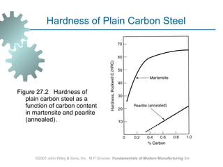
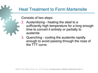
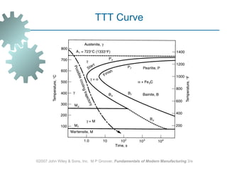
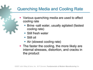
HEAT TREATMENT OF METALS Annealing Martensite Formation in Steel Precipitation Hardening Surface Hardening Heat Treatment Methods and Facilities ©2007 John Wiley & Sons, Inc.  M P Groover,  Fundamentals of Modern Manufacturing  3/e
Heat Treatment  Various heating and cooling processes performed to effect structural changes in a material, which in turn affect its mechanical properties  Most common applications are on  Metals  Similar treatments are performed on  Glass‑ceramics Tempered glass Powder metals and ceramics  ©2007 John Wiley & Sons, Inc.  M P Groover,  Fundamentals of Modern Manufacturing  3/e
Heat Treatment in Manufacturing Heat treatment operations are performed on metal workparts at various times during their manufacturing sequence  To soften a metal for forming prior to shaping To relieve strain hardening that occurs during forming To strengthen and harden the metal near the end of the manufacturing sequence ©2007 John Wiley & Sons, Inc.  M P Groover,  Fundamentals of Modern Manufacturing  3/e
Principal Heat Treatments  Annealing Martensite formation in steel Tempering of martensite Precipitation hardening Surface hardening  ©2007 John Wiley & Sons, Inc.  M P Groover,  Fundamentals of Modern Manufacturing  3/e
Annealing Heating and soaking metal at suitable temperature for a certain time, and slowly cooling  Reasons for annealing:  Reduce hardness and brittleness Alter microstructure to obtain desirable mechanical properties Soften metals to improve machinability or formability Recrystallize cold worked metals Relieve residual stresses induced by shaping ©2007 John Wiley & Sons, Inc.  M P Groover,  Fundamentals of Modern Manufacturing  3/e
Annealing of Steel Full annealing  - heating and soaking the alloy in the austenite region, followed by slow cooling to produce coarse pearlite  Usually associated with low and medium carbon steels Normalizing  - similar heating and soaking cycle as in full annealing, but faster cooling rates,  Results in fine pearlite, higher strength and hardness, but lower ductility ©2007 John Wiley & Sons, Inc.  M P Groover,  Fundamentals of Modern Manufacturing  3/e
Annealing to Reduce Work Hardening Cold worked parts are often annealed to reduce strain hardening and increase ductility by allowing strain‑hardened metal to recrystallize partially or completely  When annealing is performed to allow for further cold working of the part, it is called a  process anneal   When no subsequent deformation will be accomplished, it is simply called an  anneal ©2007 John Wiley & Sons, Inc.  M P Groover,  Fundamentals of Modern Manufacturing  3/e
Annealing for Stress-Relief Annealing operations are sometimes performed solely to relieve residual stresses caused by prior shape processing or fusion welding  Called  stress‑relief annealing   They help to reduce distortion and dimensional variations that might otherwise result in the stressed parts  ©2007 John Wiley & Sons, Inc.  M P Groover,  Fundamentals of Modern Manufacturing  3/e
Martensite Formation in Steel The iron‑carbon phase diagram shows the phases of iron and iron carbide under equilibrium conditions  Assumes cooling from high temperature is slow enough to permit austenite to transform into ferrite and cementite (Fe 3 C) mixture  However, under rapid cooling, so that equilibrium is prevented, austenite transforms into a nonequilibrium phase called  martensite , which is hard and brittle ©2007 John Wiley & Sons, Inc.  M P Groover,  Fundamentals of Modern Manufacturing  3/e
©2007 John Wiley & Sons, Inc.  M P Groover,  Fundamentals of Modern Manufacturing  3/e Iron-Carbon Phase Diagram
Figure 27.1  The TTT curve, showing transformation of austenite into other phases as function of time and temperature for a composition of about 0.80% C steel. Cooling trajectory shown yields martensite. ©2007 John Wiley & Sons, Inc.  M P Groover,  Fundamentals of Modern Manufacturing  3/e Time-Temperature-Transformation Curve
Martensite  A unique phase consisting of an iron‑carbon solution whose composition is the same as the austenite from which it was derived  Face‑centered cubic (FCC) structure of austenite is transformed into body‑centered tetragonal (BCT) structure of martensite The extreme hardness of martensite results from the lattice strain created by carbon atoms trapped in the BCT structure, thus providing a barrier to slip  ©2007 John Wiley & Sons, Inc.  M P Groover,  Fundamentals of Modern Manufacturing  3/e
Figure 27.2  Hardness of plain carbon steel as a function of carbon content in martensite and pearlite (annealed). ©2007 John Wiley & Sons, Inc.  M P Groover,  Fundamentals of Modern Manufacturing  3/e Hardness of Plain Carbon Steel
Heat Treatment to Form Martensite  Consists of two steps: Austenitizing - heating the steel to a sufficiently high temperature for a long enough time to convert it entirely or partially to austenite Quenching - cooling the austenite rapidly enough to avoid passing through the nose of the TTT curve  ©2007 John Wiley & Sons, Inc.  M P Groover,  Fundamentals of Modern Manufacturing  3/e
©2007 John Wiley & Sons, Inc.  M P Groover,  Fundamentals of Modern Manufacturing  3/e TTT Curve
Quenching Media and Cooling Rate  Various quenching media are used to affect cooling rate  Brine -salt water, usually agitated (fastest cooling rate) Still fresh water Still oil Air (slowest cooling rate) The faster the cooling, the more likely are internal stresses, distortion, and cracks in the product  ©2007 John Wiley & Sons, Inc.  M P Groover,  Fundamentals of Modern Manufacturing  3/e
Tempering of Martensite A heat treatment applied to martensite to reduce brittleness, increase toughness, and relieve stresses  Treatment involves heating and soaking at a temperature below the eutectoid for about one hour, followed by slow cooling  Results in precipitation of very fine carbide particles from the martensite iron‑carbon solution, gradually transforming the crystal structure from BCT to BCC  New structure is called  tempered martensite   ©2007 John Wiley & Sons, Inc.  M P Groover,  Fundamentals of Modern Manufacturing  3/e
Hardenability  The relative capacity of a steel to be hardened by transformation to martensite  It determines the depth below the quenched surface to which the steel is hardened  Steels with good hardenability can be hardened more deeply below the surface and do not require high cooling rates  Hardenability does not refer to the maximum hardness that can be attained ©2007 John Wiley & Sons, Inc.  M P Groover,  Fundamentals of Modern Manufacturing  3/e
Hardenability  Hardenability of steel is increased through alloying  Alloying elements having the greatest effect are chromium, manganese, molybdenum The mechanism by which these alloying elements work is to extend the time before the start of the austenite‑to‑pearlite transformation  In effect, the TTT curve is moved to the right, thus permitting slower quenching rates ©2007 John Wiley & Sons, Inc.  M P Groover,  Fundamentals of Modern Manufacturing  3/e
Figure 27.4  Jominy end‑quench test: (a) setup, showing end quench of the test specimen; and (b) typical pattern of hardness readings as a function of distance from quenched end. ©2007 John Wiley & Sons, Inc.  M P Groover,  Fundamentals of Modern Manufacturing  3/e Jominy End-Quench Test for Hardenability
Precipitation Hardening Heat treatment that precipitates fine particles that block the movement of dislocations and thus strengthen and harden the metal  Principal heat treatment for strengthening alloys of aluminum, copper, magnesium, nickel, and other nonferrous metals  Also utilized to strengthen a number of steel alloys that cannot form martensite by the usual heat treatment  ©2007 John Wiley & Sons, Inc.  M P Groover,  Fundamentals of Modern Manufacturing  3/e
Conditions for Precipitation Hardening The necessary condition for whether an alloy system can be strengthened by precipitation hardening is the presence of sloping solvus line in the phase diagram  A composition in this system that can be precipitation hardened is one that contains two equilibrium phases at room temperature, but which can be heated to a temperature that dissolves the second phase  ©2007 John Wiley & Sons, Inc.  M P Groover,  Fundamentals of Modern Manufacturing  3/e
Figure 27.5  Precipitation hardening: (a) phase diagram of an alloy system consisting of metals A and B that can be precipitation hardened; and (b) heat treatment: (1) solution treatment, (2) quenching, and (3) precipitation treatment . ©2007 John Wiley & Sons, Inc.  M P Groover,  Fundamentals of Modern Manufacturing  3/e Precipitation Hardening
Sequence in Precipitation Hardening Solution treatment - alloy is heated to a temperature  T s  above the solvus line into the alpha phase region and held for a period sufficient to dissolve the beta phase Quenching - to room temperature to create a supersaturated solid solution Precipitation treatment - alloy is heated to a temperature  T p , below  T s , to cause precipitation of fine particles of the beta phase  ©2007 John Wiley & Sons, Inc.  M P Groover,  Fundamentals of Modern Manufacturing  3/e
Surface Hardening Thermochemical treatments applied to steels in which the composition of the part surface is altered by adding various elements  Often called  case hardening   Most common treatments are carburizing, nitriding, and carbonitriding  Commonly applied to low carbon steel parts to achieve a hard, wear‑resistant outer shell while retaining a tough inner core  ©2007 John Wiley & Sons, Inc.  M P Groover,  Fundamentals of Modern Manufacturing  3/e
Carburizing Heating a part of low carbon steel in a carbon-rich environment so that C is diffused into surface  In effect the surface is converted to a high carbon steel, capable of higher hardness than the low‑C core Carburizing followed by quenching produces a case hardness of around HRC = 60 Internal regions are low-C steel, with low hardenability, so it is unaffected by quench and remains relatively tough and ductile Most common surface hardening treatment ©2007 John Wiley & Sons, Inc.  M P Groover,  Fundamentals of Modern Manufacturing  3/e
Nitriding Treatment in which nitrogen is diffused into surface of special alloy steels to produce a thin hard casing without quenching Carried out at around 500  C (950  F)  To be most effective, steel must have alloying ingredients such as aluminum or chromium to form nitride compounds that precipitate as very fine particles in the casing to harden the steel  Hardness up to HRC 70  ©2007 John Wiley & Sons, Inc.  M P Groover,  Fundamentals of Modern Manufacturing  3/e
Chromizing  Requires higher temperatures and longer treatment times than the preceding hardening treatments Usually applied to low carbon steels Casing is not only hard and wear resistant; it is also heat and corrosion resistant ©2007 John Wiley & Sons, Inc.  M P Groover,  Fundamentals of Modern Manufacturing  3/e
Furnaces for Heat Treatment Fuel‑fired furnaces  Normally direct‑fired - the work is exposed directly to combustion products  Fuels: natural gas or propane and fuel oils that can be atomized  Electric furnaces Electric resistance for heating  Cleaner, quieter, and more uniform heating More expensive to purchase and operate  ©2007 John Wiley & Sons, Inc.  M P Groover,  Fundamentals of Modern Manufacturing  3/e
Batch vs. Continuous Furnaces Batch furnaces  Heating system in an insulated chamber, with a door for loading and unloading  Production in batches Continuous furnaces  Generally for higher production rates  Mechanisms for transporting work through furnace include rotating hearths and straight‑through conveyors ©2007 John Wiley & Sons, Inc.  M P Groover,  Fundamentals of Modern Manufacturing  3/e
Other Furnace Types Atmospheric control furnaces Desirable in conventional heat treatment to avoid excessive oxidation or decarburization  Include C and/or N rich environments for diffusion into work surface  Vacuum furnaces  Radiant energy is used to heat the parts  Disadvantage: time needed each cycle to draw vacuum  ©2007 John Wiley & Sons, Inc.  M P Groover,  Fundamentals of Modern Manufacturing  3/e
Selective Surface Hardening Methods These methods heat only the work surface, or local areas of the work surface  They differ from surface hardening methods in that no chemical changes occur Methods include:  Flame hardening Induction hardening High‑frequency resistance heating Electron beam heating Laser beam heating  ©2007 John Wiley & Sons, Inc.  M P Groover,  Fundamentals of Modern Manufacturing  3/e
Flame Hardening Heating of work surface by one or more torches followed by rapid quenching  Applied to carbon and alloy steels, tool steels, and cast irons  Fuels include acetylene (C 2 H 2 ), propane (C 3 H 8 ), and other gases  Lends itself to high production as well as big components such as large gears that exceed the size capacity of furnaces   ©2007 John Wiley & Sons, Inc.  M P Groover,  Fundamentals of Modern Manufacturing  3/e
Induction Heating Application of electromagnetically induced energy supplied by an induction coil to an electrically conductive workpart  Widely used for brazing, soldering, adhesive curing, and various heat treatments  When used for steel hardening treatments, quenching follows heating  Cycle times are short, so process lends itself to high production  ©2007 John Wiley & Sons, Inc.  M P Groover,  Fundamentals of Modern Manufacturing  3/e
Figure 27.7  Typical induction heating setup. High frequency alternating current in a coil induces current in the workpart to effect heating. ©2007 John Wiley & Sons, Inc.  M P Groover,  Fundamentals of Modern Manufacturing  3/e Induction Heating
High‑frequency (HF) Resistance Heating Used to harden specific areas of steel work surfaces by application of localized resistance heating at high frequency (400 kHz typical)  Contacts are attached to workpart at outer edges of the area  When HF current is applied, region under conductor is heated quickly to high temperature ‑ heating to austenite range typically takes less than a second  When power is turned off, area is quenched by heat transfer to the surrounding metal  ©2007 John Wiley & Sons, Inc.  M P Groover,  Fundamentals of Modern Manufacturing  3/e
Figure 27.8  Typical setup for high‑frequency resistance heating. ©2007 John Wiley & Sons, Inc.  M P Groover,  Fundamentals of Modern Manufacturing  3/e High‑frequency Resistance Heating
Electron Beam (EB) Heating Electron beam focused onto small area, resulting in rapid heat buildup  Involves localized surface hardening of steel - high energy densities in a small region of part so that austenitizing temperatures can be achieved often in less than a second When beam is removed, heated area is immediately quenched and hardened by heat transfer to surrounding metal Disadvantage: best results are achieved when performed in a vacuum ©2007 John Wiley & Sons, Inc.  M P Groover,  Fundamentals of Modern Manufacturing  3/e
Laser Beam (LB) Heating High‑density beam of coherent light focused on a small area ‑ the beam is usually moved along a defined path on the work surface  Laser  - acronym for light amplification by stimulated emission of radiation When beam is moved, area is immediately quenched by heat conduction to surrounding metal  Advantage of LB over EB heating is that laser beams do not require a vacuum ©2007 John Wiley & Sons, Inc.  M P Groover,  Fundamentals of Modern Manufacturing  3/e

Ch27 1

  • 1.
    HEAT TREATMENT OFMETALS Annealing Martensite Formation in Steel Precipitation Hardening Surface Hardening Heat Treatment Methods and Facilities ©2007 John Wiley & Sons, Inc. M P Groover, Fundamentals of Modern Manufacturing 3/e
  • 2.
    Heat Treatment Various heating and cooling processes performed to effect structural changes in a material, which in turn affect its mechanical properties Most common applications are on Metals Similar treatments are performed on Glass‑ceramics Tempered glass Powder metals and ceramics ©2007 John Wiley & Sons, Inc. M P Groover, Fundamentals of Modern Manufacturing 3/e
  • 3.
    Heat Treatment inManufacturing Heat treatment operations are performed on metal workparts at various times during their manufacturing sequence To soften a metal for forming prior to shaping To relieve strain hardening that occurs during forming To strengthen and harden the metal near the end of the manufacturing sequence ©2007 John Wiley & Sons, Inc. M P Groover, Fundamentals of Modern Manufacturing 3/e
  • 4.
    Principal Heat Treatments Annealing Martensite formation in steel Tempering of martensite Precipitation hardening Surface hardening ©2007 John Wiley & Sons, Inc. M P Groover, Fundamentals of Modern Manufacturing 3/e
  • 5.
    Annealing Heating andsoaking metal at suitable temperature for a certain time, and slowly cooling Reasons for annealing: Reduce hardness and brittleness Alter microstructure to obtain desirable mechanical properties Soften metals to improve machinability or formability Recrystallize cold worked metals Relieve residual stresses induced by shaping ©2007 John Wiley & Sons, Inc. M P Groover, Fundamentals of Modern Manufacturing 3/e
  • 6.
    Annealing of SteelFull annealing - heating and soaking the alloy in the austenite region, followed by slow cooling to produce coarse pearlite Usually associated with low and medium carbon steels Normalizing - similar heating and soaking cycle as in full annealing, but faster cooling rates, Results in fine pearlite, higher strength and hardness, but lower ductility ©2007 John Wiley & Sons, Inc. M P Groover, Fundamentals of Modern Manufacturing 3/e
  • 7.
    Annealing to ReduceWork Hardening Cold worked parts are often annealed to reduce strain hardening and increase ductility by allowing strain‑hardened metal to recrystallize partially or completely When annealing is performed to allow for further cold working of the part, it is called a process anneal When no subsequent deformation will be accomplished, it is simply called an anneal ©2007 John Wiley & Sons, Inc. M P Groover, Fundamentals of Modern Manufacturing 3/e
  • 8.
    Annealing for Stress-ReliefAnnealing operations are sometimes performed solely to relieve residual stresses caused by prior shape processing or fusion welding Called stress‑relief annealing They help to reduce distortion and dimensional variations that might otherwise result in the stressed parts ©2007 John Wiley & Sons, Inc. M P Groover, Fundamentals of Modern Manufacturing 3/e
  • 9.
    Martensite Formation inSteel The iron‑carbon phase diagram shows the phases of iron and iron carbide under equilibrium conditions Assumes cooling from high temperature is slow enough to permit austenite to transform into ferrite and cementite (Fe 3 C) mixture However, under rapid cooling, so that equilibrium is prevented, austenite transforms into a nonequilibrium phase called martensite , which is hard and brittle ©2007 John Wiley & Sons, Inc. M P Groover, Fundamentals of Modern Manufacturing 3/e
  • 10.
    ©2007 John Wiley& Sons, Inc. M P Groover, Fundamentals of Modern Manufacturing 3/e Iron-Carbon Phase Diagram
  • 11.
    Figure 27.1 The TTT curve, showing transformation of austenite into other phases as function of time and temperature for a composition of about 0.80% C steel. Cooling trajectory shown yields martensite. ©2007 John Wiley & Sons, Inc. M P Groover, Fundamentals of Modern Manufacturing 3/e Time-Temperature-Transformation Curve
  • 12.
    Martensite Aunique phase consisting of an iron‑carbon solution whose composition is the same as the austenite from which it was derived Face‑centered cubic (FCC) structure of austenite is transformed into body‑centered tetragonal (BCT) structure of martensite The extreme hardness of martensite results from the lattice strain created by carbon atoms trapped in the BCT structure, thus providing a barrier to slip ©2007 John Wiley & Sons, Inc. M P Groover, Fundamentals of Modern Manufacturing 3/e
  • 13.
    Figure 27.2 Hardness of plain carbon steel as a function of carbon content in martensite and pearlite (annealed). ©2007 John Wiley & Sons, Inc. M P Groover, Fundamentals of Modern Manufacturing 3/e Hardness of Plain Carbon Steel
  • 14.
    Heat Treatment toForm Martensite Consists of two steps: Austenitizing - heating the steel to a sufficiently high temperature for a long enough time to convert it entirely or partially to austenite Quenching - cooling the austenite rapidly enough to avoid passing through the nose of the TTT curve ©2007 John Wiley & Sons, Inc. M P Groover, Fundamentals of Modern Manufacturing 3/e
  • 15.
    ©2007 John Wiley& Sons, Inc. M P Groover, Fundamentals of Modern Manufacturing 3/e TTT Curve
  • 16.
    Quenching Media andCooling Rate Various quenching media are used to affect cooling rate Brine -salt water, usually agitated (fastest cooling rate) Still fresh water Still oil Air (slowest cooling rate) The faster the cooling, the more likely are internal stresses, distortion, and cracks in the product ©2007 John Wiley & Sons, Inc. M P Groover, Fundamentals of Modern Manufacturing 3/e
  • 17.
    Tempering of MartensiteA heat treatment applied to martensite to reduce brittleness, increase toughness, and relieve stresses Treatment involves heating and soaking at a temperature below the eutectoid for about one hour, followed by slow cooling Results in precipitation of very fine carbide particles from the martensite iron‑carbon solution, gradually transforming the crystal structure from BCT to BCC New structure is called tempered martensite ©2007 John Wiley & Sons, Inc. M P Groover, Fundamentals of Modern Manufacturing 3/e
  • 18.
    Hardenability Therelative capacity of a steel to be hardened by transformation to martensite It determines the depth below the quenched surface to which the steel is hardened Steels with good hardenability can be hardened more deeply below the surface and do not require high cooling rates Hardenability does not refer to the maximum hardness that can be attained ©2007 John Wiley & Sons, Inc. M P Groover, Fundamentals of Modern Manufacturing 3/e
  • 19.
    Hardenability Hardenabilityof steel is increased through alloying Alloying elements having the greatest effect are chromium, manganese, molybdenum The mechanism by which these alloying elements work is to extend the time before the start of the austenite‑to‑pearlite transformation In effect, the TTT curve is moved to the right, thus permitting slower quenching rates ©2007 John Wiley & Sons, Inc. M P Groover, Fundamentals of Modern Manufacturing 3/e
  • 20.
    Figure 27.4 Jominy end‑quench test: (a) setup, showing end quench of the test specimen; and (b) typical pattern of hardness readings as a function of distance from quenched end. ©2007 John Wiley & Sons, Inc. M P Groover, Fundamentals of Modern Manufacturing 3/e Jominy End-Quench Test for Hardenability
  • 21.
    Precipitation Hardening Heattreatment that precipitates fine particles that block the movement of dislocations and thus strengthen and harden the metal Principal heat treatment for strengthening alloys of aluminum, copper, magnesium, nickel, and other nonferrous metals Also utilized to strengthen a number of steel alloys that cannot form martensite by the usual heat treatment ©2007 John Wiley & Sons, Inc. M P Groover, Fundamentals of Modern Manufacturing 3/e
  • 22.
    Conditions for PrecipitationHardening The necessary condition for whether an alloy system can be strengthened by precipitation hardening is the presence of sloping solvus line in the phase diagram A composition in this system that can be precipitation hardened is one that contains two equilibrium phases at room temperature, but which can be heated to a temperature that dissolves the second phase ©2007 John Wiley & Sons, Inc. M P Groover, Fundamentals of Modern Manufacturing 3/e
  • 23.
    Figure 27.5 Precipitation hardening: (a) phase diagram of an alloy system consisting of metals A and B that can be precipitation hardened; and (b) heat treatment: (1) solution treatment, (2) quenching, and (3) precipitation treatment . ©2007 John Wiley & Sons, Inc. M P Groover, Fundamentals of Modern Manufacturing 3/e Precipitation Hardening
  • 24.
    Sequence in PrecipitationHardening Solution treatment - alloy is heated to a temperature T s above the solvus line into the alpha phase region and held for a period sufficient to dissolve the beta phase Quenching - to room temperature to create a supersaturated solid solution Precipitation treatment - alloy is heated to a temperature T p , below T s , to cause precipitation of fine particles of the beta phase ©2007 John Wiley & Sons, Inc. M P Groover, Fundamentals of Modern Manufacturing 3/e
  • 25.
    Surface Hardening Thermochemicaltreatments applied to steels in which the composition of the part surface is altered by adding various elements Often called case hardening Most common treatments are carburizing, nitriding, and carbonitriding Commonly applied to low carbon steel parts to achieve a hard, wear‑resistant outer shell while retaining a tough inner core ©2007 John Wiley & Sons, Inc. M P Groover, Fundamentals of Modern Manufacturing 3/e
  • 26.
    Carburizing Heating apart of low carbon steel in a carbon-rich environment so that C is diffused into surface In effect the surface is converted to a high carbon steel, capable of higher hardness than the low‑C core Carburizing followed by quenching produces a case hardness of around HRC = 60 Internal regions are low-C steel, with low hardenability, so it is unaffected by quench and remains relatively tough and ductile Most common surface hardening treatment ©2007 John Wiley & Sons, Inc. M P Groover, Fundamentals of Modern Manufacturing 3/e
  • 27.
    Nitriding Treatment inwhich nitrogen is diffused into surface of special alloy steels to produce a thin hard casing without quenching Carried out at around 500  C (950  F) To be most effective, steel must have alloying ingredients such as aluminum or chromium to form nitride compounds that precipitate as very fine particles in the casing to harden the steel Hardness up to HRC 70 ©2007 John Wiley & Sons, Inc. M P Groover, Fundamentals of Modern Manufacturing 3/e
  • 28.
    Chromizing Requireshigher temperatures and longer treatment times than the preceding hardening treatments Usually applied to low carbon steels Casing is not only hard and wear resistant; it is also heat and corrosion resistant ©2007 John Wiley & Sons, Inc. M P Groover, Fundamentals of Modern Manufacturing 3/e
  • 29.
    Furnaces for HeatTreatment Fuel‑fired furnaces Normally direct‑fired - the work is exposed directly to combustion products Fuels: natural gas or propane and fuel oils that can be atomized Electric furnaces Electric resistance for heating Cleaner, quieter, and more uniform heating More expensive to purchase and operate ©2007 John Wiley & Sons, Inc. M P Groover, Fundamentals of Modern Manufacturing 3/e
  • 30.
    Batch vs. ContinuousFurnaces Batch furnaces Heating system in an insulated chamber, with a door for loading and unloading Production in batches Continuous furnaces Generally for higher production rates Mechanisms for transporting work through furnace include rotating hearths and straight‑through conveyors ©2007 John Wiley & Sons, Inc. M P Groover, Fundamentals of Modern Manufacturing 3/e
  • 31.
    Other Furnace TypesAtmospheric control furnaces Desirable in conventional heat treatment to avoid excessive oxidation or decarburization Include C and/or N rich environments for diffusion into work surface Vacuum furnaces Radiant energy is used to heat the parts Disadvantage: time needed each cycle to draw vacuum ©2007 John Wiley & Sons, Inc. M P Groover, Fundamentals of Modern Manufacturing 3/e
  • 32.
    Selective Surface HardeningMethods These methods heat only the work surface, or local areas of the work surface They differ from surface hardening methods in that no chemical changes occur Methods include: Flame hardening Induction hardening High‑frequency resistance heating Electron beam heating Laser beam heating ©2007 John Wiley & Sons, Inc. M P Groover, Fundamentals of Modern Manufacturing 3/e
  • 33.
    Flame Hardening Heatingof work surface by one or more torches followed by rapid quenching Applied to carbon and alloy steels, tool steels, and cast irons Fuels include acetylene (C 2 H 2 ), propane (C 3 H 8 ), and other gases Lends itself to high production as well as big components such as large gears that exceed the size capacity of furnaces ©2007 John Wiley & Sons, Inc. M P Groover, Fundamentals of Modern Manufacturing 3/e
  • 34.
    Induction Heating Applicationof electromagnetically induced energy supplied by an induction coil to an electrically conductive workpart Widely used for brazing, soldering, adhesive curing, and various heat treatments When used for steel hardening treatments, quenching follows heating Cycle times are short, so process lends itself to high production ©2007 John Wiley & Sons, Inc. M P Groover, Fundamentals of Modern Manufacturing 3/e
  • 35.
    Figure 27.7 Typical induction heating setup. High frequency alternating current in a coil induces current in the workpart to effect heating. ©2007 John Wiley & Sons, Inc. M P Groover, Fundamentals of Modern Manufacturing 3/e Induction Heating
  • 36.
    High‑frequency (HF) ResistanceHeating Used to harden specific areas of steel work surfaces by application of localized resistance heating at high frequency (400 kHz typical) Contacts are attached to workpart at outer edges of the area When HF current is applied, region under conductor is heated quickly to high temperature ‑ heating to austenite range typically takes less than a second When power is turned off, area is quenched by heat transfer to the surrounding metal ©2007 John Wiley & Sons, Inc. M P Groover, Fundamentals of Modern Manufacturing 3/e
  • 37.
    Figure 27.8 Typical setup for high‑frequency resistance heating. ©2007 John Wiley & Sons, Inc. M P Groover, Fundamentals of Modern Manufacturing 3/e High‑frequency Resistance Heating
  • 38.
    Electron Beam (EB)Heating Electron beam focused onto small area, resulting in rapid heat buildup Involves localized surface hardening of steel - high energy densities in a small region of part so that austenitizing temperatures can be achieved often in less than a second When beam is removed, heated area is immediately quenched and hardened by heat transfer to surrounding metal Disadvantage: best results are achieved when performed in a vacuum ©2007 John Wiley & Sons, Inc. M P Groover, Fundamentals of Modern Manufacturing 3/e
  • 39.
    Laser Beam (LB)Heating High‑density beam of coherent light focused on a small area ‑ the beam is usually moved along a defined path on the work surface Laser - acronym for light amplification by stimulated emission of radiation When beam is moved, area is immediately quenched by heat conduction to surrounding metal Advantage of LB over EB heating is that laser beams do not require a vacuum ©2007 John Wiley & Sons, Inc. M P Groover, Fundamentals of Modern Manufacturing 3/e