An Approximate Analysis Procedure for Piled Raft subjected to Vertical Loading
•
1 like•714 views

Piled raft is a geotechnical composite construction consisting of three elements raft, piles and soil. Addition of piles in raft strategically improves ultimate load carrying capacity, decreases overall and differential settlement .The design of piled raft is complicated due to complex interaction between rafts, pile and soil. In recent years due to advent of multistory buildings there has been a significant rise in usage of piled raft in India. This paper presents a simplified method for analysis of piled raft with use of software SAFE considering all the interactions. In the scope of this paper, the design procedure for piled rafts is discussed and results are verified with that available from literature.
![An Approximate Analysis Procedure for Piled Raft subjected to Vertical Loading
(IJSRD/Vol. 1/Issue 8/2013/0004)
All rights reserved by www.ijsrd.com 1540
D
L
L
L
D
L
L
L
dGW
P
Lt
t
)tanh(
)1(
8
1
)tanh(2
)1(
2
ro = Radius of pile m
rm= Radius at which deflections in soil are assumed to be
vanishingly small
= ln[{0.25+(2.5ρ(1-μ)ξ}2L/d]
= ln[5ρ(1-μ)L/d] for ξ=1
GL = Shear modulus at pile base kN/m2
Gb= Shear modulus just below pile base kN/m2
G = Average shear modulus of soil over embedment depth,
L, of pile kN/m2
.
ξ= GL/Gb(Ratio of end bearings for end bearing piles)
ρ =G/GL(Variation of shear modulus with depth)
λ = Ep/GL (Measure of Pile compressibility)
η = db/d (ratio of diameter at base to top)
= ln(2rm/d) (measure of radius of influence of pile)
μL = 2 x (L/d) (measure of pile compressibility)
Pt = Load on Pile
Wt = Deflection on Pile
Fig. 3: Assumed variation of Soil Shear Modulus with
Depth
III. STIFFNESS OF PILE GROUP
For a given load per pile, piles in a group lying below a pile
cap will settle more than corresponding isolated pile. The
decreasing stiffness can be quantified by means of
efficiency factor ηw. The stiffness of pile group Kpg may be
expressed as a fraction, ηw ,of the sum of the individual pile
stiffness Kp. Thus for a group of n piles
Kpg = ηw n Kp
ηw = 1/Rsv
Rsv = (Settlement of Pile Group / Settlement of Single pile
under average load)
IV. SETTLEMENT OF PILE GROUP
One of the common means of analysing pile group
behaviour is viz the interaction factor method described by
Poulos and Davis6
. The use of interaction factor method
may be regarded as equivalent to superimposing the separate
deformation fields that each pile would give rise to by itself,
in order to arrive at overall deformations. In this method, the
settlement ρi of a pile i within a group of n piles is given as
follows
Where,
Pj = load in pile j
ρo = settlement of a single pile under unit load
αij = interaction factor for pile i due to any other pile j within
the group, corresponding to the spacing sij between piles
i and j.
It has been found that the interaction factor α can be
approximated as follows 4
A, B- factors
s= c/c spacing of Piles
d = diameter of Piles
A = A1 x Ab x Ak
B = B1 x Bb x Bk
Where,
A1 , B1 = Factor depending on ratio of length L to diameter
d
Ab , Bb = Factor depending on ratio of modulus of bearing
stratum to soil along shaft
Ak , Bk = Factor depending on ratio of pile stiffness to soil
stiffness
Via curve fitting, following expressions were obtained for
above factors.
A1 = 0.376 + 0.0014(L/d) - 0.00002(L/d) 2
Ab = 1.254 - 0.326 ln(Eb/Es)
Ak = 0.099 + 0.126 ln(K)
B1 = 0.116 - 0.0164(L/d)
Bb = 0.865 + 0.164 ln(Eb/Es)
Bk = 1.409 - 0.055(K)
Where,
L = Pile Length
d = Pile Diameter
Eb = Average modulus of bearing stratum below pile tip
Es = Average soil modulus along pile shaft
K = Pile Stiffness factor = Ep x Ra/Es
Ra = area ratio (=1 for solid pile)
V. STIFFNESS OF PILED RAFT
The stiffness of the piled raft foundation can be estimated as
follows:
Kpr = (Kpg + Kr (1- 2αrp)) / (1-αrp
2
Kr / Kpg)
Where,
Kpr = stiffness of Piled raft
Kpg = stiffness of the pile group
Kr = stiffness of the raft alone
αrp = raft – pile interaction factor
αrp = 1 – ln (dr / dp) / ζ
where
dr = average diameter of pile cap, (corresponding to an area
equal to the raft area divided by number of piles)
VI. PROCEDURE FOR THE PROPOSED PLATE ON
SPRING APPROACH
The procedure for the analysis of piled raft foundation is
determined as follows](data:image/gif;base64,R0lGODlhAQABAIAAAAAAAP///yH5BAEAAAAALAAAAAABAAEAAAIBRAA7)
Recommended
Recommended
More Related Content
What's hot
What's hot (20)
Viewers also liked
Similar to An Approximate Analysis Procedure for Piled Raft subjected to Vertical Loading
Similar to An Approximate Analysis Procedure for Piled Raft subjected to Vertical Loading (20)
More from ijsrd.com
More from ijsrd.com (20)
Recently uploaded
Recently uploaded (20)
An Approximate Analysis Procedure for Piled Raft subjected to Vertical Loading
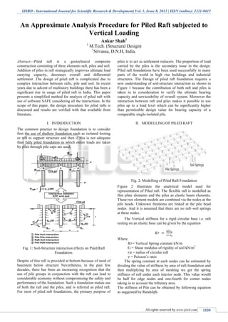
- 1. IJSRD - International Journal for Scientific Research & Development| Vol. 1, Issue 8, 2013 | ISSN (online): 2321-0613 All rights reserved by www.ijsrd.com 1539 An Approximate Analysis Procedure for Piled Raft subjected to Vertical Loading Ankur Shah1 1 M.Tech. (Structural Design) 1 Silvassa, D.N.H, India. Abstract—Piled raft is a geotechnical composite construction consisting of three elements raft, piles and soil. Addition of piles in raft strategically improves ultimate load carrying capacity, decreases overall and differential settlement .The design of piled raft is complicated due to complex interaction between rafts, pile and soil. In recent years due to advent of multistory buildings there has been a significant rise in usage of piled raft in India. This paper presents a simplified method for analysis of piled raft with use of software SAFE considering all the interactions. In the scope of this paper, the design procedure for piled rafts is discussed and results are verified with that available from literature. I. INTRODUCTION The common practice to design foundation is to consider first the use of shallow foundation such as isolated footing or raft to support structure and then if this is not adequate than fully piled foundation in which entire loads are taken by piles through pile caps are used. Fig. 1: Soil-Structure interaction effects on Piled Raft Foundation. Despite of this raft is provided at bottom because of need of basement below structure Nevertheless, in the past few decades, there has been an increasing recognition that the use of pile groups in conjunction with the raft can lead to considerable economy without compromising the safety and performance of the foundation. Such a foundation makes use of both the raft and the piles, and is referred as piled raft. For most of piled raft foundations, the primary purpose of piles is to act as settlement reducers. The proportion of load carried by the piles is the secondary issue in the design. Piled raft foundations have been used successfully in many parts of the world in high rise buildings and industrial structures. The Design of piled raft foundation requires a new understanding of soil-structure interaction as shown in Figure 1 because the contribution of both raft and piles is taken in to consideration to verify the ultimate bearing capacity and serviceability of overall system. Moreover the interaction between raft and piles makes it possible to use piles up to a load level which can be significantly higher than permissible design value for bearing capacity of a comparable single-isolated pile. II. MODELLING OF PILED RAFT Fig. 2: Modelling of Piled Raft Foundation Figure 2 illustrates the analytical model used for representation of Piled raft. The flexible raft is modelled as thin plate elements and the piles as elastic beam elements. These two element models are combined via the nodes at the pile heads. Unknown freedoms are linked at the pile head nodes. And it is assumed that there are no raft–soil springs at these nodes. The Vertical stiffness for a rigid circular base i.e. raft resting on an elastic base can be given by the equation Where = Vertical Spring constant kN/m G = Shear modulus of rigidity of soil kN/m2 = radius of circular raft = Poisson’s ratio The spring constant at each nodes can be estimated by dividing the value of stiffness by area of raft foundation and then multiplying by area of meshing we get the spring stiffness of raft under each interior node. This value would be half for edge nodes and one-fourth for corner nodes taking in to account the tributary area. The stiffness of Pile can be obtained by following equation as suggested by Randolph.
- 2. An Approximate Analysis Procedure for Piled Raft subjected to Vertical Loading (IJSRD/Vol. 1/Issue 8/2013/0004) All rights reserved by www.ijsrd.com 1540 D L L L D L L L dGW P Lt t )tanh( )1( 8 1 )tanh(2 )1( 2 ro = Radius of pile m rm= Radius at which deflections in soil are assumed to be vanishingly small = ln[{0.25+(2.5ρ(1-μ)ξ}2L/d] = ln[5ρ(1-μ)L/d] for ξ=1 GL = Shear modulus at pile base kN/m2 Gb= Shear modulus just below pile base kN/m2 G = Average shear modulus of soil over embedment depth, L, of pile kN/m2 . ξ= GL/Gb(Ratio of end bearings for end bearing piles) ρ =G/GL(Variation of shear modulus with depth) λ = Ep/GL (Measure of Pile compressibility) η = db/d (ratio of diameter at base to top) = ln(2rm/d) (measure of radius of influence of pile) μL = 2 x (L/d) (measure of pile compressibility) Pt = Load on Pile Wt = Deflection on Pile Fig. 3: Assumed variation of Soil Shear Modulus with Depth III. STIFFNESS OF PILE GROUP For a given load per pile, piles in a group lying below a pile cap will settle more than corresponding isolated pile. The decreasing stiffness can be quantified by means of efficiency factor ηw. The stiffness of pile group Kpg may be expressed as a fraction, ηw ,of the sum of the individual pile stiffness Kp. Thus for a group of n piles Kpg = ηw n Kp ηw = 1/Rsv Rsv = (Settlement of Pile Group / Settlement of Single pile under average load) IV. SETTLEMENT OF PILE GROUP One of the common means of analysing pile group behaviour is viz the interaction factor method described by Poulos and Davis6 . The use of interaction factor method may be regarded as equivalent to superimposing the separate deformation fields that each pile would give rise to by itself, in order to arrive at overall deformations. In this method, the settlement ρi of a pile i within a group of n piles is given as follows Where, Pj = load in pile j ρo = settlement of a single pile under unit load αij = interaction factor for pile i due to any other pile j within the group, corresponding to the spacing sij between piles i and j. It has been found that the interaction factor α can be approximated as follows 4 A, B- factors s= c/c spacing of Piles d = diameter of Piles A = A1 x Ab x Ak B = B1 x Bb x Bk Where, A1 , B1 = Factor depending on ratio of length L to diameter d Ab , Bb = Factor depending on ratio of modulus of bearing stratum to soil along shaft Ak , Bk = Factor depending on ratio of pile stiffness to soil stiffness Via curve fitting, following expressions were obtained for above factors. A1 = 0.376 + 0.0014(L/d) - 0.00002(L/d) 2 Ab = 1.254 - 0.326 ln(Eb/Es) Ak = 0.099 + 0.126 ln(K) B1 = 0.116 - 0.0164(L/d) Bb = 0.865 + 0.164 ln(Eb/Es) Bk = 1.409 - 0.055(K) Where, L = Pile Length d = Pile Diameter Eb = Average modulus of bearing stratum below pile tip Es = Average soil modulus along pile shaft K = Pile Stiffness factor = Ep x Ra/Es Ra = area ratio (=1 for solid pile) V. STIFFNESS OF PILED RAFT The stiffness of the piled raft foundation can be estimated as follows: Kpr = (Kpg + Kr (1- 2αrp)) / (1-αrp 2 Kr / Kpg) Where, Kpr = stiffness of Piled raft Kpg = stiffness of the pile group Kr = stiffness of the raft alone αrp = raft – pile interaction factor αrp = 1 – ln (dr / dp) / ζ where dr = average diameter of pile cap, (corresponding to an area equal to the raft area divided by number of piles) VI. PROCEDURE FOR THE PROPOSED PLATE ON SPRING APPROACH The procedure for the analysis of piled raft foundation is determined as follows
- 3. An Approximate Analysis Procedure for Piled Raft subjected to Vertical Loading (IJSRD/Vol. 1/Issue 8/2013/0004) All rights reserved by www.ijsrd.com 1541 1) Determination of Stiffness of Raft foundation (raft-soil interaction) 2) Determination of Stiffness of Piled foundation considering (Pile-soil and pile-pile interactions) 3) Determination of Stiffness of Piled raft (pile-raft interaction) 4) Determination of reduced stiffness of individual piles 5) Determination of reduced stiffness of raft 6) Preparation of model in SAFE 7) Applying piles and soil as springs below raft represented as plate VII. ACCURACY OF THE PROPOSED PLATE ON SPRING APPROACH The Problem taken for verification of analysis is taken from paper “Method of analysis of piled raft foundation” 3 . The Raft taken is of size 10 x 6m. Pile diameter is 0.5 m and length 10 m. Load at P1 = 1000 kN and at P2 = 2000 kN. Total load= 12000 kN. Other Data are shown in Figure 4. Soil considered is homogeneous clayey soil. Fig. 4: Verification example of Piled raft Foundation The results are compared with software GARP3 and FLAC- 3D3 in Table 1 and the results obtained are satisfactory. The deformed Shape is shown in Fig. 5. Method Central Settlement mm Corner pile Settlement mm Max Raft Moment MNm /m % Load taken by Piles GARP 34.2 26 0.684 65.1 FLAC-3D 39.9 35.8 0.484 58.2 PROPOSED 37.5 29.9 0.566 62.8 Table.1: Comparison of results of plate on spring approach with GARP and FLAC-3D Fig. 5: Deformed Shape of Piled raft foundation VIII. CONCLUSION An approximate approach for the analysis of the deformation of piled raft foundation subjected to vertical loading has been developed. It also incorporates details regarding the structural design of pile and raft foundation. An important feature of the proposed method is that pile- pile, pile-soil, raft-soil and pile-raft interactions were incorporated for the analysis. REFERENCES [1] H.G. Poulos, Piled raft foundations: design and application, Geotechnique, Vol.51, No.2, pp.95-113, 2001. [2] H.G. Poulos, Practical design procedures for piled raft foundation, Design application of Raft foundation, pp.425-467, 2001. [3] H.G. Poulos, Method of analysis of piled raft foundation, ISSMGE, July 2001. [4] H.G. Poulos, Simulation of the performance and remediation of imperfect pile groups, Deep Foundations on Bored and Auger Piles, pp. 143-154, 2009. [5] R. Katzenbach, U. Arslan and C. Moorman, Piled raft foundation projects ingermany, Design application of Raft foundation, pp.323-391, 2001. [6] K. Fleming, A. Weltman, M. Randolph, K. Elson, Piling Engineereing,3rd edition, Taylor and Francis group ,New York,2009 [7] Poulos H.G. and Davis E.H. Pile Foundation Analysis and Design,3rd edition, John Wiley, New York,1980.