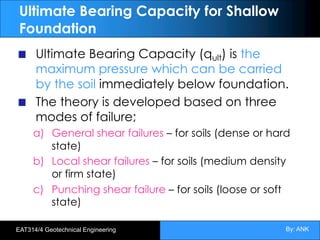
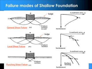
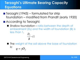
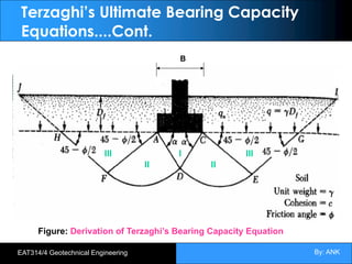
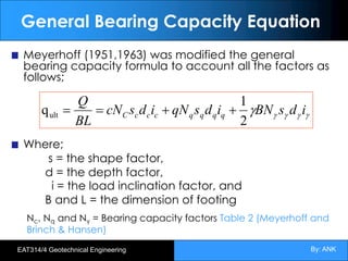
This document discusses shallow foundations and their bearing capacity. It defines shallow foundations as those that transfer loads to the soil at the base of the structure. The document then outlines Terzaghi's equations for calculating the ultimate bearing capacity of soils, including factors for cohesion, internal friction angle, soil unit weight, and foundation geometry. It also discusses factors of safety used to determine allowable bearing capacities and considerations for groundwater effects. Examples are provided to demonstrate calculating ultimate bearing capacities.


![By: ANK
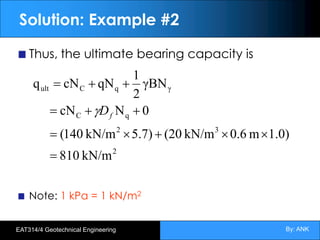
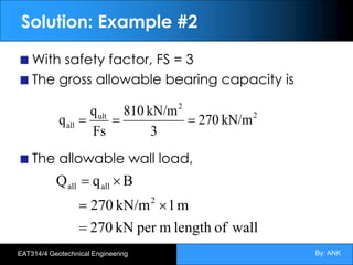
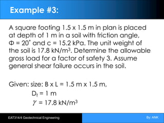
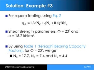
EAT314/4 Geotechnical Engineering
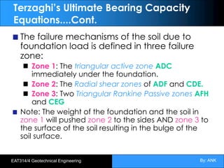
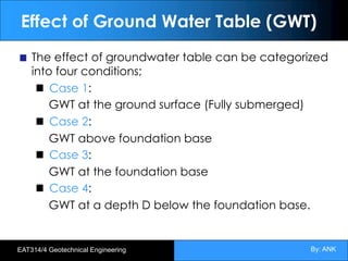
Case 4: GWT at a depth D below the
foundation base.
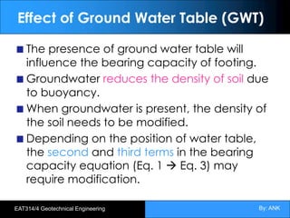
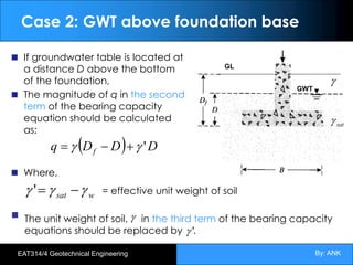
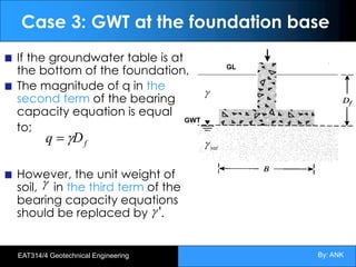
When the groundwater table is at a
depth D below the bottom of the
foundation,
The magnitude of q in the second
term of the bearing capacity
equation is equal to;
The magnitude of in the third term
of the bearing capacity equations
should be replaced by .
f
D
q g
=
( )
[ ] ( )
( )
B
D
For
B
D
For
'
1
>
=
£
-
+
=
g
g
g
g
g
av
av D
B
D
B
g
av
g
GL
GWT
g
sat
g](https://image.slidesharecdn.com/soilbearingcapacity-221211013717-a6e56f21/85/Soil-Bearing-Capacity-pdf-50-320.jpg)


![Geotechnical Engineering-II [Lec #17: Bearing Capacity of Soil]](https://cdn.slidesharecdn.com/ss_thumbnails/17-181123045836-thumbnail.jpg?width=640&height=640&fit=bounds)
![Geotechnical Engineering-II [Lec #18: Terzaghi Bearing Capacity Equation]](https://cdn.slidesharecdn.com/ss_thumbnails/18-181123045854-thumbnail.jpg?width=640&height=640&fit=bounds)


![Geotechnical Engineering-II [Lec #19: General Bearing Capacity Equation]](https://cdn.slidesharecdn.com/ss_thumbnails/19-181123045917-thumbnail.jpg?width=640&height=640&fit=bounds)
![Geotechnical Engineering-II [Lec #1: Shear Strength of Soil]](https://cdn.slidesharecdn.com/ss_thumbnails/1-180930132556-thumbnail.jpg?width=640&height=640&fit=bounds)


![Geotechnical Engineering-II [Lec #11: Settlement Computation]](https://cdn.slidesharecdn.com/ss_thumbnails/11-181020124840-thumbnail.jpg?width=640&height=640&fit=bounds)

![Geotechnical Engineering-II [Lec #9+10: Westergaard Theory]](https://cdn.slidesharecdn.com/ss_thumbnails/9-181020124827-thumbnail.jpg?width=640&height=640&fit=bounds)


