Downloaded 167 times
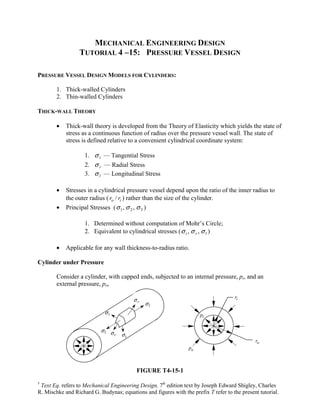
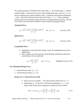


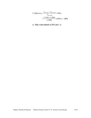

This document provides a tutorial on pressure vessel design, focusing on thick-walled and thin-walled cylinders' stress analysis under internal and external pressures. It discusses relevant stress theories, the relationship between geometry and stress, and methodologies for calculating stress states, including practical examples. The tutorial emphasizes the conditions under which thick-wall and thin-wall theories are applicable, demonstrating mathematical components to compute principal stresses and maximum shear stresses.


![ME 312 Mechanical Machine Design [Screws, Bolts, Nuts]](https://cdn.slidesharecdn.com/ss_thumbnails/me312-dsulec10-screws-170213050612-thumbnail.jpg?width=640&height=640&fit=bounds)


