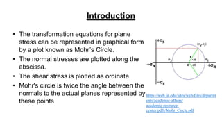
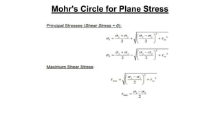
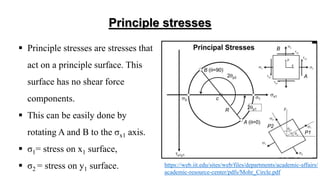
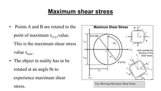
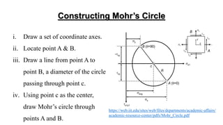
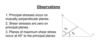
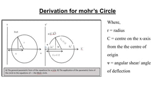
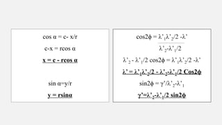
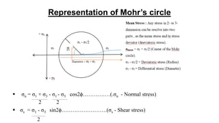
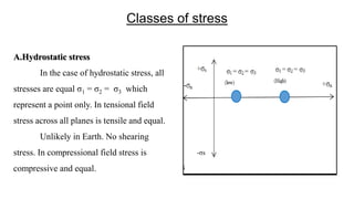
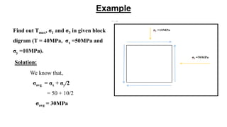
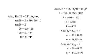
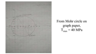
DR. HARISINGH GOUR VISHWAVIDYALAYA
(A CENTRAL UNIVERSITY)
SAGAR, (M.P.) - 470003
DEPARTMENT OF APPLIED GEOLOGY
PRESENTATION
ON
APPLICATIONS OF
MOHR’S CIRCLE
SUB. CODE. GEO SE-131
PRESENTED BY
Mr. MOHIT B. SHIVANE
Reg.No. Y21251027
M.Tech -1st SEM
Batch:- 2021-2022
Contents
SR.NO. TOPICS
01 Introduction
02 Mohr circle for plane stress
03 Principle stresses
04 Maximum shear stress
05 Constructing mohr circle
06 Observations
07 Derivation
08 Representation
09 Classes of stress
10 Other applications
11 Example
12 Conclusion
13 Reference
Introduction
• The transformation equations for plane
stress can be represented in graphical form
by a plot known as Mohr’s Circle.
• The normal stresses are plotted along the
abscissa.
• The shear stress is plotted as ordinate.
• Mohr's circle is twice the angle between the
normals to the actual planes represented by
these points
https://web.iit.edu/sites/web/files/departm
ents/academic-affairs/
academic-resource-
center/pdfs/Mohr_Circle.pdf
Mohr's Circle for Plane Stress
Principle stresses
 Principle stresses are stresses that
act on a principle surface. This
surface has no shear force
components.
 This can be easily done by
rotating A and B to the σx1 axis.
 σ1= stress on x1 surface,
 σ2 = stress on y1 surface. https://web.iit.edu/sites/web/files/departments/academic-affairs/
academic-resource-center/pdfs/Mohr_Circle.pdf
Maximum shear stress
• Points A and B are rotated to the
point of maximum τx1y1value.
This is the maximum shear stress
value τmax.
• The object in reality has to be
rotated at an angle θs to
experience maximum shear
stress.
Fig: Showing Maximum Shear Strain
Constructing Mohr’s Circle
i. Draw a set of coordinate axes.
ii. Locate point A & B.
iii. Draw a line from point A to
point B, a diameter of the circle
passing through point c.
iv. Using point c as the center,
draw Mohr’s circle through
points A and B.
https://web.iit.edu/sites/web/files/departments/academic-affairs/
academic-resource-center/pdfs/Mohr_Circle.pdf
Observations
1. Principal stresses occur on
mutually perpendicular planes.
2. Shear stresses are zero on
principal planes.
3. Planes of maximum shear stress
occur at 45° to the principal planes
σS
σn
Derivation for mohr’s Circle
Where,
r = radius
C = centre on the x-axis
from the the centre of
origin
ᴪ = angular shear/ angle
of deflection
cos α = c- x/r
c-x = rcos α
x = c - rcos α
sin α=y/r
y = rsinα
cos2ϕ = λ’1λ’2/2 -λ’
λ’2-λ’1/2
λ’2 - λ’1/2 cos2ϕ = λ’1λ’2/2 -λ’
λ’ = λ’1λ’2/2 - λ’2-λ’1/2 Cos2ϕ
sin2ϕ = γ’/λ’2-λ’1
γ’=λ’2-λ’1/2 sin2ϕ
Representation of Mohr’s circle
 σn = σ1 + σ3 - σ1 - σ3 cos2ϕ……………(.σn - Normal stress)
2 2
 σs = σ1 - σ3 sin2ϕ…………………….(σs - Shear stress)
2
Classes of stress
A.Hydrostatic stress
In the case of hydrostatic stress, all
stresses are equal σ1 = σ2 = σ3 which
represent a point only. In tensional field
stress across all planes is tensile and equal.
Unlikely in Earth. No shearing
stress. In compressional field stress is
compressive and equal.
-σs
B. Uniaxial stress
In this case two stresses are equal
and other is different. Only one
principal stress is non-zero tensile
or compressive.
C.Axial Stress
In this case, σ1 > σ2 = σ3
(axial compreession -prolate).
σ2 = σ3 > σ1 (axial extension-
oblate)
D. Triaxial Stress
Three principal stresses are
non-zero and σ1 = σ2 = σ3
Other Applications of Mohr Circle
It can be help to :-
i.Construct Mohr's circle with different values of σx, σy, and τxy.
ii.Locate σ1, σ2, and τmax on Mohr's circle.
iii.Calculate principal stresses and maximum shear stress.
iv.Calculate the orientation of principal planes and maximum shear stress plane.
v.Analyze the changes on a real stress element as its angle changes dynamically.
Example
Find out Tmax, σ1 and σ3 in given block
digram (T = 40MPa, σx =50MPa and
σy =10MPa).
Solution:
We know that,
σavg = σx + σy/2
= 50 + 10/2
σavg = 30MPa
Again, R = √ (σx - σy/2)2 + (Txy)2
R = √50 - 10 /2)2 + (40)2
R = √400 + 1600
R = √2000
R = 44.72
Now, σ1 = σavg + R
σ1 = 30 + 44.72
σ1 = 74.72MPa
Also, σ3 = σavg - R
σ3 = 30 - 44.72
σ3 = - 14.72 MPa
Also, Tan2θ = 2Txy/σx - σy
tan2θ = 2 x 40 / 50 -10
tan2θ = 2
2θ = tan-1(2)
2θ = 63.43o
θ = 31.71o
From Mohr circle on
graph paper,
Tmax = 40 MPa
CONCLUSION
When working with stress distributions, it must be pointed out that only one
state of stress is intrinsically unique, regardless of the orientation of the coordinates
system used to represent that state of stress. Therefore, when we have two elements at
the same point in a body with different orientations, the stresses acting on the faces of
the two elements are different, but they still represent the same state of stress.
This document explains how to draw the circle of stress or Mohr’s circle of
stress. The method has been shown with a worked example done step by step. The
obtained results have been checked considering the principal stresses equation.
REFERENCE
 Ramsay John G. and Huber Martin I.,2003. The Techniques Of Modern Structural
Geology (Volume 1 : Strain Analysis). 92-96.
 Jain A. K. Textbook of Structural Geology. 80-90.
 https://elearning.cpp.edu/learning-objects/mohrs-circle/
 https://web.iit.edu/sites/web/files/departments/academic-affairs/academic-resource-
center/pdfs/Mohr_Circle.pdf
Applications Of Mohr's Circle

Applications Of Mohr's Circle

  • 1.
    DR. HARISINGH GOURVISHWAVIDYALAYA (A CENTRAL UNIVERSITY) SAGAR, (M.P.) - 470003 DEPARTMENT OF APPLIED GEOLOGY PRESENTATION ON APPLICATIONS OF MOHR’S CIRCLE SUB. CODE. GEO SE-131 PRESENTED BY Mr. MOHIT B. SHIVANE Reg.No. Y21251027 M.Tech -1st SEM Batch:- 2021-2022
  • 2.
    Contents SR.NO. TOPICS 01 Introduction 02Mohr circle for plane stress 03 Principle stresses 04 Maximum shear stress 05 Constructing mohr circle 06 Observations 07 Derivation 08 Representation 09 Classes of stress 10 Other applications 11 Example 12 Conclusion 13 Reference
  • 3.
    Introduction • The transformationequations for plane stress can be represented in graphical form by a plot known as Mohr’s Circle. • The normal stresses are plotted along the abscissa. • The shear stress is plotted as ordinate. • Mohr's circle is twice the angle between the normals to the actual planes represented by these points https://web.iit.edu/sites/web/files/departm ents/academic-affairs/ academic-resource- center/pdfs/Mohr_Circle.pdf
  • 4.
    Mohr's Circle forPlane Stress
  • 5.
    Principle stresses  Principlestresses are stresses that act on a principle surface. This surface has no shear force components.  This can be easily done by rotating A and B to the σx1 axis.  σ1= stress on x1 surface,  σ2 = stress on y1 surface. https://web.iit.edu/sites/web/files/departments/academic-affairs/ academic-resource-center/pdfs/Mohr_Circle.pdf
  • 6.
    Maximum shear stress •Points A and B are rotated to the point of maximum τx1y1value. This is the maximum shear stress value τmax. • The object in reality has to be rotated at an angle θs to experience maximum shear stress. Fig: Showing Maximum Shear Strain
  • 7.
    Constructing Mohr’s Circle i.Draw a set of coordinate axes. ii. Locate point A & B. iii. Draw a line from point A to point B, a diameter of the circle passing through point c. iv. Using point c as the center, draw Mohr’s circle through points A and B. https://web.iit.edu/sites/web/files/departments/academic-affairs/ academic-resource-center/pdfs/Mohr_Circle.pdf
  • 8.
    Observations 1. Principal stressesoccur on mutually perpendicular planes. 2. Shear stresses are zero on principal planes. 3. Planes of maximum shear stress occur at 45° to the principal planes σS σn
  • 9.
    Derivation for mohr’sCircle Where, r = radius C = centre on the x-axis from the the centre of origin ᴪ = angular shear/ angle of deflection
  • 10.
    cos α =c- x/r c-x = rcos α x = c - rcos α sin α=y/r y = rsinα cos2ϕ = λ’1λ’2/2 -λ’ λ’2-λ’1/2 λ’2 - λ’1/2 cos2ϕ = λ’1λ’2/2 -λ’ λ’ = λ’1λ’2/2 - λ’2-λ’1/2 Cos2ϕ sin2ϕ = γ’/λ’2-λ’1 γ’=λ’2-λ’1/2 sin2ϕ
  • 11.
    Representation of Mohr’scircle  σn = σ1 + σ3 - σ1 - σ3 cos2ϕ……………(.σn - Normal stress) 2 2  σs = σ1 - σ3 sin2ϕ…………………….(σs - Shear stress) 2
  • 12.
    Classes of stress A.Hydrostaticstress In the case of hydrostatic stress, all stresses are equal σ1 = σ2 = σ3 which represent a point only. In tensional field stress across all planes is tensile and equal. Unlikely in Earth. No shearing stress. In compressional field stress is compressive and equal. -σs
  • 13.
    B. Uniaxial stress Inthis case two stresses are equal and other is different. Only one principal stress is non-zero tensile or compressive.
  • 14.
    C.Axial Stress In thiscase, σ1 > σ2 = σ3 (axial compreession -prolate). σ2 = σ3 > σ1 (axial extension- oblate)
  • 15.
    D. Triaxial Stress Threeprincipal stresses are non-zero and σ1 = σ2 = σ3
  • 16.
    Other Applications ofMohr Circle It can be help to :- i.Construct Mohr's circle with different values of σx, σy, and τxy. ii.Locate σ1, σ2, and τmax on Mohr's circle. iii.Calculate principal stresses and maximum shear stress. iv.Calculate the orientation of principal planes and maximum shear stress plane. v.Analyze the changes on a real stress element as its angle changes dynamically.
  • 17.
    Example Find out Tmax,σ1 and σ3 in given block digram (T = 40MPa, σx =50MPa and σy =10MPa). Solution: We know that, σavg = σx + σy/2 = 50 + 10/2 σavg = 30MPa
  • 18.
    Again, R =√ (σx - σy/2)2 + (Txy)2 R = √50 - 10 /2)2 + (40)2 R = √400 + 1600 R = √2000 R = 44.72 Now, σ1 = σavg + R σ1 = 30 + 44.72 σ1 = 74.72MPa Also, σ3 = σavg - R σ3 = 30 - 44.72 σ3 = - 14.72 MPa Also, Tan2θ = 2Txy/σx - σy tan2θ = 2 x 40 / 50 -10 tan2θ = 2 2θ = tan-1(2) 2θ = 63.43o θ = 31.71o
  • 19.
    From Mohr circleon graph paper, Tmax = 40 MPa
  • 20.
    CONCLUSION When working withstress distributions, it must be pointed out that only one state of stress is intrinsically unique, regardless of the orientation of the coordinates system used to represent that state of stress. Therefore, when we have two elements at the same point in a body with different orientations, the stresses acting on the faces of the two elements are different, but they still represent the same state of stress. This document explains how to draw the circle of stress or Mohr’s circle of stress. The method has been shown with a worked example done step by step. The obtained results have been checked considering the principal stresses equation.
  • 21.
    REFERENCE  Ramsay JohnG. and Huber Martin I.,2003. The Techniques Of Modern Structural Geology (Volume 1 : Strain Analysis). 92-96.  Jain A. K. Textbook of Structural Geology. 80-90.  https://elearning.cpp.edu/learning-objects/mohrs-circle/  https://web.iit.edu/sites/web/files/departments/academic-affairs/academic-resource- center/pdfs/Mohr_Circle.pdf