SlideShare a Scribd company logo
THIN AND THICK CYLINDERS
They are,
In many engineering applications, cylinders are frequently
used for transporting or storing of liquids, gases or fluids.
Eg: Pipes, Boilers, storage tanks etc.
These cylinders are subjected to fluid pressures. When a
cylinder is subjected to a internal pressure, at any point on the
cylinder wall, three types of stresses are induced on three
mutually perpendicular planes.
INTRODUCTION:
2. Longitudinal Stress (σL ) – This stress is directed along the
length of the cylinder. This is also tensile in nature and tends
to increase the length.
3. Radial pressure ( pr ) – It is compressive in nature.
Its magnitude is equal to fluid pressure on the inside wall and
zero on the outer wall if it is open to atmosphere.
1. Hoop or Circumferential Stress (σC) – This is directed along the
tangent to the circumference and tensile in nature. Thus, there
will be increase in diameter.
σ C σ L
1. Hoop Stress (σC) 2. Longitudinal Stress (σL) 3. Radial Stress (pr)
Element on the cylinder
wall subjected to these
three stresses
σ C
σ C
σC
p
σ L
σ L
σ L
p p
pr
σ L
σ L
σ C
σ C
pr
pr
INTRODUCTION:
A cylinder or spherical shell is considered to be thin when the
metal thickness is small compared to internal diameter.
i. e., when the wall thickness, ‘t’ is equal to or less than
‘d/20’, where ‘d’ is the internal diameter of the cylinder or shell,
we consider the cylinder or shell to be thin, otherwise thick.
Magnitude of radial pressure is very small compared to
other two stresses in case of thin cylinders and hence neglected.
THIN CYLINDERS
Longitudinal
axis
Longitudinal stress
Circumferential stress
t
The stress acting along the circumference of the cylinder is called
circumferential stresses whereas the stress acting along the length of
the cylinder (i.e., in the longitudinal direction ) is known as
longitudinal stress
The bursting will take place if the force due to internal (fluid)
pressure (acting vertically upwards and downwards) is more than the
resisting force due to circumferential stress set up in the material.
p
σc σc
P - internal pressure (stress)
σc –circumferential stress
P - internal pressure (stress)
σc – circumferential stress
dL
σc
p
t
EVALUATION OF CIRCUMFERENTIAL or HOOP STRESS (σC):
Consider a thin cylinder closed at both ends and subjected to internal
pressure ‘p’ as shown in the figure.
Let d=Internal diameter, t = Thickness of the wall
L = Length of the cylinder.
p d
t
σc
σc
dl
t
p
d
To determine the Bursting force across the diameter:
Consider a small length ‘dl’ of the cylinder and an elementary
area ‘dA’ as shown in the figure.
r
p
p dθ
dl
dA
dF ×
×
×
=
×
=
dθ
dl
dFx ×
×
×
×
= θ
cos
2
d
p
dA
σc
σc
dl
t
p
d
dθ
θ
Force on the elementary area,
Horizontal component of this force
dθ
dl ×
×
×
=
2
d
p
dθ
dl
dFy ×
×
×
×
= θ
sin
2
d
p
Vertical component of this force
The horizontal components cancel out
when integrated over semi-circular
portion as there will be another equal
and opposite horizontal component on
the other side of the vertical axis.
sin
2
d
p
force
bursting
l
diametrica
Total
0
∫ ×
×
×
×
=
∴
π
θ dθ
dl
dA
σc
σc
dl
t
p
θ
d
dθ
[ ]
surface.
curved
the
of
area
projected
p
d
p
cos
dl
2
d
p 0
×
=
×
×
=
−
×
×
×
= dl
π
θ
dl
c
c ×
×
×
=
∴ t
σ
2
)
σ
stress
ntial
circumfere
to
(due
force
Resisting
dl
dl ×
×
=
×
×
× d
p
t
σ
2
i.e., c
)
1
....(
..........
..........
t
2
d
p
σ
stress,
ntial
Circumfere c
×
×
=
∴
dL
σc
p
t
force
Bursting
force
Resisting
um,
equillibri
Under =
)
1
....(
..........
..........
t
2
d
p
σ
stress,
ntial
Circumfere c
×
×
=
∴
Force due to fluid pressure = p × area on which p is acting = p ×(d ×L)
(bursting force)
Force due to circumferential stress = σc × area on which σc is acting
(resisting force) = σc × ( L × t + L ×t ) = σc × 2 L × t
Under equilibrium bursting force = resisting force
p ×(d ×L) = σc × 2 L × t
Assumed as rectangular
LONGITUDINAL STRESS (σL):
p
σL
The force, due to pressure of the fluid, acting at the ends of the
thin cylinder, tends to burst the cylinder as shown in figure
P
A
B
The bursting of the cylinder takes
place along the section AB
EVALUATION OF LONGITUDINAL STRESS (σL):
d
4
π
p
cylinder)
of
end
(on the
force
bursting
al
Longitudin 2
×
×
=
p
t
σL
t
d
π
σ
force
Resisting L ×
×
×
=
∴
t
d
π
force
this
resisting
section
cross
of
Area ×
×
=
cylinder.
the
of
material
the
of
stress
al
Longitudin
σ
Let L =
t
d
π
σ
d
4
π
p
i.e., L
2
×
×
×
=
×
×
)
2
.........(
..........
t
4
d
p
σ
stress,
al
Longitudin L
×
×
=
∴
L
C σ
2
σ
(2),
&
(1)
eqs
From ×
=
force
resisting
force
bursting
um,
equillibri
Under =
t
d
π
σ
d
4
π
p
i.e.,
force
resisting
force
bursting
um,
equillibri
Under
L
2
×
×
×
=
×
×
=
)
2
.........(
..........
t
4
d
p
σ
stress,
al
Longitudin L
×
×
=
∴
t
d
π
σ
σ
σ
Re
d
4
π
p
acting
is
p
on which
area
pressure
fluid
to
due
Force
L
L
L
2
×
×
×
=
×
=
×
×
=
×
=
acting
is
which
on
area
force
sisting
p
circumference
EVALUATION OF STRAINS
A point on the surface of thin cylinder is subjected to biaxial
stress system, (Hoop stress and Longitudinal stress) mutually
perpendicular to each other, as shown in the figure. The strains due
to these stresses i.e., circumferential and longitudinal are obtained
by applying Hooke’s law and Poisson’s theory for elastic
materials.
σ C=(pd)/(2t)
σ C=(pd)/(2t)
σL=(pd)/(4t)
σ L=(pd)/(4t)
E
σ
μ
E
σ
ε
:
ε
strain,
ntial
Circumfere
L
C
C
C
×
−
=
)
3
..(
..........
..........
..........
μ)
2
(
E
t
4
d
p
d
δd
ε
i.e., C −
×
×
×
×
=
=
σ C=(pd)/(2
σC=(pd)/(2t)
σ L=(pd)/(4t)
σ L=(pd)/(4t)
Note: Let δd be the change in diameter. Then
( )
d
d
d
d
d
d
nce
circumfere
original
nce
circumfere
original
nce
circumfere
final
c
δ
π
π
δ
π
ε
=





 −
+
=
−
=
μ)
2
(
E
σ
E
σ
μ
E
σ
2
L
L
L
−
×
=
×
−
×
=
E
σ
μ
E
σ
ε
:
ε
strain,
al
Longitudin
C
L
L
L
×
−
=
)
4
..(
..........
..........
..........
μ)
2
1
(
E
t
4
d
p
L
δl
ε
i.e., L ×
−
×
×
×
×
=
=
V
v
STRAIN,
VOLUMETRIC
δ
Change in volume = δV = final volume – original volume
original volume = V = area of cylindrical shell × length
L
d
4
2
π
=
μ)
2
1
(
E
σ
E
)
σ
2
(
μ
E
σ L
L
L
×
−
×
=
×
×
−
=
final volume = final area of cross section × final length
[ ] [ ]
[ ] [ ]
[ ]
L
d
d
L
d
L
d
d
d
L
L
d
L
d
L
L
d
d
d
d
L
L
d
d
δ
δ
δ
δ
δ
δ
δ
π
δ
δ
δ
π
δ
δ
π
2
)
(
2
)
(
4
2
)
(
4
4
2
2
2
2
2
2
2
+
+
+
+
+
=
+
×
+
+
=
+
×
+
=
[ ]
L
d
d
d
L
L
d
volume
Final
L
d
d
and
L
d
L
d
as
such
quantities
smaller
the
neglecting
δ
δ
π
δ
δ
δ
δ
δ
2
2
2
2
2
4
2
)
(
,
)
(
+
+
=
[ ] [ ]
[ ]
L
d
d
d
L
V
L
d
L
d
d
d
L
L
d
V
volume
in
change
δ
δ
π
δ
π
δ
δ
π
δ
2
2
2
2
2
4
4
2
4
+
=
−
+
+
=
[ ]
L
d
4
π
2
4
π
V
dv
2
2
×
×
+
=
d
L
d
L
d δ
δ
= εL + 2 × εC
V
dV
)
5
.......(
..........
μ)
4
5
(
E
t
4
d
p
V
dv
i.e., ×
−
×
×
×
=
μ)
2
(
E
t
4
d
p
2
μ)
2
1
(
E
t
4
d
p
−
×
×
×
×
+
×
−
×
×
×
=
d
d
2
L
L δ
δ
×
+
=
2
4t
pd
2t
pd
2
σ
-
σ
τ
stress,
Shear
Maximum
other.
each
to
lar
perpendicu
act
and
normal
are
stresses
these
Both
al.
longitudin
and
ntial
Circumfere
viz.,
point,
any
at
stresses
principal
two
are
There
:
stress
Shear
Maximum
L
C
max
−
=
=
∴
)
5
.(
..........
..........
8t
pd
τ
i.e., max =
σ C=(pd)/(2t)
σC=(pd)/(2t)
σ L=(pd)/(4t)
σ L=(pd)/(4t)
2
4t
pd
2t
pd
2
σ
-
σ
τ
stress,
Shear
Maximum
:
stress
Shear
Maximum
L
C
max
−
=
=
∴
)
5
.(
..........
..........
8t
pd
τ
i.e., max =
PROBLEM 1:
A thin cylindrical shell is 3m long and 1m in internal diameter. It is
subjected to internal pressure of 1.2 MPa. If the thickness of the sheet is
12mm, find the circumferential stress, longitudinal stress, changes in
diameter, length and volume . Take E=200 GPa and μ= 0.3.
1. Circumferential stress, σC:
σC= (p×d) / (2×t)
= (1.2×1000) / (2× 12)
= 50 N/mm2
= 50 MPa (Tensile).
SOLUTION:
2. Longitudinal stress, σL:
σL = (p×d) / (4×t)
= σC/2 = 50/2
= 25 N/mm2
= 25 MPa (Tensile).
ILLUSTRATIVE PROBLEMS
3. Circumferential strain, εc:
Change in length = ε L ×L= 5×10-05
×3000 = 0.15 mm (Increase).
E
μ)
(2
t)
(4
d)
(p
εc
−
×
×
×
=
Change in diameter, δd = εc ×d
= 2.125×10-04
×1000 = 0.2125 mm (Increase).
E
μ)
2
(1
t)
(4
d)
(p
εL
×
−
×
×
×
=
4. Longitudinal strain, εL:
(Increase)
10
2.125
10
200
0.3)
(2
12)
(4
1000)
(1.2
04
-
3
×
=
×
−
×
×
×
=
(Increase)
10
5
10
200
0.3)
2
(1
12)
(4
1000)
(1.2
05
-
3
×
=
×
×
−
×
×
×
=
μ)
4
(5
E
t)
(4
d)
(p
V
dv
×
−
×
×
×
×
=
:
V
dv
strain,
Volumetric
V
10
4.75
dv
in volume,
Change -4
×
×
=
∴
(Increase)
10
4.75
)
3
.
0
4
5
(
10
200
)
12
4
(
)
1000
2
.
1
(
4
-
3
×
=
×
−
×
×
×
×
×
=
.
Litres
11919
.
1
m
10
1.11919
mm
10
1.11919
3000
1000
4
π
10
4.75
3
3
-
3
6
2
4
-
=
×
=
×
=
×
×
×
×
=
A copper tube having 45mm internal diameter and 1.5mm wall
thickness is closed at its ends by plugs which are at 450mm apart. The
tube is subjected to internal pressure of 3 MPa and at the same time
pulled in axial direction with a force of 3 kN. Compute: i) the change
in length between the plugs ii) the change in internal diameter of the
tube. Take ECU = 100 GPa, and μCU = 0.3.
A] Due to Fluid pressure of 3 MPa:
Longitudinal stress, σL = (p×d) / (4×t)
= (3×45) / (4× 1.5) = 22.50 N/mm2
= 22.50 MPa.
SOLUTION:
Change in length, δL= εL × L = 9 × 10-5
×450 = +0.0405 mm (increase)
E
)
μ
2
1
(
t
4
d)
(p
ε
strain,
Long. L
×
−
×
×
×
=
5
3
10
9
10
100
)
3
.
0
2
1
(
5
.
22 −
×
=
×
×
−
×
=
Change in diameter, δd= εc × d = 3.825 × 10-4
×45
= + 0.0172 mm (increase)
B] Due to Pull of 3 kN (P=3kN):
Area of cross section of copper tube, Ac = π × d × t
= π × 45 × 1.5 = 212.06 mm2
Longitudinal strain, ε L = direct stress/E = σ/E = P/(Ac × E)
= 3 × 10³
/(212.06 × 100 × 103
)
= 1.415 × 10⁻⁴
Change in length, δL=εL× L= 1.415 × 10-4
×450= +0.0637mm (increase)
E
)
μ
2
(
t)
(4
d)
(p
ε
strain
ntial
Circumfere C
−
×
×
×
=
Pd/4t = 22.5
4
3
10
825
.
3
10
100
)
3
.
0
2
(
5
.
22 −
×
=
×
−
×
=
Lateral strain, εlat= -μ × Longitudinal strain = -μ × εL
= - 0.3× 1.415 × 10-4
= -4.245 × 10⁻⁵
Change in diameter, δd = εlat × d = -4.245 × 10-5
×45
= - 1.91 × 10⁻³
mm (decrease)
C) Changes due to combined effects:
Change in length = 0.0405 + 0.0637 = + 0.1042 mm (increase)
Change in diameter = 0.01721 - 1.91 × 10-3
= + 0.0153 mm (increase)
PROBLEM 3:
A cylindrical boiler is 800mm in diameter and 1m length. It is
required to withstand a pressure of 100m of water. If the permissible
tensile stress is 20N/mm2
, permissible shear stress is 8N/mm2
and
permissible change in diameter is 0.2mm, find the minimum thickness
of the metal required. Take E = 200GPa, and μ = 0.3.
Fluid pressure, p = 100m of water = 100×9.81×103
N/m2
= 0.981N/mm2
.
SOLUTION:
1. Thickness from Hoop Stress consideration: (Hoop stress is critical
than long. Stress)
σC = (p×d)/(2×t)
20 = (0.981×800)/(2×t)
t = 19.62 mm
2. Thickness from Shear Stress consideration:
3. Thickness from permissible change in diameter consideration
(δd=0.2mm):
E
μ)
(2
t)
(4
d)
(p
d
δd −
×
×
×
=
Therefore, required thickness, t = 19.62 mm.
t)
(8
d)
(p
τmax
×
×
=
12.26mm.
t
t)
(8
800)
(0.981
8
=
∴
×
×
=
6.67mm
t
10
200
)
3
.
0
2
(
)
t
4
(
)
800
981
.
0
(
800
2
.
0
3
=
×
−
×
×
×
=
PROBLEM 4:
A cylindrical boiler has 450mm in internal diameter, 12mm thick and
0.9m long. It is initially filled with water at atmospheric pressure.
Determine the pressure at which an additional water of 0.187 liters
may be pumped into the cylinder by considering water to be
incompressible. Take E = 200 GPa, and μ = 0.3.
Additional volume of water, δV = 0.187 liters = 0.187×10⁻³
m3
= 187×103
mm3
SOLUTION:
3
6
3
2
mm
10
143.14
)
10
9
.
0
(
450
4
π
V ×
=
×
×
×
=
μ)
4
5
(
E
t
4
d
p
V
dV
×
−
×
×
×
=
Solving, p=7.33 N/mm2
)
33
.
0
4
5
(
10
200
12
4
450
p
10
143.14
10
187
3
6
3
×
−
×
×
×
×
=
×
×
JOINT EFFICIENCY
Longitudinal
rivets
Circumferential
rivets
Steel plates of only particular lengths and width are available. Hence
whenever larger size cylinders (like boilers) are required, a number
of plates are to be connected. This is achieved by using riveting in
circumferential and longitudinal directions as shown in figure. Due
to the holes for rivets, the net area of cross section decreases and
hence the stresses increase.
JOINT EFFICIENCY
The cylindrical shells like boilers are having two types of joints
namely Longitudinal and Circumferential joints. Due to the holes for
rivets, the net area of cross section decreases and hence the stresses
increase. If the efficiencies of these joints are known, the stresses
can be calculated as follows.
Let η L= Efficiency of Longitudinal joint
and η C = Efficiency of Circumferential joint.
...(1)
..........
η
t
2
d
p
σ
L
C
×
×
×
=
Circumferential stress is given by,
...(2)
..........
η
t
4
d
p
σ
C
L
×
×
×
=
Note: In longitudinal joint, the circumferential stress is developed
and in circumferential joint, longitudinal stress is developed.
Longitudinal stress is given by,
Circumferential
rivets
Longitudinal
rivets
If A is the gross area and Aeff is the effective resisting area then,
Efficiency = Aeff/A
Bursting force = p L d
Resisting force = σc ×Aeff = σc ×ηL ×A = σc ×ηL ×2 t L
Where η L=Efficiency of Longitudinal joint
Bursting force = Resisting force
p L d = σc ×ηL × 2 t L
...(1)
..........
η
t
2
d
p
σ
L
C
×
×
×
=
If η c=Efficiency of circumferential joint
Efficiency = Aeff/A
Bursting force = (π d2
/4)p
Resisting force = σL ×A′eff =σL ×ηc ×A′ = σL ×ηc ×π d t
Where η L=Efficiency of circumferential joint
Bursting force = Resisting force
...(2)
..........
η
t
4
d
p
σ
C
L
×
×
×
=
A cylindrical tank of 750mm internal diameter, 12mm thickness and
1.5m length is completely filled with an oil of specific weight
7.85 kN/m3
at atmospheric pressure. If the efficiency of longitudinal
joints is 75% and that of circumferential joints is 45%, find the
pressure head of oil in the tank. Also calculate the change in volume.
Take permissible tensile stress of tank plate as 120 MPa and E = 200
GPa, and μ = 0.3.
Let p = max permissible pressure in the tank.
Then we have, σL= (p×d)/(4×t) η C
120 = (p×750)/(4×12) 0.45
p = 3.456 MPa.
SOLUTION:
Also, σ C= (p×d)/(2×t) η L
120 = (p×750)/(2×12) 0.75
p = 2.88 MPa.
Max permissible pressure in the tank, p = 2.88 MPa.
μ)
4
5
(
E)
t
(4
d)
(p
V
dv
Strain,
Vol. ×
−
×
×
×
×
=
litres.
0.567
m
10
0.567
.
mm
10
567
.
0
1500
750
4
π
10
8.55
V
10
8.55
dv
10
8.55
0.3)
4
-
(5
)
10
200
12
(4
750)
(2.88
3
3
-
3
6
2
4
-
4
-
4
-
3
=
×
=
×
=
×
×
×
×
=
×
×
=
×
=
×
×
×
×
×
×
=
A boiler shell is to be made of 15mm thick plate having a limiting
tensile stress of 120 N/mm2
. If the efficiencies of the longitudinal and
circumferential joints are 70% and 30% respectively determine;
i) The maximum permissible diameter of the shell for an
internal pressure of 2 N/mm2
.
(ii) Permissible intensity of internal pressure when the shell
diameter is 1.5m.
(i) To find the maximum permissible diameter of the shell for an
internal pressure of 2 N/mm2
:
SOLUTION:
η
t
2
d
p
σ
e.,
i.
L
c
×
×
×
=
a) Let limiting tensile stress = Circumferential stress = σ c =
120N/mm2
.
d = 1260 mm
7
.
0
5
1
2
d
2
120
×
×
×
=
η
t
4
d
p
σ
e.,
i.
C
L
×
×
×
=
b) Let limiting tensile stress = Longitudinal stress = σ L = 120N/mm2
.
The maximum diameter of the cylinder in order to satisfy both the
conditions = 1080 mm.
d = 1080 mm
.
3
.
0
5
1
4
d
2
120
×
×
×
=
The maximum permissible pressure = 1.44 N/mm2
.
(ii) To find the permissible pressure for an internal diameter of 1.5m:
(d=1.5m=1500mm)
a) Let limiting tensile stress = Circumferential stress = σ c =
120N/mm2
.
η
t
2
d
p
σ
e.,
i.
L
c
×
×
×
=
b) Let limiting tensile stress = Longitudinal stress = σ L = 120N/mm2
.
η
t
4
d
p
σ
e.,
i.
C
L
×
×
×
=
.
N/mm
1.68
p
7
.
0
5
1
2
500
1
p
120
2
=
×
×
×
=
.
N/mm
1.44
p
3
.
0
5
1
4
500
1
p
120
2
=
×
×
×
=
PROBLEM 1:
Calculate the circumferential and longitudinal strains for a boiler of
1000mm diameter when it is subjected to an internal pressure of
1MPa. The wall thickness is such that the safe maximum tensile stress
in the boiler material is 35 MPa. Take E=200GPa and μ= 0.25.
(Ans: ε C=0.0001531, ε L=0.00004375)
PROBLEM 2:
A water main 1m in diameter contains water at a pressure head of
120m. Find the thickness of the metal if the working stress in the pipe
metal is 30 MPa. Take unit weight of water = 10 kN/m3
.
(Ans: t=20mm)
PROBLEMS FOR PRACTICE
THIN AND THICK
CYLINDERS -33
PROBLEM 3:
A gravity main 2m in diameter and 15mm in thickness. It is subjected
to an internal fluid pressure of 1.5 MPa. Calculate the hoop and
longitudinal stresses induced in the pipe material. If a factor of safety
4 was used in the design, what is the ultimate tensile stress in the pipe
material?
(Ans: σC=100 MPa, σL=50 MPa, σU=400 MPa)
PROBLEM 4:
At a point in a thin cylinder subjected to internal fluid pressure, the
value of hoop strain is 600×10-4
(tensile). Compute hoop and
longitudinal stresses. How much is the percentage change in the
volume of the cylinder? Take E=200GPa and μ= 0.2857.
(Ans: σC=140 MPa, σL=70 MPa, %age change=0.135%.)
THIN AND THICK
CYLINDERS -34
PROBLEM 5:
A cylindrical tank of 750mm internal diameter and 1.5m long is to be
filled with an oil of specific weight 7.85 kN/m3 under a pressure head
of 365 m. If the longitudinal joint efficiency is 75% and
circumferential joint efficiency is 40%, find the thickness of the tank
required. Also calculate the error of calculation in the quantity of oil
in the tank if the volumetric strain of the tank is neglected. Take
permissible tensile stress as 120 MPa, E=200GPa and μ= 0.3 for the
tank material. (Ans: t=12 mm, error=0.085%.)
THICK CYLINDERS
INTRODUCTION:
The thickness of the cylinder is large compared to that of thin
cylinder.
i. e., in case of thick cylinders, the metal thickness ‘t’ is more
than ‘d/20’, where ‘d’ is the internal diameter of the cylinder.
Magnitude of radial stress (pr) is large and hence it cannot be
neglected. The circumferential stress is also not uniform across the
cylinder wall. The radial stress is compressive in nature and
circumferential and longitudinal stresses are tensile in nature.
Radial stress and circumferential stresses are computed by using
‘Lame’s equations’.
LAME’S EQUATIONS (Theory) :
4. The material is homogeneous, isotropic and obeys Hooke’s law. (The
stresses are within proportionality limit).
1. Plane sections of the cylinder normal to its axis remain plane and
normal even under pressure.
2. Longitudinal stress (σL) and longitudinal strain (εL) remain constant
throughout the thickness of the wall.
3. Since longitudinal stress (σL) and longitudinal strain (εL) are constant,
it follows that the difference in the magnitude of hoop stress and
radial stress (pr) at any point on the cylinder wall is a constant.
ASSUMPTIONS:
LAME’S EQUATIONS FOR RADIAL PRESSURE AND
CIRCUMFERENTIAL STRESS
Consider a thick cylinder of external radius r1 and internal radius
r2, containing a fluid under pressure ‘p’ as shown in the fig.
Let ‘L’ be the length of the cylinder.
p
r2
r1
p
Consider an elemental ring of radius ‘r’ and thickness ‘δr’ as shown
in the above figures. Let pr and (pr+ δpr) be the intensities of radial
pressures at inner and outer faces of the ring.
pr
pr+δpr
r2
r1
r
pr
pr+δpr
r2
r1
r
σc σc
r δr
Pr
pr+δpr
External
pressure
Consider the longitudinal
section XX of the ring as
shown in the fig.
The bursting force is
evaluated by considering
the projected area,
‘2×r×L’ for the inner face
and ‘2×(r+δr)×L’ for the
outer face .
The net bursting force, P = pr×2×r×L - (pr+δpr)×2×(r+δr)×L
=( -pr× δr - r×δpr - δpr × δr) 2L
Bursting force is resisted by the hoop tensile force developing at the
level of the strip i.e.,
Fr=σc×2 ×δr×L
L
r
pr
pr+δpr
r+δr
X X
Thus, for equilibrium, P = Fr
(-pr× δr - r×δpr- δpr × δr) 2L = σ c×2×δr×L
-pr× δr - r×δpr- δpr × δr = σ c×δr
Neglecting products of small quantities, (i.e., δpr × δr)
σ c = - pr – (r× δpr )/ δr ...…………….(1)
Longitudinal strain is constant. Hence we have,
since σL, E and μ are constants (σc – Pr) should be constant . Let it be
equal to 2a. Thus
constant
E
p
μ
E
σ
μ
E
σ r
C
L
=
×
+
×
− Since Pr is compressive
ε L =
constant
)
p
σ
(
μ
E
σ
r
C
L
=
−
−
E
ε L =
σ c- pr = 2a,
i.e., σc = pr + 2a, ………………(2)
From (1), pr+ 2a = - pr – (r× δpr ) / δr
r
r
r
p
-
a)
p
(
2
δ
δ
×
=
+ r
)
3
.(
..........
a)
p
(
p
2
r
r
r
+
=
×
−
δ
δ
r
i. e.,
Integrating, (-2 ×loge r) + c = loge (pr + a)
Where c is constant of integration. Let it be taken as loge b, where
‘b’ is another constant.
Thus, loge (pr+a) = -2 ×loge r + loge b = - loge r2
+ loge b = loge
2
r
b
.....(4)
..........
a
r
b
p
stress,
radial
or,
r
b
a
p
i.e., 2
r
2
r −
=
=
+
The equations (4) & (5) are known as “Lame’s Equations” for radial
pressure and hoop stress at any specified point on the cylinder wall.
Thus, r1≤r ≤r2.
a
2
a
b
a
2
p
σ
stress,
Hoop 2
r
c +
−
=
+
=
r
.......(5)
..........
..........
a
r
b
σ
i.e., 2
c +
=
Substituting it in equation 2, we get
ANALYSIS FOR LONGITUDINAL STRESS
Consider a transverse section near the end wall as shown in the fig.
Bursting force, P =π×r2
2
×p
Resisting force is due to longitudinal stress ‘σ L’.
i.e., FL= σ L× π ×(r1
2
-r2
2
)
For equilibrium, FL= P
σ L× π ×(r1
2
-r2
2
)= π ×r2
2
×p
Therefore, longitudinal stress,
(Tensile)
)
r
(r
r
p
σ 2
2
2
1
2
2
L
−
×
=
p
p
r2
r1
σL
σ L
σL
σL
L
NOTE:
1. Variations of Hoop stress and Radial stress are parabolic across
the cylinder wall.
2. At the inner edge, the stresses are maximum.
3. The value of ‘Permissible or Maximum Hoop Stress’ is to be
considered on the inner edge.
4. The maximum shear stress (σ max) and Hoop, Longitudinal and
radial strains (εc, εL, εr) are calculated as in thin cylinder but
separately for inner and outer edges.
ILLUSTRATIVE PROBLEMS
PROBLEM 1:
A thick cylindrical pipe of external diameter 300mm and internal
diameter 200mm is subjected to an internal fluid pressure of 20N/mm2
and external pressure of 5 N/mm2
. Determine the maximum hoop
stress developed and draw the variation of hoop stress and radial
stress across the thickness. Show at least four points for each case.
SOLUTION:
External diameter = 300mm. External radius, r1=150mm.
Internal diameter = 200mm. Internal radius, r2=100mm.
Lame’s equations:
For Hoop stress, .........(1)
For radial stress, .........(2)
a
r
b
σ 2
c +
=
a
r
b
p 2
r −
=
Boundary conditions:
At r =100mm (on the inner face), radial pressure = 20N/mm2
i.e.,
Similarly, at r =150mm (on the outer face), radial pressure = 5N/mm2
i.e.,
)
........(3
..........
a
100
b
20 2
−
=
)
........(4
..........
a
150
b
5 2
−
=
..(5)
..........
7
r
2,70,000
σ 2
c +
=
..(6)
..........
7
r
2,70,000
p 2
r −
=
Solving equations (3) & (4), we get a = 7, b = 2,70,000.
Lame’s equations are, for Hoop stress,
For radial stress,
To draw variations of Hoop stress & Radial stress :
At r =100mm (on the inner face),
(Comp)
MPa
20
7
100
2,70,000
p
stress,
Radial
(Tensile)
MPa
34
7
100
2,70,000
σ
stress,
Hoop
2
r
2
c
=
−
=
=
+
=
At r =120mm,
(Comp)
MPa
11.75
7
120
2,70,000
p
stress,
Radial
(Tensile)
MPa
25.75
7
120
2,70,000
σ
stress,
Hoop
2
r
2
c
=
−
=
=
+
=
At r =135mm,
(Comp)
MPa
7.81
7
135
2,70,000
p
stress,
Radial
(Tensile)
MPa
21.81
7
135
2,70,000
σ
stress,
Hoop
2
r
2
c
=
−
=
=
+
=
(Comp)
MPa
5
7
150
2,70,000
p
stress,
Radial
(Tensile)
MPa
19
7
150
2,70,000
σ
stress,
Hoop
150mm,
r
At
2
r
2
c
=
−
=
=
+
=
=
Variation of Hoop stress & Radial stress
Variation of Hoop
Stress-Tensile
(Parabolic)
Variation of Radial
Stress –Comp
(Parabolic)
PROBLEM 2:
Find the thickness of the metal required for a thick cylindrical shell of
internal diameter 160mm to withstand an internal pressure of 8 N/mm2
.
The maximum hoop stress in the section is not to exceed 35 N/mm2
.
SOLUTION:
Internal radius, r2=80mm.
......(2)
..........
a
r
b
p
stress,
Radial
for
(1)
..........
..........
a
r
b
σ
Stress,
Hoop
for
are,
equations
s
Lame'
2
r
2
c
−
=
+
=
face)
inner
on
max
is
stress
Hoop
(
.
N/mm
35
σ
stress,
Hoop
and
,
N/mm
8
p
stress
radial
80mm,
r
at
are,
conditions
Boundary
2
C
2
r

=
=
=
,600.
37
,
1
b
13.5,
a
get
we
(4),
&
(3)
equations
Solving =
=
)
........(4
..........
a
0
8
b
35
)
........(3
..........
a
0
8
b
8
i.e.,
2
2
+
=
−
=
..(6)
..........
5
.
13
r
1,37,600
p
and
..(5)
..........
5
.
13
r
1,37,600
σ
are,
equations
s
Lame'
2
r
2
c
−
=
+
=
∴
.
r
r
at
0
p
i.e.,
0.
pressure
face,
outer
On the
1
r =
=
=
20.96mm.
r
-
r
metal
the
of
Thickness 2
1
=
=
∴
100.96mm.
r
5
.
13
r
1,37,600
0
1
2
1
=
∴
−
=
∴
PROBLEM 3:
A thick cylindrical pipe of outside diameter 300mm and internal
diameter 200mm is subjected to an internal fluid pressure of 14 N/mm2
.
Determine the maximum hoop stress developed in the cross section.
What is the percentage error if the maximum hoop stress is calculated
by the equations for thin cylinder?
SOLUTION:
Internal radius, r2=100mm. External radius, r1=150mm
.
Lame’s equations:
For Hoop stress, .........(1)
For radial pressure, .........(2)
a
r
b
σ 2
c +
=
a
r
b
p 2
r −
=
Boundary conditions:
At x =100mm Pr = 14N/mm2
i.e.,
Similarly, at x =150mm Pr = 0
i.e.,
)
........(1
..........
a
100
b
14 2
−
=
)
........(2
..........
a
150
b
0 2
−
=
..(3)
..........
2
.
11
r
22,500
σ
stress,
Hoop
for
equation
s
Lame' 2
r +
=
∴
Solving, equations (1) & (2), we get a =11.2, b = 2,52,000.
MPa.
36.4
2
.
11
100
252000
σ 2
max =
+
=
Max hoop stress on the inner face (where x=100mm):
.
23.08%
100
)
36.4
28
-
36.4
(
error
Percentage =
×
=
14MPa.
p
and
50mm
t
200mm,
D
e
wher
t
2
d
p
σ
formula,
cylinder
By thin max
=
=
=
×
×
=
MPa.
28
50
2
200
14
σmax =
×
×
=
∴
PROBLEM 4:
The principal stresses at the inner edge of a cylindrical shell are
81.88 MPa (T) and 40MPa (C). The internal diameter of the
cylinder is 180mm and the length is 1.5m. The longitudinal
stress is 21.93 MPa (T). Find,
(i) Max shear stress at the inner edge.
(ii) Change in internal diameter.
(iii)Change in length.
(iv) Change in volume.
Take E=200 GPa and μ=0.3.
SOLUTION:
2
(-40)
-
81.88
2
p
-
σ
τ
:
face
inner
on the
stress
shear
Max
i)
r
C
max =
=
= 60.94 MPa
σ
E
μ
-
p
E
μ
-
E
σ
d
δd
:
diameter
inner
in
Change
ii)
L
r
C
×
×
=
σ
E
μ
-
p
E
μ
-
E
σ
L
δl
:
Length
in
Change
iii)
C
r
L
×
×
=
0.078mm.
δd
10
4.365
)
40
(
10
200
0.3
-
93
.
1
2
10
200
0.3
-
10
200
81.88
4
-
3
3
3
+
=
∴
×
=
−
×
×
×
×
×
=
0.070mm.
δl
10
46.83
81.88
10
200
0.3
-
)
40
(
10
200
0.3
-
10
200
93
.
1
2
6
-
3
3
3
+
=
∴
×
=
×
×
−
×
×
×
=
D
δd
2
L
δl
V
δV
:
in volume
Change
iv)
×
+
=
.
mm
10
35.11
)
4
1500
180
π
(
10
9.198
δV
3
3
2
4
-
×
=
×
×
×
×
=
∴
= 9.198 ×10⁻⁴
PROBLEM 5:
Find the max internal pressure that can be allowed into a thick pipe of
outer diameter of 300mm and inner diameter of 200mm so that tensile
tress in the metal does not exceed 16 MPa if, (i) there is no external
luid pressure, (ii) there is a fluid pressure of 4.2 MPa.
SOLUTION:
External radius, r1=150mm.
Internal radius, r2=100mm.
Boundary conditions:
At r=100mm , σc = 16N/mm2
At r=150mm , Pr = 0
Case (i) – When there is no external fluid pressure:
)
........(2
..........
a
150
b
0
)
........(1
..........
a
100
b
16
i.e.,
2
2
−
=
+
=
Solving we get, a = 4.92 & b=110.77×10³
)
........(4
..........
92
.
4
10
110.77
p
)
........(3
..........
92
.
4
10
110.77
σ
that
so
2
3
r
2
3
c
−
×
=
+
×
=
r
r
MPa.
6.16
92
.
4
00
1
10
110.77
p
100mm,
r
where
face
inner
on the
pressure
Fluid
2
3
r =
−
×
=
=
Boundary conditions:
At r=100mm , σc= 16 N/mm2
At r=150mm , pr= 4.2 MPa.
Case (ii) – When there is an external fluid pressure of 4.2 MPa:
)
........(2
..........
a
150
b
4.2
)
........(1
..........
a
100
b
16
i.e.,
2
2
−
=
+
=
Solving we get, a = 2.01 & b=139.85×10³
)
........(4
..........
01
.
2
10
139.85
p
)
........(3
..........
01
.
2
10
139.85
σ
that
so
2
3
r
2
3
r
−
×
=
+
×
=
r
r
MPa.
11.975
01
.
2
00
1
10
139.85
p
100mm,
where
face
inner
on the
pressure
Fluid
2
3
r =
−
×
=
=
r
PROBLEM 1:
A pipe of 150mm internal diameter with the metal thickness of 50mm
transmits water under a pressure of 6 MPa. Calculate the maximum
and minimum intensities of circumferential stresses induced.
(Ans: 12.75 MPa, 6.75 MPa)
PROBLEM 2:
Determine maximum and minimum hoop stresses across the section
of a pipe of 400mm internal diameter and 100mm thick when a fluid
under a pressure of 8N/mm2
is admitted. Sketch also the radial
pressure and hoop stress distributions across the thickness.
(Ans: σmax=20.8 N/mm2
,σmin=12.8 N/mm2
)
PROBLEM 3:
A thick cylinder with external diameter 240mm and internal diameter
‘D’ is subjected to an external pressure of 50 MPa. Determine the
diameter ‘D’ if the maximum hoop stress in the cylinder is not to
exceed 200 MPa. (Ans: 169.7 mm)
PROBLEMS FOR PRACTICE
THIN AND THICK
CYLINDERS -63
PROBLEM 4:
A thick cylinder of 1m inside diameter and 7m long is subjected to an
internal fluid pressure of 40 MPa. Determine the thickness of the
cylinder if the maximum shear stress in the cylinder is not to exceed
65 MPa. What will be the increase in the volume of the cylinder?
E=200 GPa, μ=0.3. (Ans: t=306.2mm, δv=5.47×10⁻³
m3
)
PROBLEM 5:
A thick cylinder is subjected to both internal and external pressure.
The internal diameter of the cylinder is 150mm and the external
diameter is 200mm. If the maximum permissible stress in the
cylinder is 20 N/mm2
and external radial pressure is 4 N/mm2
,
determine the intensity of internal radial pressure. (Ans:
10.72 N/mm2
)
THIN AND THICK
CYLINDERS -64

More Related Content

What's hot

Governor
GovernorGovernor
Governor
R A Shah
 
Theory of machines solution ch 11
Theory of machines solution ch 11 Theory of machines solution ch 11
Theory of machines solution ch 11
Saif al-din ali
 
Stress Analysis & Pressure Vessels
Stress Analysis & Pressure VesselsStress Analysis & Pressure Vessels
Stress Analysis & Pressure Vessels
Hugo Méndez
 
Thick cylinders
Thick cylinders Thick cylinders
Thick cylinders
sushma chinta
 
mechanical vibration: force transmitted to the foundation
mechanical vibration: force transmitted to the foundationmechanical vibration: force transmitted to the foundation
mechanical vibration: force transmitted to the foundation
Jaya Teja
 
Strength of Materials
Strength of Materials Strength of Materials
Strength of Materials
Ravi Vishwakarma
 
Torsion Hollow Shaft
Torsion Hollow ShaftTorsion Hollow Shaft
Torsion Hollow Shaft
tejasp
 
IC engine Mathematical problem & solution
 IC engine Mathematical problem & solution IC engine Mathematical problem & solution
IC engine Mathematical problem & solution
Shahjalal University of Science and Techology
 
Unit 4 helical gear
Unit 4 helical gearUnit 4 helical gear
Unit 4 helical gear
Dr. L K Bhagi
 
Design of cotter joint (machine design & industrial drafting )
Design of cotter joint (machine design & industrial drafting )Design of cotter joint (machine design & industrial drafting )
Design of cotter joint (machine design & industrial drafting )
Digvijaysinh Gohil
 
Turboprop
TurbopropTurboprop
Turboprop
kivancgunendi
 
Unit1 designof levers
Unit1 designof leversUnit1 designof levers
Unit1 designof levers
Somnath Kolgiri
 
DESIGN OF IC ENGINE COMPONENT-CYLINDER
DESIGN OF IC ENGINE COMPONENT-CYLINDER DESIGN OF IC ENGINE COMPONENT-CYLINDER
DESIGN OF IC ENGINE COMPONENT-CYLINDER
Snehal Patel
 
Internal combustion engine components design
Internal combustion engine components designInternal combustion engine components design
Internal combustion engine components design
Kailash Bhosale
 
sliding and rolling contact bearings
sliding and rolling contact bearingssliding and rolling contact bearings
sliding and rolling contact bearings
Venkateswara Reddy Kolagotla
 
Chapter10 clutches and_brakes
Chapter10 clutches and_brakesChapter10 clutches and_brakes
Chapter10 clutches and_brakes
mirhadizadeh
 
Locomotive Coupler RDSO
Locomotive Coupler RDSOLocomotive Coupler RDSO
Locomotive Coupler RDSO
Faraz Khan
 
A report about marine diesel engines
A report about marine diesel enginesA report about marine diesel engines
A report about marine diesel engines
armanimams
 
Unit 2 Design Of Shafts Keys and Couplings
Unit 2 Design Of Shafts Keys and CouplingsUnit 2 Design Of Shafts Keys and Couplings
Unit 2 Design Of Shafts Keys and Couplings
Mahesh Shinde
 
U1 Design of cylinder
U1 Design of cylinderU1 Design of cylinder
U1 Design of cylinder
karuppusamy pitchai
 

What's hot (20)

Governor
GovernorGovernor
Governor
 
Theory of machines solution ch 11
Theory of machines solution ch 11 Theory of machines solution ch 11
Theory of machines solution ch 11
 
Stress Analysis & Pressure Vessels
Stress Analysis & Pressure VesselsStress Analysis & Pressure Vessels
Stress Analysis & Pressure Vessels
 
Thick cylinders
Thick cylinders Thick cylinders
Thick cylinders
 
mechanical vibration: force transmitted to the foundation
mechanical vibration: force transmitted to the foundationmechanical vibration: force transmitted to the foundation
mechanical vibration: force transmitted to the foundation
 
Strength of Materials
Strength of Materials Strength of Materials
Strength of Materials
 
Torsion Hollow Shaft
Torsion Hollow ShaftTorsion Hollow Shaft
Torsion Hollow Shaft
 
IC engine Mathematical problem & solution
 IC engine Mathematical problem & solution IC engine Mathematical problem & solution
IC engine Mathematical problem & solution
 
Unit 4 helical gear
Unit 4 helical gearUnit 4 helical gear
Unit 4 helical gear
 
Design of cotter joint (machine design & industrial drafting )
Design of cotter joint (machine design & industrial drafting )Design of cotter joint (machine design & industrial drafting )
Design of cotter joint (machine design & industrial drafting )
 
Turboprop
TurbopropTurboprop
Turboprop
 
Unit1 designof levers
Unit1 designof leversUnit1 designof levers
Unit1 designof levers
 
DESIGN OF IC ENGINE COMPONENT-CYLINDER
DESIGN OF IC ENGINE COMPONENT-CYLINDER DESIGN OF IC ENGINE COMPONENT-CYLINDER
DESIGN OF IC ENGINE COMPONENT-CYLINDER
 
Internal combustion engine components design
Internal combustion engine components designInternal combustion engine components design
Internal combustion engine components design
 
sliding and rolling contact bearings
sliding and rolling contact bearingssliding and rolling contact bearings
sliding and rolling contact bearings
 
Chapter10 clutches and_brakes
Chapter10 clutches and_brakesChapter10 clutches and_brakes
Chapter10 clutches and_brakes
 
Locomotive Coupler RDSO
Locomotive Coupler RDSOLocomotive Coupler RDSO
Locomotive Coupler RDSO
 
A report about marine diesel engines
A report about marine diesel enginesA report about marine diesel engines
A report about marine diesel engines
 
Unit 2 Design Of Shafts Keys and Couplings
Unit 2 Design Of Shafts Keys and CouplingsUnit 2 Design Of Shafts Keys and Couplings
Unit 2 Design Of Shafts Keys and Couplings
 
U1 Design of cylinder
U1 Design of cylinderU1 Design of cylinder
U1 Design of cylinder
 

Similar to thinandthickcylinders-180511185429.pdf

Thin and thick cylinders
Thin and thick cylindersThin and thick cylinders
Thin and thick cylinders
Shivendra Nandan
 
Thick and thin cylinders
Thick and thin cylindersThick and thin cylinders
Thick and thin cylinders
shashank sinnha
 
Thin cylinder
Thin cylinderThin cylinder
Thin cylinder
senthamarai kannan
 
Thin and thick cylinders
Thin and thick  cylindersThin and thick  cylinders
Thin and thick cylinders
nohita09123
 
Thin cylinders 1
Thin cylinders 1Thin cylinders 1
Thin cylinders 1
Sukhvinder Singh
 
Thin cylinder analysis under diff. stresses
Thin cylinder  analysis under diff. stressesThin cylinder  analysis under diff. stresses
Thin cylinder analysis under diff. stresses
KUNJAN PATEL
 
Thin cylinder ppt
Thin cylinder pptThin cylinder ppt
Thin cylinder ppt
Er Alfaj Shaikh
 
Thin Cylinders
Thin Cylinders Thin Cylinders
Thin Cylinders
Chandigarh University
 
thin walled vessel and thick wall cylinder(strength of the material)
thin walled vessel and thick wall cylinder(strength of the material)thin walled vessel and thick wall cylinder(strength of the material)
thin walled vessel and thick wall cylinder(strength of the material)
Ugeswran Thamalinggam
 
IARE_SOM_II_PPT.pdf
IARE_SOM_II_PPT.pdfIARE_SOM_II_PPT.pdf
IARE_SOM_II_PPT.pdf
PrashantKuwar
 
thickcylinders-160605084017.pdf
thickcylinders-160605084017.pdfthickcylinders-160605084017.pdf
thickcylinders-160605084017.pdf
SukantaMandal17
 
Members subjected to axisymmetric loads
Members subjected to axisymmetric loadsMembers subjected to axisymmetric loads
Members subjected to axisymmetric loads
Yatin Singh
 
DMM I Unit III Bolted Joints 25-05-2021.pptx
DMM I Unit III Bolted Joints 25-05-2021.pptxDMM I Unit III Bolted Joints 25-05-2021.pptx
DMM I Unit III Bolted Joints 25-05-2021.pptx
Venkateswarlu Velisala
 
L21 MOS OCT 2020.pptx .
L21 MOS OCT 2020.pptx                           .L21 MOS OCT 2020.pptx                           .
L21 MOS OCT 2020.pptx .
happycocoman
 
Ppt springs
Ppt springsPpt springs
Lectur of thin walled pressure vessels
Lectur of thin walled pressure vesselsLectur of thin walled pressure vessels
Lectur of thin walled pressure vessels
NarasimhaReddyP2
 
Solution manual 17 19
Solution manual 17 19Solution manual 17 19
Solution manual 17 19
Rafi Flydarkzz
 
4unit-200715014624 circular shaft - Copy.pptx
4unit-200715014624 circular shaft - Copy.pptx4unit-200715014624 circular shaft - Copy.pptx
4unit-200715014624 circular shaft - Copy.pptx
Praveen Kumar
 
Torsion
TorsionTorsion
Mechanics of solids ii by iffteker anam
Mechanics of solids ii by iffteker anamMechanics of solids ii by iffteker anam
Mechanics of solids ii by iffteker anam
ksovon31
 

Similar to thinandthickcylinders-180511185429.pdf (20)

Thin and thick cylinders
Thin and thick cylindersThin and thick cylinders
Thin and thick cylinders
 
Thick and thin cylinders
Thick and thin cylindersThick and thin cylinders
Thick and thin cylinders
 
Thin cylinder
Thin cylinderThin cylinder
Thin cylinder
 
Thin and thick cylinders
Thin and thick  cylindersThin and thick  cylinders
Thin and thick cylinders
 
Thin cylinders 1
Thin cylinders 1Thin cylinders 1
Thin cylinders 1
 
Thin cylinder analysis under diff. stresses
Thin cylinder  analysis under diff. stressesThin cylinder  analysis under diff. stresses
Thin cylinder analysis under diff. stresses
 
Thin cylinder ppt
Thin cylinder pptThin cylinder ppt
Thin cylinder ppt
 
Thin Cylinders
Thin Cylinders Thin Cylinders
Thin Cylinders
 
thin walled vessel and thick wall cylinder(strength of the material)
thin walled vessel and thick wall cylinder(strength of the material)thin walled vessel and thick wall cylinder(strength of the material)
thin walled vessel and thick wall cylinder(strength of the material)
 
IARE_SOM_II_PPT.pdf
IARE_SOM_II_PPT.pdfIARE_SOM_II_PPT.pdf
IARE_SOM_II_PPT.pdf
 
thickcylinders-160605084017.pdf
thickcylinders-160605084017.pdfthickcylinders-160605084017.pdf
thickcylinders-160605084017.pdf
 
Members subjected to axisymmetric loads
Members subjected to axisymmetric loadsMembers subjected to axisymmetric loads
Members subjected to axisymmetric loads
 
DMM I Unit III Bolted Joints 25-05-2021.pptx
DMM I Unit III Bolted Joints 25-05-2021.pptxDMM I Unit III Bolted Joints 25-05-2021.pptx
DMM I Unit III Bolted Joints 25-05-2021.pptx
 
L21 MOS OCT 2020.pptx .
L21 MOS OCT 2020.pptx                           .L21 MOS OCT 2020.pptx                           .
L21 MOS OCT 2020.pptx .
 
Ppt springs
Ppt springsPpt springs
Ppt springs
 
Lectur of thin walled pressure vessels
Lectur of thin walled pressure vesselsLectur of thin walled pressure vessels
Lectur of thin walled pressure vessels
 
Solution manual 17 19
Solution manual 17 19Solution manual 17 19
Solution manual 17 19
 
4unit-200715014624 circular shaft - Copy.pptx
4unit-200715014624 circular shaft - Copy.pptx4unit-200715014624 circular shaft - Copy.pptx
4unit-200715014624 circular shaft - Copy.pptx
 
Torsion
TorsionTorsion
Torsion
 
Mechanics of solids ii by iffteker anam
Mechanics of solids ii by iffteker anamMechanics of solids ii by iffteker anam
Mechanics of solids ii by iffteker anam
 

More from muralikrishna317515

4 - 3 Structural and Architectural Potential of Masonry.pdf
4 - 3 Structural and Architectural Potential of Masonry.pdf4 - 3 Structural and Architectural Potential of Masonry.pdf
4 - 3 Structural and Architectural Potential of Masonry.pdf
muralikrishna317515
 
2 - 1 Understanding Perception Conscious and Subconscious Mind and Meditation...
2 - 1 Understanding Perception Conscious and Subconscious Mind and Meditation...2 - 1 Understanding Perception Conscious and Subconscious Mind and Meditation...
2 - 1 Understanding Perception Conscious and Subconscious Mind and Meditation...
muralikrishna317515
 
Shashank B S_Charusat.pdf
Shashank B S_Charusat.pdfShashank B S_Charusat.pdf
Shashank B S_Charusat.pdf
muralikrishna317515
 
KNS_LRFD-GEOTECH_CHANGA_08-09-21-RKS.pdf
KNS_LRFD-GEOTECH_CHANGA_08-09-21-RKS.pdfKNS_LRFD-GEOTECH_CHANGA_08-09-21-RKS.pdf
KNS_LRFD-GEOTECH_CHANGA_08-09-21-RKS.pdf
muralikrishna317515
 
Deep Foundation Technologies for Resurgent India Charotar Basarkar Circulatio...
Deep Foundation Technologies for Resurgent India Charotar Basarkar Circulatio...Deep Foundation Technologies for Resurgent India Charotar Basarkar Circulatio...
Deep Foundation Technologies for Resurgent India Charotar Basarkar Circulatio...
muralikrishna317515
 
2 - 3 Soil Investigation Asha.pdf
2 - 3 Soil Investigation Asha.pdf2 - 3 Soil Investigation Asha.pdf
2 - 3 Soil Investigation Asha.pdf
muralikrishna317515
 

More from muralikrishna317515 (7)

4 - 3 Structural and Architectural Potential of Masonry.pdf
4 - 3 Structural and Architectural Potential of Masonry.pdf4 - 3 Structural and Architectural Potential of Masonry.pdf
4 - 3 Structural and Architectural Potential of Masonry.pdf
 
2 - 1 Understanding Perception Conscious and Subconscious Mind and Meditation...
2 - 1 Understanding Perception Conscious and Subconscious Mind and Meditation...2 - 1 Understanding Perception Conscious and Subconscious Mind and Meditation...
2 - 1 Understanding Perception Conscious and Subconscious Mind and Meditation...
 
Civil-flyer.pdf
Civil-flyer.pdfCivil-flyer.pdf
Civil-flyer.pdf
 
Shashank B S_Charusat.pdf
Shashank B S_Charusat.pdfShashank B S_Charusat.pdf
Shashank B S_Charusat.pdf
 
KNS_LRFD-GEOTECH_CHANGA_08-09-21-RKS.pdf
KNS_LRFD-GEOTECH_CHANGA_08-09-21-RKS.pdfKNS_LRFD-GEOTECH_CHANGA_08-09-21-RKS.pdf
KNS_LRFD-GEOTECH_CHANGA_08-09-21-RKS.pdf
 
Deep Foundation Technologies for Resurgent India Charotar Basarkar Circulatio...
Deep Foundation Technologies for Resurgent India Charotar Basarkar Circulatio...Deep Foundation Technologies for Resurgent India Charotar Basarkar Circulatio...
Deep Foundation Technologies for Resurgent India Charotar Basarkar Circulatio...
 
2 - 3 Soil Investigation Asha.pdf
2 - 3 Soil Investigation Asha.pdf2 - 3 Soil Investigation Asha.pdf
2 - 3 Soil Investigation Asha.pdf
 

Recently uploaded

Nuclear Power Economics and Structuring 2024
Nuclear Power Economics and Structuring 2024Nuclear Power Economics and Structuring 2024
Nuclear Power Economics and Structuring 2024
Massimo Talia
 
addressing modes in computer architecture
addressing modes  in computer architectureaddressing modes  in computer architecture
addressing modes in computer architecture
ShahidSultan24
 
HYDROPOWER - Hydroelectric power generation
HYDROPOWER - Hydroelectric power generationHYDROPOWER - Hydroelectric power generation
HYDROPOWER - Hydroelectric power generation
Robbie Edward Sayers
 
Event Management System Vb Net Project Report.pdf
Event Management System Vb Net  Project Report.pdfEvent Management System Vb Net  Project Report.pdf
Event Management System Vb Net Project Report.pdf
Kamal Acharya
 
Courier management system project report.pdf
Courier management system project report.pdfCourier management system project report.pdf
Courier management system project report.pdf
Kamal Acharya
 
J.Yang, ICLR 2024, MLILAB, KAIST AI.pdf
J.Yang,  ICLR 2024, MLILAB, KAIST AI.pdfJ.Yang,  ICLR 2024, MLILAB, KAIST AI.pdf
J.Yang, ICLR 2024, MLILAB, KAIST AI.pdf
MLILAB
 
AKS UNIVERSITY Satna Final Year Project By OM Hardaha.pdf
AKS UNIVERSITY Satna Final Year Project By OM Hardaha.pdfAKS UNIVERSITY Satna Final Year Project By OM Hardaha.pdf
AKS UNIVERSITY Satna Final Year Project By OM Hardaha.pdf
SamSarthak3
 
NO1 Uk best vashikaran specialist in delhi vashikaran baba near me online vas...
NO1 Uk best vashikaran specialist in delhi vashikaran baba near me online vas...NO1 Uk best vashikaran specialist in delhi vashikaran baba near me online vas...
NO1 Uk best vashikaran specialist in delhi vashikaran baba near me online vas...
Amil Baba Dawood bangali
 
MCQ Soil mechanics questions (Soil shear strength).pdf
MCQ Soil mechanics questions (Soil shear strength).pdfMCQ Soil mechanics questions (Soil shear strength).pdf
MCQ Soil mechanics questions (Soil shear strength).pdf
Osamah Alsalih
 
Student information management system project report ii.pdf
Student information management system project report ii.pdfStudent information management system project report ii.pdf
Student information management system project report ii.pdf
Kamal Acharya
 
CFD Simulation of By-pass Flow in a HRSG module by R&R Consult.pptx
CFD Simulation of By-pass Flow in a HRSG module by R&R Consult.pptxCFD Simulation of By-pass Flow in a HRSG module by R&R Consult.pptx
CFD Simulation of By-pass Flow in a HRSG module by R&R Consult.pptx
R&R Consult
 
Automobile Management System Project Report.pdf
Automobile Management System Project Report.pdfAutomobile Management System Project Report.pdf
Automobile Management System Project Report.pdf
Kamal Acharya
 
ethical hacking in wireless-hacking1.ppt
ethical hacking in wireless-hacking1.pptethical hacking in wireless-hacking1.ppt
ethical hacking in wireless-hacking1.ppt
Jayaprasanna4
 
Railway Signalling Principles Edition 3.pdf
Railway Signalling Principles Edition 3.pdfRailway Signalling Principles Edition 3.pdf
Railway Signalling Principles Edition 3.pdf
TeeVichai
 
Halogenation process of chemical process industries
Halogenation process of chemical process industriesHalogenation process of chemical process industries
Halogenation process of chemical process industries
MuhammadTufail242431
 
Water Industry Process Automation and Control Monthly - May 2024.pdf
Water Industry Process Automation and Control Monthly - May 2024.pdfWater Industry Process Automation and Control Monthly - May 2024.pdf
Water Industry Process Automation and Control Monthly - May 2024.pdf
Water Industry Process Automation & Control
 
TECHNICAL TRAINING MANUAL GENERAL FAMILIARIZATION COURSE
TECHNICAL TRAINING MANUAL   GENERAL FAMILIARIZATION COURSETECHNICAL TRAINING MANUAL   GENERAL FAMILIARIZATION COURSE
TECHNICAL TRAINING MANUAL GENERAL FAMILIARIZATION COURSE
DuvanRamosGarzon1
 
Forklift Classes Overview by Intella Parts
Forklift Classes Overview by Intella PartsForklift Classes Overview by Intella Parts
Forklift Classes Overview by Intella Parts
Intella Parts
 
Top 10 Oil and Gas Projects in Saudi Arabia 2024.pdf
Top 10 Oil and Gas Projects in Saudi Arabia 2024.pdfTop 10 Oil and Gas Projects in Saudi Arabia 2024.pdf
Top 10 Oil and Gas Projects in Saudi Arabia 2024.pdf
Teleport Manpower Consultant
 
Hybrid optimization of pumped hydro system and solar- Engr. Abdul-Azeez.pdf
Hybrid optimization of pumped hydro system and solar- Engr. Abdul-Azeez.pdfHybrid optimization of pumped hydro system and solar- Engr. Abdul-Azeez.pdf
Hybrid optimization of pumped hydro system and solar- Engr. Abdul-Azeez.pdf
fxintegritypublishin
 

Recently uploaded (20)

Nuclear Power Economics and Structuring 2024
Nuclear Power Economics and Structuring 2024Nuclear Power Economics and Structuring 2024
Nuclear Power Economics and Structuring 2024
 
addressing modes in computer architecture
addressing modes  in computer architectureaddressing modes  in computer architecture
addressing modes in computer architecture
 
HYDROPOWER - Hydroelectric power generation
HYDROPOWER - Hydroelectric power generationHYDROPOWER - Hydroelectric power generation
HYDROPOWER - Hydroelectric power generation
 
Event Management System Vb Net Project Report.pdf
Event Management System Vb Net  Project Report.pdfEvent Management System Vb Net  Project Report.pdf
Event Management System Vb Net Project Report.pdf
 
Courier management system project report.pdf
Courier management system project report.pdfCourier management system project report.pdf
Courier management system project report.pdf
 
J.Yang, ICLR 2024, MLILAB, KAIST AI.pdf
J.Yang,  ICLR 2024, MLILAB, KAIST AI.pdfJ.Yang,  ICLR 2024, MLILAB, KAIST AI.pdf
J.Yang, ICLR 2024, MLILAB, KAIST AI.pdf
 
AKS UNIVERSITY Satna Final Year Project By OM Hardaha.pdf
AKS UNIVERSITY Satna Final Year Project By OM Hardaha.pdfAKS UNIVERSITY Satna Final Year Project By OM Hardaha.pdf
AKS UNIVERSITY Satna Final Year Project By OM Hardaha.pdf
 
NO1 Uk best vashikaran specialist in delhi vashikaran baba near me online vas...
NO1 Uk best vashikaran specialist in delhi vashikaran baba near me online vas...NO1 Uk best vashikaran specialist in delhi vashikaran baba near me online vas...
NO1 Uk best vashikaran specialist in delhi vashikaran baba near me online vas...
 
MCQ Soil mechanics questions (Soil shear strength).pdf
MCQ Soil mechanics questions (Soil shear strength).pdfMCQ Soil mechanics questions (Soil shear strength).pdf
MCQ Soil mechanics questions (Soil shear strength).pdf
 
Student information management system project report ii.pdf
Student information management system project report ii.pdfStudent information management system project report ii.pdf
Student information management system project report ii.pdf
 
CFD Simulation of By-pass Flow in a HRSG module by R&R Consult.pptx
CFD Simulation of By-pass Flow in a HRSG module by R&R Consult.pptxCFD Simulation of By-pass Flow in a HRSG module by R&R Consult.pptx
CFD Simulation of By-pass Flow in a HRSG module by R&R Consult.pptx
 
Automobile Management System Project Report.pdf
Automobile Management System Project Report.pdfAutomobile Management System Project Report.pdf
Automobile Management System Project Report.pdf
 
ethical hacking in wireless-hacking1.ppt
ethical hacking in wireless-hacking1.pptethical hacking in wireless-hacking1.ppt
ethical hacking in wireless-hacking1.ppt
 
Railway Signalling Principles Edition 3.pdf
Railway Signalling Principles Edition 3.pdfRailway Signalling Principles Edition 3.pdf
Railway Signalling Principles Edition 3.pdf
 
Halogenation process of chemical process industries
Halogenation process of chemical process industriesHalogenation process of chemical process industries
Halogenation process of chemical process industries
 
Water Industry Process Automation and Control Monthly - May 2024.pdf
Water Industry Process Automation and Control Monthly - May 2024.pdfWater Industry Process Automation and Control Monthly - May 2024.pdf
Water Industry Process Automation and Control Monthly - May 2024.pdf
 
TECHNICAL TRAINING MANUAL GENERAL FAMILIARIZATION COURSE
TECHNICAL TRAINING MANUAL   GENERAL FAMILIARIZATION COURSETECHNICAL TRAINING MANUAL   GENERAL FAMILIARIZATION COURSE
TECHNICAL TRAINING MANUAL GENERAL FAMILIARIZATION COURSE
 
Forklift Classes Overview by Intella Parts
Forklift Classes Overview by Intella PartsForklift Classes Overview by Intella Parts
Forklift Classes Overview by Intella Parts
 
Top 10 Oil and Gas Projects in Saudi Arabia 2024.pdf
Top 10 Oil and Gas Projects in Saudi Arabia 2024.pdfTop 10 Oil and Gas Projects in Saudi Arabia 2024.pdf
Top 10 Oil and Gas Projects in Saudi Arabia 2024.pdf
 
Hybrid optimization of pumped hydro system and solar- Engr. Abdul-Azeez.pdf
Hybrid optimization of pumped hydro system and solar- Engr. Abdul-Azeez.pdfHybrid optimization of pumped hydro system and solar- Engr. Abdul-Azeez.pdf
Hybrid optimization of pumped hydro system and solar- Engr. Abdul-Azeez.pdf
 

thinandthickcylinders-180511185429.pdf

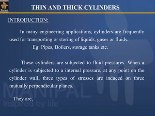
  • 1. THIN AND THICK CYLINDERS They are, In many engineering applications, cylinders are frequently used for transporting or storing of liquids, gases or fluids. Eg: Pipes, Boilers, storage tanks etc. These cylinders are subjected to fluid pressures. When a cylinder is subjected to a internal pressure, at any point on the cylinder wall, three types of stresses are induced on three mutually perpendicular planes. INTRODUCTION:
  • 2. 2. Longitudinal Stress (σL ) – This stress is directed along the length of the cylinder. This is also tensile in nature and tends to increase the length. 3. Radial pressure ( pr ) – It is compressive in nature. Its magnitude is equal to fluid pressure on the inside wall and zero on the outer wall if it is open to atmosphere. 1. Hoop or Circumferential Stress (σC) – This is directed along the tangent to the circumference and tensile in nature. Thus, there will be increase in diameter.
  • 3. σ C σ L 1. Hoop Stress (σC) 2. Longitudinal Stress (σL) 3. Radial Stress (pr) Element on the cylinder wall subjected to these three stresses σ C σ C σC p σ L σ L σ L p p pr σ L σ L σ C σ C pr pr
  • 4. INTRODUCTION: A cylinder or spherical shell is considered to be thin when the metal thickness is small compared to internal diameter. i. e., when the wall thickness, ‘t’ is equal to or less than ‘d/20’, where ‘d’ is the internal diameter of the cylinder or shell, we consider the cylinder or shell to be thin, otherwise thick. Magnitude of radial pressure is very small compared to other two stresses in case of thin cylinders and hence neglected. THIN CYLINDERS
  • 5. Longitudinal axis Longitudinal stress Circumferential stress t The stress acting along the circumference of the cylinder is called circumferential stresses whereas the stress acting along the length of the cylinder (i.e., in the longitudinal direction ) is known as longitudinal stress
  • 6. The bursting will take place if the force due to internal (fluid) pressure (acting vertically upwards and downwards) is more than the resisting force due to circumferential stress set up in the material. p σc σc P - internal pressure (stress) σc –circumferential stress
  • 7. P - internal pressure (stress) σc – circumferential stress dL σc p t
  • 8. EVALUATION OF CIRCUMFERENTIAL or HOOP STRESS (σC): Consider a thin cylinder closed at both ends and subjected to internal pressure ‘p’ as shown in the figure. Let d=Internal diameter, t = Thickness of the wall L = Length of the cylinder. p d t σc σc dl t p d
  • 9. To determine the Bursting force across the diameter: Consider a small length ‘dl’ of the cylinder and an elementary area ‘dA’ as shown in the figure. r p p dθ dl dA dF × × × = × = dθ dl dFx × × × × = θ cos 2 d p dA σc σc dl t p d dθ θ Force on the elementary area, Horizontal component of this force dθ dl × × × = 2 d p dθ dl dFy × × × × = θ sin 2 d p Vertical component of this force
  • 10. The horizontal components cancel out when integrated over semi-circular portion as there will be another equal and opposite horizontal component on the other side of the vertical axis. sin 2 d p force bursting l diametrica Total 0 ∫ × × × × = ∴ π θ dθ dl dA σc σc dl t p θ d dθ [ ] surface. curved the of area projected p d p cos dl 2 d p 0 × = × × = − × × × = dl π θ
  • 11. dl c c × × × = ∴ t σ 2 ) σ stress ntial circumfere to (due force Resisting dl dl × × = × × × d p t σ 2 i.e., c ) 1 ....( .......... .......... t 2 d p σ stress, ntial Circumfere c × × = ∴ dL σc p t force Bursting force Resisting um, equillibri Under =
  • 12. ) 1 ....( .......... .......... t 2 d p σ stress, ntial Circumfere c × × = ∴ Force due to fluid pressure = p × area on which p is acting = p ×(d ×L) (bursting force) Force due to circumferential stress = σc × area on which σc is acting (resisting force) = σc × ( L × t + L ×t ) = σc × 2 L × t Under equilibrium bursting force = resisting force p ×(d ×L) = σc × 2 L × t Assumed as rectangular
  • 13. LONGITUDINAL STRESS (σL): p σL The force, due to pressure of the fluid, acting at the ends of the thin cylinder, tends to burst the cylinder as shown in figure P A B The bursting of the cylinder takes place along the section AB
  • 14. EVALUATION OF LONGITUDINAL STRESS (σL): d 4 π p cylinder) of end (on the force bursting al Longitudin 2 × × = p t σL t d π σ force Resisting L × × × = ∴ t d π force this resisting section cross of Area × × = cylinder. the of material the of stress al Longitudin σ Let L =
  • 15. t d π σ d 4 π p i.e., L 2 × × × = × × ) 2 .........( .......... t 4 d p σ stress, al Longitudin L × × = ∴ L C σ 2 σ (2), & (1) eqs From × = force resisting force bursting um, equillibri Under =
  • 17. EVALUATION OF STRAINS A point on the surface of thin cylinder is subjected to biaxial stress system, (Hoop stress and Longitudinal stress) mutually perpendicular to each other, as shown in the figure. The strains due to these stresses i.e., circumferential and longitudinal are obtained by applying Hooke’s law and Poisson’s theory for elastic materials. σ C=(pd)/(2t) σ C=(pd)/(2t) σL=(pd)/(4t) σ L=(pd)/(4t)
  • 18. E σ μ E σ ε : ε strain, ntial Circumfere L C C C × − = ) 3 ..( .......... .......... .......... μ) 2 ( E t 4 d p d δd ε i.e., C − × × × × = = σ C=(pd)/(2 σC=(pd)/(2t) σ L=(pd)/(4t) σ L=(pd)/(4t) Note: Let δd be the change in diameter. Then ( ) d d d d d d nce circumfere original nce circumfere original nce circumfere final c δ π π δ π ε =       − + = − = μ) 2 ( E σ E σ μ E σ 2 L L L − × = × − × =
  • 19. E σ μ E σ ε : ε strain, al Longitudin C L L L × − = ) 4 ..( .......... .......... .......... μ) 2 1 ( E t 4 d p L δl ε i.e., L × − × × × × = = V v STRAIN, VOLUMETRIC δ Change in volume = δV = final volume – original volume original volume = V = area of cylindrical shell × length L d 4 2 π = μ) 2 1 ( E σ E ) σ 2 ( μ E σ L L L × − × = × × − =
  • 20. final volume = final area of cross section × final length [ ] [ ] [ ] [ ] [ ] L d d L d L d d d L L d L d L L d d d d L L d d δ δ δ δ δ δ δ π δ δ δ π δ δ π 2 ) ( 2 ) ( 4 2 ) ( 4 4 2 2 2 2 2 2 2 + + + + + = + × + + = + × + = [ ] L d d d L L d volume Final L d d and L d L d as such quantities smaller the neglecting δ δ π δ δ δ δ δ 2 2 2 2 2 4 2 ) ( , ) ( + + = [ ] [ ] [ ] L d d d L V L d L d d d L L d V volume in change δ δ π δ π δ δ π δ 2 2 2 2 2 4 4 2 4 + = − + + =
  • 21. [ ] L d 4 π 2 4 π V dv 2 2 × × + = d L d L d δ δ = εL + 2 × εC V dV ) 5 .......( .......... μ) 4 5 ( E t 4 d p V dv i.e., × − × × × = μ) 2 ( E t 4 d p 2 μ) 2 1 ( E t 4 d p − × × × × + × − × × × = d d 2 L L δ δ × + =
  • 24. PROBLEM 1: A thin cylindrical shell is 3m long and 1m in internal diameter. It is subjected to internal pressure of 1.2 MPa. If the thickness of the sheet is 12mm, find the circumferential stress, longitudinal stress, changes in diameter, length and volume . Take E=200 GPa and μ= 0.3. 1. Circumferential stress, σC: σC= (p×d) / (2×t) = (1.2×1000) / (2× 12) = 50 N/mm2 = 50 MPa (Tensile). SOLUTION: 2. Longitudinal stress, σL: σL = (p×d) / (4×t) = σC/2 = 50/2 = 25 N/mm2 = 25 MPa (Tensile). ILLUSTRATIVE PROBLEMS
  • 25. 3. Circumferential strain, εc: Change in length = ε L ×L= 5×10-05 ×3000 = 0.15 mm (Increase). E μ) (2 t) (4 d) (p εc − × × × = Change in diameter, δd = εc ×d = 2.125×10-04 ×1000 = 0.2125 mm (Increase). E μ) 2 (1 t) (4 d) (p εL × − × × × = 4. Longitudinal strain, εL: (Increase) 10 2.125 10 200 0.3) (2 12) (4 1000) (1.2 04 - 3 × = × − × × × = (Increase) 10 5 10 200 0.3) 2 (1 12) (4 1000) (1.2 05 - 3 × = × × − × × × =
  • 27. A copper tube having 45mm internal diameter and 1.5mm wall thickness is closed at its ends by plugs which are at 450mm apart. The tube is subjected to internal pressure of 3 MPa and at the same time pulled in axial direction with a force of 3 kN. Compute: i) the change in length between the plugs ii) the change in internal diameter of the tube. Take ECU = 100 GPa, and μCU = 0.3. A] Due to Fluid pressure of 3 MPa: Longitudinal stress, σL = (p×d) / (4×t) = (3×45) / (4× 1.5) = 22.50 N/mm2 = 22.50 MPa. SOLUTION: Change in length, δL= εL × L = 9 × 10-5 ×450 = +0.0405 mm (increase) E ) μ 2 1 ( t 4 d) (p ε strain, Long. L × − × × × = 5 3 10 9 10 100 ) 3 . 0 2 1 ( 5 . 22 − × = × × − × =
  • 28. Change in diameter, δd= εc × d = 3.825 × 10-4 ×45 = + 0.0172 mm (increase) B] Due to Pull of 3 kN (P=3kN): Area of cross section of copper tube, Ac = π × d × t = π × 45 × 1.5 = 212.06 mm2 Longitudinal strain, ε L = direct stress/E = σ/E = P/(Ac × E) = 3 × 10³ /(212.06 × 100 × 103 ) = 1.415 × 10⁻⁴ Change in length, δL=εL× L= 1.415 × 10-4 ×450= +0.0637mm (increase) E ) μ 2 ( t) (4 d) (p ε strain ntial Circumfere C − × × × = Pd/4t = 22.5 4 3 10 825 . 3 10 100 ) 3 . 0 2 ( 5 . 22 − × = × − × =
  • 29. Lateral strain, εlat= -μ × Longitudinal strain = -μ × εL = - 0.3× 1.415 × 10-4 = -4.245 × 10⁻⁵ Change in diameter, δd = εlat × d = -4.245 × 10-5 ×45 = - 1.91 × 10⁻³ mm (decrease) C) Changes due to combined effects: Change in length = 0.0405 + 0.0637 = + 0.1042 mm (increase) Change in diameter = 0.01721 - 1.91 × 10-3 = + 0.0153 mm (increase)
  • 30. PROBLEM 3: A cylindrical boiler is 800mm in diameter and 1m length. It is required to withstand a pressure of 100m of water. If the permissible tensile stress is 20N/mm2 , permissible shear stress is 8N/mm2 and permissible change in diameter is 0.2mm, find the minimum thickness of the metal required. Take E = 200GPa, and μ = 0.3. Fluid pressure, p = 100m of water = 100×9.81×103 N/m2 = 0.981N/mm2 . SOLUTION: 1. Thickness from Hoop Stress consideration: (Hoop stress is critical than long. Stress) σC = (p×d)/(2×t) 20 = (0.981×800)/(2×t) t = 19.62 mm
  • 31. 2. Thickness from Shear Stress consideration: 3. Thickness from permissible change in diameter consideration (δd=0.2mm): E μ) (2 t) (4 d) (p d δd − × × × = Therefore, required thickness, t = 19.62 mm. t) (8 d) (p τmax × × = 12.26mm. t t) (8 800) (0.981 8 = ∴ × × = 6.67mm t 10 200 ) 3 . 0 2 ( ) t 4 ( ) 800 981 . 0 ( 800 2 . 0 3 = × − × × × =
  • 32. PROBLEM 4: A cylindrical boiler has 450mm in internal diameter, 12mm thick and 0.9m long. It is initially filled with water at atmospheric pressure. Determine the pressure at which an additional water of 0.187 liters may be pumped into the cylinder by considering water to be incompressible. Take E = 200 GPa, and μ = 0.3. Additional volume of water, δV = 0.187 liters = 0.187×10⁻³ m3 = 187×103 mm3 SOLUTION: 3 6 3 2 mm 10 143.14 ) 10 9 . 0 ( 450 4 π V × = × × × = μ) 4 5 ( E t 4 d p V dV × − × × × = Solving, p=7.33 N/mm2 ) 33 . 0 4 5 ( 10 200 12 4 450 p 10 143.14 10 187 3 6 3 × − × × × × = × ×
  • 33. JOINT EFFICIENCY Longitudinal rivets Circumferential rivets Steel plates of only particular lengths and width are available. Hence whenever larger size cylinders (like boilers) are required, a number of plates are to be connected. This is achieved by using riveting in circumferential and longitudinal directions as shown in figure. Due to the holes for rivets, the net area of cross section decreases and hence the stresses increase.
  • 34. JOINT EFFICIENCY The cylindrical shells like boilers are having two types of joints namely Longitudinal and Circumferential joints. Due to the holes for rivets, the net area of cross section decreases and hence the stresses increase. If the efficiencies of these joints are known, the stresses can be calculated as follows. Let η L= Efficiency of Longitudinal joint and η C = Efficiency of Circumferential joint. ...(1) .......... η t 2 d p σ L C × × × = Circumferential stress is given by,
  • 35. ...(2) .......... η t 4 d p σ C L × × × = Note: In longitudinal joint, the circumferential stress is developed and in circumferential joint, longitudinal stress is developed. Longitudinal stress is given by, Circumferential rivets Longitudinal rivets
  • 36. If A is the gross area and Aeff is the effective resisting area then, Efficiency = Aeff/A Bursting force = p L d Resisting force = σc ×Aeff = σc ×ηL ×A = σc ×ηL ×2 t L Where η L=Efficiency of Longitudinal joint Bursting force = Resisting force p L d = σc ×ηL × 2 t L ...(1) .......... η t 2 d p σ L C × × × =
  • 37. If η c=Efficiency of circumferential joint Efficiency = Aeff/A Bursting force = (π d2 /4)p Resisting force = σL ×A′eff =σL ×ηc ×A′ = σL ×ηc ×π d t Where η L=Efficiency of circumferential joint Bursting force = Resisting force ...(2) .......... η t 4 d p σ C L × × × =
  • 38. A cylindrical tank of 750mm internal diameter, 12mm thickness and 1.5m length is completely filled with an oil of specific weight 7.85 kN/m3 at atmospheric pressure. If the efficiency of longitudinal joints is 75% and that of circumferential joints is 45%, find the pressure head of oil in the tank. Also calculate the change in volume. Take permissible tensile stress of tank plate as 120 MPa and E = 200 GPa, and μ = 0.3. Let p = max permissible pressure in the tank. Then we have, σL= (p×d)/(4×t) η C 120 = (p×750)/(4×12) 0.45 p = 3.456 MPa. SOLUTION: Also, σ C= (p×d)/(2×t) η L 120 = (p×750)/(2×12) 0.75 p = 2.88 MPa.
  • 39. Max permissible pressure in the tank, p = 2.88 MPa. μ) 4 5 ( E) t (4 d) (p V dv Strain, Vol. × − × × × × = litres. 0.567 m 10 0.567 . mm 10 567 . 0 1500 750 4 π 10 8.55 V 10 8.55 dv 10 8.55 0.3) 4 - (5 ) 10 200 12 (4 750) (2.88 3 3 - 3 6 2 4 - 4 - 4 - 3 = × = × = × × × × = × × = × = × × × × × × =
  • 40. A boiler shell is to be made of 15mm thick plate having a limiting tensile stress of 120 N/mm2 . If the efficiencies of the longitudinal and circumferential joints are 70% and 30% respectively determine; i) The maximum permissible diameter of the shell for an internal pressure of 2 N/mm2 . (ii) Permissible intensity of internal pressure when the shell diameter is 1.5m. (i) To find the maximum permissible diameter of the shell for an internal pressure of 2 N/mm2 : SOLUTION: η t 2 d p σ e., i. L c × × × = a) Let limiting tensile stress = Circumferential stress = σ c = 120N/mm2 . d = 1260 mm 7 . 0 5 1 2 d 2 120 × × × =
  • 41. η t 4 d p σ e., i. C L × × × = b) Let limiting tensile stress = Longitudinal stress = σ L = 120N/mm2 . The maximum diameter of the cylinder in order to satisfy both the conditions = 1080 mm. d = 1080 mm . 3 . 0 5 1 4 d 2 120 × × × =
  • 42. The maximum permissible pressure = 1.44 N/mm2 . (ii) To find the permissible pressure for an internal diameter of 1.5m: (d=1.5m=1500mm) a) Let limiting tensile stress = Circumferential stress = σ c = 120N/mm2 . η t 2 d p σ e., i. L c × × × = b) Let limiting tensile stress = Longitudinal stress = σ L = 120N/mm2 . η t 4 d p σ e., i. C L × × × = . N/mm 1.68 p 7 . 0 5 1 2 500 1 p 120 2 = × × × = . N/mm 1.44 p 3 . 0 5 1 4 500 1 p 120 2 = × × × =
  • 43. PROBLEM 1: Calculate the circumferential and longitudinal strains for a boiler of 1000mm diameter when it is subjected to an internal pressure of 1MPa. The wall thickness is such that the safe maximum tensile stress in the boiler material is 35 MPa. Take E=200GPa and μ= 0.25. (Ans: ε C=0.0001531, ε L=0.00004375) PROBLEM 2: A water main 1m in diameter contains water at a pressure head of 120m. Find the thickness of the metal if the working stress in the pipe metal is 30 MPa. Take unit weight of water = 10 kN/m3 . (Ans: t=20mm) PROBLEMS FOR PRACTICE
  • 44. THIN AND THICK CYLINDERS -33 PROBLEM 3: A gravity main 2m in diameter and 15mm in thickness. It is subjected to an internal fluid pressure of 1.5 MPa. Calculate the hoop and longitudinal stresses induced in the pipe material. If a factor of safety 4 was used in the design, what is the ultimate tensile stress in the pipe material? (Ans: σC=100 MPa, σL=50 MPa, σU=400 MPa) PROBLEM 4: At a point in a thin cylinder subjected to internal fluid pressure, the value of hoop strain is 600×10-4 (tensile). Compute hoop and longitudinal stresses. How much is the percentage change in the volume of the cylinder? Take E=200GPa and μ= 0.2857. (Ans: σC=140 MPa, σL=70 MPa, %age change=0.135%.)
  • 45. THIN AND THICK CYLINDERS -34 PROBLEM 5: A cylindrical tank of 750mm internal diameter and 1.5m long is to be filled with an oil of specific weight 7.85 kN/m3 under a pressure head of 365 m. If the longitudinal joint efficiency is 75% and circumferential joint efficiency is 40%, find the thickness of the tank required. Also calculate the error of calculation in the quantity of oil in the tank if the volumetric strain of the tank is neglected. Take permissible tensile stress as 120 MPa, E=200GPa and μ= 0.3 for the tank material. (Ans: t=12 mm, error=0.085%.)
  • 47. INTRODUCTION: The thickness of the cylinder is large compared to that of thin cylinder. i. e., in case of thick cylinders, the metal thickness ‘t’ is more than ‘d/20’, where ‘d’ is the internal diameter of the cylinder. Magnitude of radial stress (pr) is large and hence it cannot be neglected. The circumferential stress is also not uniform across the cylinder wall. The radial stress is compressive in nature and circumferential and longitudinal stresses are tensile in nature. Radial stress and circumferential stresses are computed by using ‘Lame’s equations’.
  • 48. LAME’S EQUATIONS (Theory) : 4. The material is homogeneous, isotropic and obeys Hooke’s law. (The stresses are within proportionality limit). 1. Plane sections of the cylinder normal to its axis remain plane and normal even under pressure. 2. Longitudinal stress (σL) and longitudinal strain (εL) remain constant throughout the thickness of the wall. 3. Since longitudinal stress (σL) and longitudinal strain (εL) are constant, it follows that the difference in the magnitude of hoop stress and radial stress (pr) at any point on the cylinder wall is a constant. ASSUMPTIONS:
  • 49. LAME’S EQUATIONS FOR RADIAL PRESSURE AND CIRCUMFERENTIAL STRESS Consider a thick cylinder of external radius r1 and internal radius r2, containing a fluid under pressure ‘p’ as shown in the fig. Let ‘L’ be the length of the cylinder. p r2 r1 p
  • 50. Consider an elemental ring of radius ‘r’ and thickness ‘δr’ as shown in the above figures. Let pr and (pr+ δpr) be the intensities of radial pressures at inner and outer faces of the ring. pr pr+δpr r2 r1 r pr pr+δpr r2 r1 r σc σc r δr Pr pr+δpr External pressure
  • 51. Consider the longitudinal section XX of the ring as shown in the fig. The bursting force is evaluated by considering the projected area, ‘2×r×L’ for the inner face and ‘2×(r+δr)×L’ for the outer face . The net bursting force, P = pr×2×r×L - (pr+δpr)×2×(r+δr)×L =( -pr× δr - r×δpr - δpr × δr) 2L Bursting force is resisted by the hoop tensile force developing at the level of the strip i.e., Fr=σc×2 ×δr×L L r pr pr+δpr r+δr X X
  • 52. Thus, for equilibrium, P = Fr (-pr× δr - r×δpr- δpr × δr) 2L = σ c×2×δr×L -pr× δr - r×δpr- δpr × δr = σ c×δr Neglecting products of small quantities, (i.e., δpr × δr) σ c = - pr – (r× δpr )/ δr ...…………….(1) Longitudinal strain is constant. Hence we have, since σL, E and μ are constants (σc – Pr) should be constant . Let it be equal to 2a. Thus constant E p μ E σ μ E σ r C L = × + × − Since Pr is compressive ε L = constant ) p σ ( μ E σ r C L = − − E ε L =
  • 53. σ c- pr = 2a, i.e., σc = pr + 2a, ………………(2) From (1), pr+ 2a = - pr – (r× δpr ) / δr r r r p - a) p ( 2 δ δ × = + r ) 3 .( .......... a) p ( p 2 r r r + = × − δ δ r i. e., Integrating, (-2 ×loge r) + c = loge (pr + a) Where c is constant of integration. Let it be taken as loge b, where ‘b’ is another constant. Thus, loge (pr+a) = -2 ×loge r + loge b = - loge r2 + loge b = loge 2 r b
  • 54. .....(4) .......... a r b p stress, radial or, r b a p i.e., 2 r 2 r − = = + The equations (4) & (5) are known as “Lame’s Equations” for radial pressure and hoop stress at any specified point on the cylinder wall. Thus, r1≤r ≤r2. a 2 a b a 2 p σ stress, Hoop 2 r c + − = + = r .......(5) .......... .......... a r b σ i.e., 2 c + = Substituting it in equation 2, we get
  • 55. ANALYSIS FOR LONGITUDINAL STRESS Consider a transverse section near the end wall as shown in the fig. Bursting force, P =π×r2 2 ×p Resisting force is due to longitudinal stress ‘σ L’. i.e., FL= σ L× π ×(r1 2 -r2 2 ) For equilibrium, FL= P σ L× π ×(r1 2 -r2 2 )= π ×r2 2 ×p Therefore, longitudinal stress, (Tensile) ) r (r r p σ 2 2 2 1 2 2 L − × = p p r2 r1 σL σ L σL σL L
  • 56. NOTE: 1. Variations of Hoop stress and Radial stress are parabolic across the cylinder wall. 2. At the inner edge, the stresses are maximum. 3. The value of ‘Permissible or Maximum Hoop Stress’ is to be considered on the inner edge. 4. The maximum shear stress (σ max) and Hoop, Longitudinal and radial strains (εc, εL, εr) are calculated as in thin cylinder but separately for inner and outer edges.
  • 57. ILLUSTRATIVE PROBLEMS PROBLEM 1: A thick cylindrical pipe of external diameter 300mm and internal diameter 200mm is subjected to an internal fluid pressure of 20N/mm2 and external pressure of 5 N/mm2 . Determine the maximum hoop stress developed and draw the variation of hoop stress and radial stress across the thickness. Show at least four points for each case. SOLUTION: External diameter = 300mm. External radius, r1=150mm. Internal diameter = 200mm. Internal radius, r2=100mm. Lame’s equations: For Hoop stress, .........(1) For radial stress, .........(2) a r b σ 2 c + = a r b p 2 r − =
  • 58. Boundary conditions: At r =100mm (on the inner face), radial pressure = 20N/mm2 i.e., Similarly, at r =150mm (on the outer face), radial pressure = 5N/mm2 i.e., ) ........(3 .......... a 100 b 20 2 − = ) ........(4 .......... a 150 b 5 2 − = ..(5) .......... 7 r 2,70,000 σ 2 c + = ..(6) .......... 7 r 2,70,000 p 2 r − = Solving equations (3) & (4), we get a = 7, b = 2,70,000. Lame’s equations are, for Hoop stress, For radial stress,
  • 59. To draw variations of Hoop stress & Radial stress : At r =100mm (on the inner face), (Comp) MPa 20 7 100 2,70,000 p stress, Radial (Tensile) MPa 34 7 100 2,70,000 σ stress, Hoop 2 r 2 c = − = = + = At r =120mm, (Comp) MPa 11.75 7 120 2,70,000 p stress, Radial (Tensile) MPa 25.75 7 120 2,70,000 σ stress, Hoop 2 r 2 c = − = = + = At r =135mm, (Comp) MPa 7.81 7 135 2,70,000 p stress, Radial (Tensile) MPa 21.81 7 135 2,70,000 σ stress, Hoop 2 r 2 c = − = = + =
  • 60. (Comp) MPa 5 7 150 2,70,000 p stress, Radial (Tensile) MPa 19 7 150 2,70,000 σ stress, Hoop 150mm, r At 2 r 2 c = − = = + = = Variation of Hoop stress & Radial stress Variation of Hoop Stress-Tensile (Parabolic) Variation of Radial Stress –Comp (Parabolic)
  • 61. PROBLEM 2: Find the thickness of the metal required for a thick cylindrical shell of internal diameter 160mm to withstand an internal pressure of 8 N/mm2 . The maximum hoop stress in the section is not to exceed 35 N/mm2 . SOLUTION: Internal radius, r2=80mm. ......(2) .......... a r b p stress, Radial for (1) .......... .......... a r b σ Stress, Hoop for are, equations s Lame' 2 r 2 c − = + =
  • 63. . r r at 0 p i.e., 0. pressure face, outer On the 1 r = = = 20.96mm. r - r metal the of Thickness 2 1 = = ∴ 100.96mm. r 5 . 13 r 1,37,600 0 1 2 1 = ∴ − = ∴
  • 64. PROBLEM 3: A thick cylindrical pipe of outside diameter 300mm and internal diameter 200mm is subjected to an internal fluid pressure of 14 N/mm2 . Determine the maximum hoop stress developed in the cross section. What is the percentage error if the maximum hoop stress is calculated by the equations for thin cylinder? SOLUTION: Internal radius, r2=100mm. External radius, r1=150mm . Lame’s equations: For Hoop stress, .........(1) For radial pressure, .........(2) a r b σ 2 c + = a r b p 2 r − =
  • 65. Boundary conditions: At x =100mm Pr = 14N/mm2 i.e., Similarly, at x =150mm Pr = 0 i.e., ) ........(1 .......... a 100 b 14 2 − = ) ........(2 .......... a 150 b 0 2 − = ..(3) .......... 2 . 11 r 22,500 σ stress, Hoop for equation s Lame' 2 r + = ∴ Solving, equations (1) & (2), we get a =11.2, b = 2,52,000.
  • 66. MPa. 36.4 2 . 11 100 252000 σ 2 max = + = Max hoop stress on the inner face (where x=100mm): . 23.08% 100 ) 36.4 28 - 36.4 ( error Percentage = × = 14MPa. p and 50mm t 200mm, D e wher t 2 d p σ formula, cylinder By thin max = = = × × = MPa. 28 50 2 200 14 σmax = × × = ∴
  • 67. PROBLEM 4: The principal stresses at the inner edge of a cylindrical shell are 81.88 MPa (T) and 40MPa (C). The internal diameter of the cylinder is 180mm and the length is 1.5m. The longitudinal stress is 21.93 MPa (T). Find, (i) Max shear stress at the inner edge. (ii) Change in internal diameter. (iii)Change in length. (iv) Change in volume. Take E=200 GPa and μ=0.3. SOLUTION: 2 (-40) - 81.88 2 p - σ τ : face inner on the stress shear Max i) r C max = = = 60.94 MPa
  • 70. PROBLEM 5: Find the max internal pressure that can be allowed into a thick pipe of outer diameter of 300mm and inner diameter of 200mm so that tensile tress in the metal does not exceed 16 MPa if, (i) there is no external luid pressure, (ii) there is a fluid pressure of 4.2 MPa. SOLUTION: External radius, r1=150mm. Internal radius, r2=100mm. Boundary conditions: At r=100mm , σc = 16N/mm2 At r=150mm , Pr = 0 Case (i) – When there is no external fluid pressure:
  • 71. ) ........(2 .......... a 150 b 0 ) ........(1 .......... a 100 b 16 i.e., 2 2 − = + = Solving we get, a = 4.92 & b=110.77×10³ ) ........(4 .......... 92 . 4 10 110.77 p ) ........(3 .......... 92 . 4 10 110.77 σ that so 2 3 r 2 3 c − × = + × = r r MPa. 6.16 92 . 4 00 1 10 110.77 p 100mm, r where face inner on the pressure Fluid 2 3 r = − × = =
  • 72. Boundary conditions: At r=100mm , σc= 16 N/mm2 At r=150mm , pr= 4.2 MPa. Case (ii) – When there is an external fluid pressure of 4.2 MPa: ) ........(2 .......... a 150 b 4.2 ) ........(1 .......... a 100 b 16 i.e., 2 2 − = + = Solving we get, a = 2.01 & b=139.85×10³ ) ........(4 .......... 01 . 2 10 139.85 p ) ........(3 .......... 01 . 2 10 139.85 σ that so 2 3 r 2 3 r − × = + × = r r
  • 74. PROBLEM 1: A pipe of 150mm internal diameter with the metal thickness of 50mm transmits water under a pressure of 6 MPa. Calculate the maximum and minimum intensities of circumferential stresses induced. (Ans: 12.75 MPa, 6.75 MPa) PROBLEM 2: Determine maximum and minimum hoop stresses across the section of a pipe of 400mm internal diameter and 100mm thick when a fluid under a pressure of 8N/mm2 is admitted. Sketch also the radial pressure and hoop stress distributions across the thickness. (Ans: σmax=20.8 N/mm2 ,σmin=12.8 N/mm2 ) PROBLEM 3: A thick cylinder with external diameter 240mm and internal diameter ‘D’ is subjected to an external pressure of 50 MPa. Determine the diameter ‘D’ if the maximum hoop stress in the cylinder is not to exceed 200 MPa. (Ans: 169.7 mm) PROBLEMS FOR PRACTICE
  • 75. THIN AND THICK CYLINDERS -63 PROBLEM 4: A thick cylinder of 1m inside diameter and 7m long is subjected to an internal fluid pressure of 40 MPa. Determine the thickness of the cylinder if the maximum shear stress in the cylinder is not to exceed 65 MPa. What will be the increase in the volume of the cylinder? E=200 GPa, μ=0.3. (Ans: t=306.2mm, δv=5.47×10⁻³ m3 ) PROBLEM 5: A thick cylinder is subjected to both internal and external pressure. The internal diameter of the cylinder is 150mm and the external diameter is 200mm. If the maximum permissible stress in the cylinder is 20 N/mm2 and external radial pressure is 4 N/mm2 , determine the intensity of internal radial pressure. (Ans: 10.72 N/mm2 )