This document contains a table of contents for a textbook on mechanical engineering. The table of contents lists 14 chapters, beginning with "Stress" and ending with "Buckling of Columns". Each chapter is numbered and given a page range. The document provides an outline of the topics that will be covered in the textbook.


![535
© 2010 Pearson Education, Inc., Upper Saddle River, NJ. All rights reserved.This material is protected under all copyright laws as they currently
exist. No portion of this material may be reproduced, in any form or by any means, without permission in writing from the publisher.
a) Ans.
b)
Ans.
c) From FBD(a)
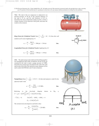
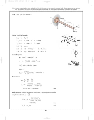
Ans.(tavg)b =
Fb
A
-
25312.5
p
4(0.01)2
= 322 MPa
Fb = 25.3 kN
+ c ©Fy = 0; Fb - 79.1(106
)[(0.008)(0.04)] = 0
s1¿ = 79.1MPa
126.56 (106
)(0.05)(0.008) = s1¿(2)(0.04)(0.008)
s1 =
pr
t
=
1.35(106
)(0.75)
0.008
= 126.56(106
) = 127 MPa
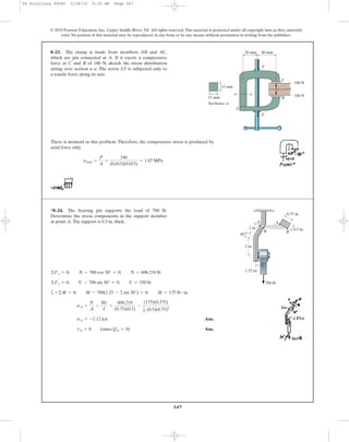
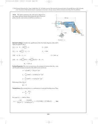
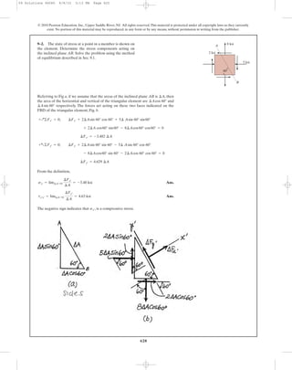
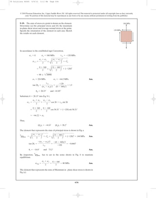
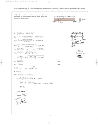
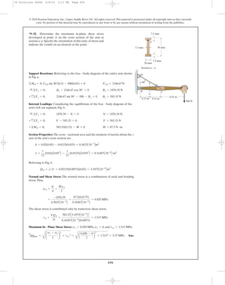
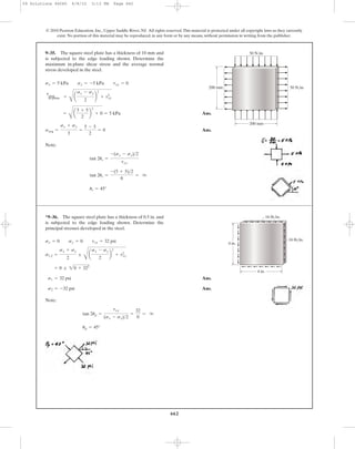
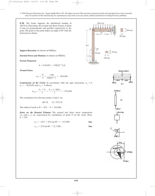
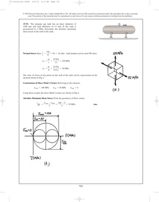
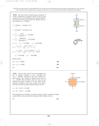
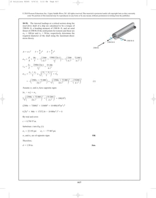
8–7. A boiler is constructed of 8-mm thick steel plates that
are fastened together at their ends using a butt joint
consisting of two 8-mm cover plates and rivets having a
diameter of 10 mm and spaced 50 mm apart as shown. If the
steam pressure in the boiler is 1.35 MPa, determine (a) the
circumferential stress in the boiler’s plate apart from
the seam,(b) the circumferential stress in the outer cover plate
along the rivet line a–a,and (c) the shear stress in the rivets.
a
8 mm
50 mm a
0.75 m
08 Solutions 46060 5/28/10 8:34 AM Page 535](https://image.slidesharecdn.com/ch08-10combinedloadstransformations-190927203142/85/Ch08-10-combined-loads-transformations-5-320.jpg)
![536
© 2010 Pearson Education, Inc., Upper Saddle River, NJ. All rights reserved.This material is protected under all copyright laws as they currently
exist. No portion of this material may be reproduced, in any form or by any means, without permission in writing from the publisher.
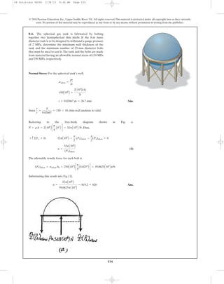
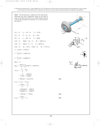
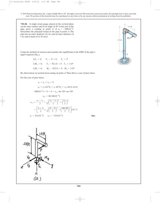
Normal Stress: For the cylindrical portion of the tank, the hoop stress is twice as
large as the longitudinal stress.
Ans.
For the hemispherical cap,
Ans.
Since , thin-wall analysis is valid.
Referring to the free-body diagram of the per meter length of the cylindrical
portion, Fig. a, where , we have
(1)
The allowable tensile force for each bolt is
Substituting this result into Eq. (1),
Ans.nc = 48.89 = 49 bolts>meter
(Pb)allow = sallowAb = 250A106
B c
p
4
A0.0252
B d = 122.72A103
B N
nc =
6A106
B
(Pb)allow
+ c ©Fy = 0; 12A106
B - nc(Pb)allow - nc(Pb)allow = 0
P = pA = 3A106
B[4(1)] = 12A106
B N
r
t
6 10
ts = 0.02m = 20 mm
sallow =
pr
t
; 150A106
B =
3A106
B(2)
2ts
tc = 0.04m = 40mm
sallow =
pr
t
; 150A106
B =
3A106
B(2)
tc
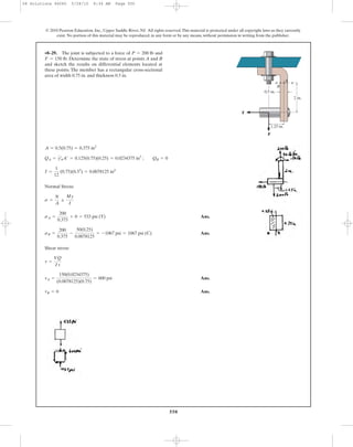
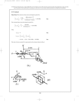
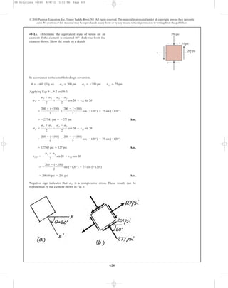
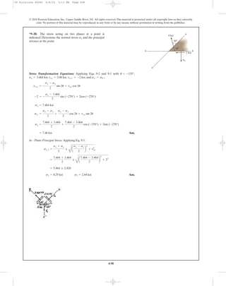
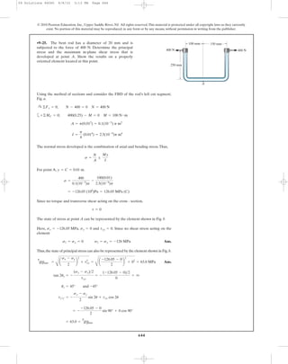
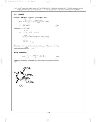
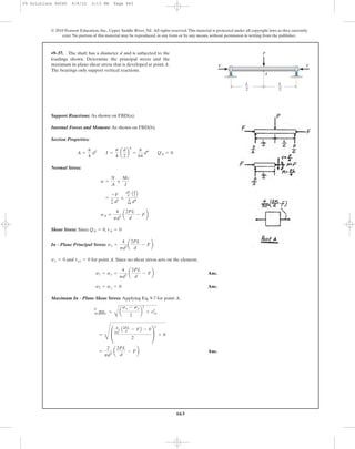
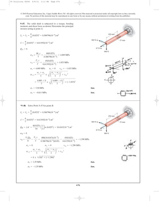
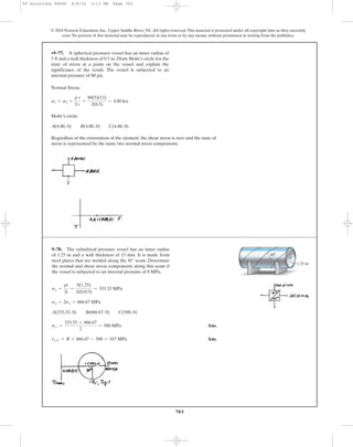
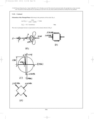
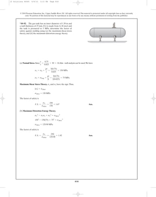
*8–8. The gas storage tank is fabricated by bolting together
two half cylindrical thin shells and two hemispherical shells
as shown. If the tank is designed to withstand a pressure
of 3 MPa, determine the required minimum thickness of
the cylindrical and hemispherical shells and the minimum
required number of longitudinal bolts per meter length at
each side of the cylindrical shell. The tank and the 25 mm
diameter bolts are made from material having an allowable
normal stress of 150 MPa and 250 MPa, respectively. The
tank has an inner diameter of 4 m.
08 Solutions 46060 5/28/10 8:34 AM Page 536](https://image.slidesharecdn.com/ch08-10combinedloadstransformations-190927203142/85/Ch08-10-combined-loads-transformations-6-320.jpg)


![540
© 2010 Pearson Education, Inc., Upper Saddle River, NJ. All rights reserved.This material is protected under all copyright laws as they currently
exist. No portion of this material may be reproduced, in any form or by any means, without permission in writing from the publisher.
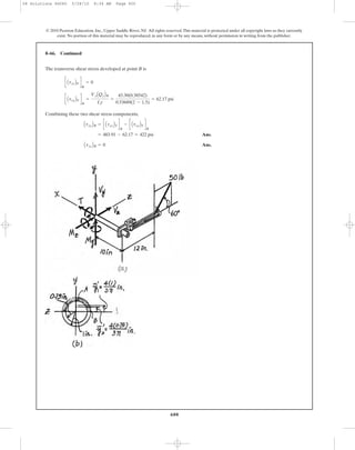
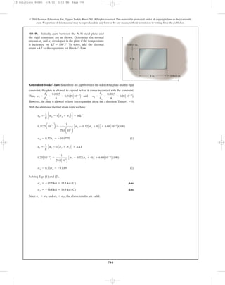
Equilibrium for the Ring: Form the FBD
Hoop Stress and Strain for the Ring:
Using Hooke’s Law
[1]
However, .
Then, from Eq. [1]
Ans.dri =
pri
2
E(rs - ri)
dri
ri
=
pri
E(rs - ri)
e1 =
2p(ri)1 - 2pri
2pr
=
(ri)1 - ri
ri
=
dri
ri
e1 =
s1
E
=
pri
E(rs - ri)
s1 =
P
A
=
priw
(rs - ri)w
=
pri
rs - ri
:+ ©Fx = 0; 2P - 2pri w = 0 P = pri w
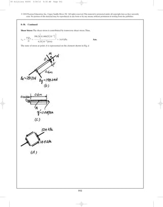
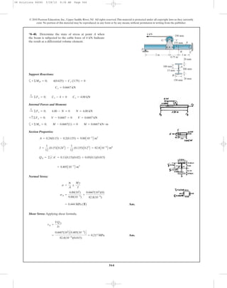
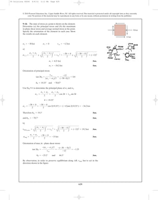
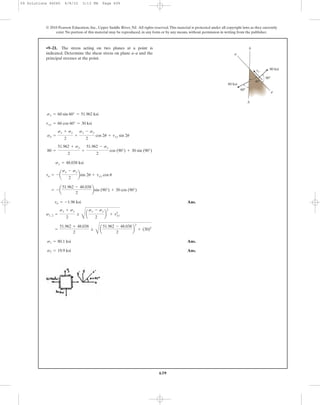
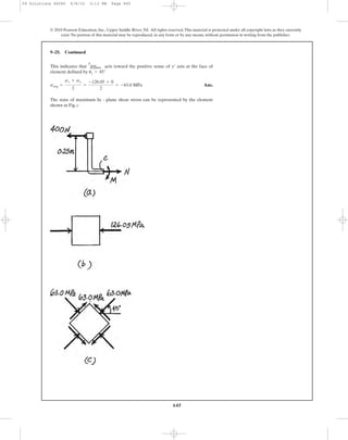
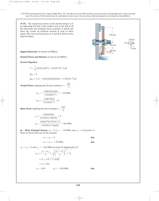
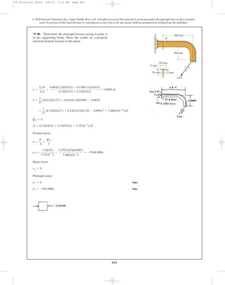
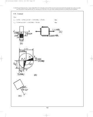
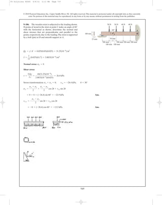
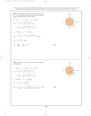
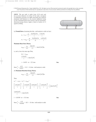
8–14. The ring, having the dimensions shown, is placed
over a flexible membrane which is pumped up with a
pressure p. Determine the change in the internal radius of
the ring after this pressure is applied. The modulus of
elasticity for the ring is E.
p
ro
w
ri
08 Solutions 46060 5/28/10 8:34 AM Page 540](https://image.slidesharecdn.com/ch08-10combinedloadstransformations-190927203142/85/Ch08-10-combined-loads-transformations-10-320.jpg)
![541
© 2010 Pearson Education, Inc., Upper Saddle River, NJ. All rights reserved.This material is protected under all copyright laws as they currently
exist. No portion of this material may be reproduced, in any form or by any means, without permission in writing from the publisher.
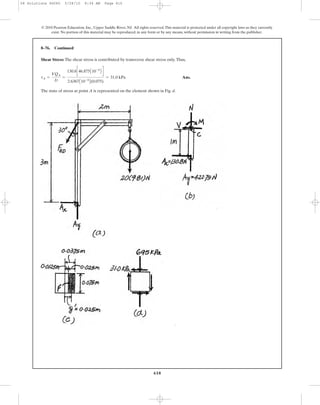
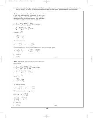
Equilibrium for the Ring: From the FBD
Hoop Stress and Strain for the Ring:
Using Hooke’s law
[1]
However, .
Then, from Eq. [1]
Compatibility: The pressure between the rings requires
[2]
From the result obtained above
Substitute into Eq. [2]
Ans.p =
E(r2 - r3)
r2
2
r2 - r1
+
r3
2
r4 - r3
pr2
2
E(r2 - r1)
+
pr3
2
E(r4 - r3)
= r2 - r3
dr2 =
pr2
2
E(r2 - r1)
dr3 =
pr3
2
E(r4 - r3)
dr2 + dr3 = r2 - r3
dri =
pri
2
E(ro - ri)
dri
ri
=
pri
E(ro - ri)
e1 =
2p(ri)1 - 2pri
2pr
=
(ri)1 - ri
ri
=
dri
ri
e1 =
s1
E
=
pri
E(ro - ri)
s1 =
P
A
=
priw
(ro - ri)w
=
pri
ro - ri
:+ ©Fx = 0; 2P - 2priw = 0 P = priw
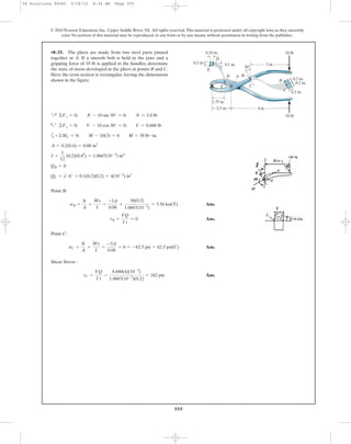
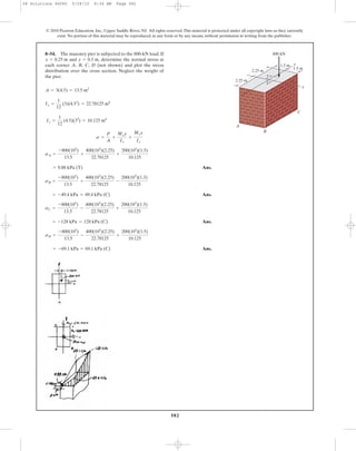
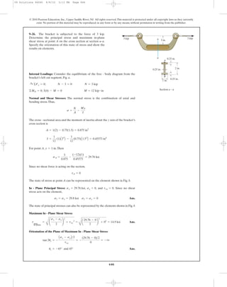
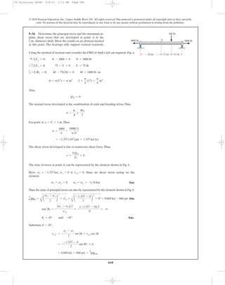
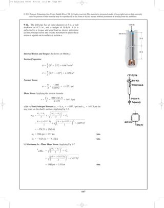
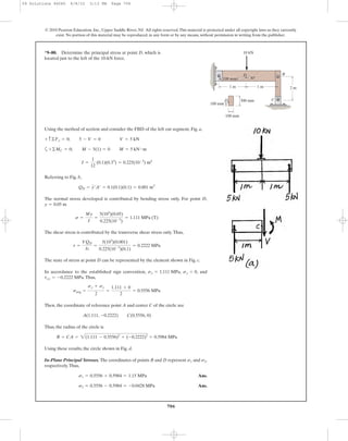
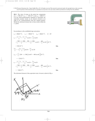
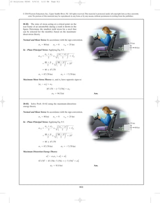
8–15. The inner ring A has an inner radius and outer
radius . Before heating, the outer ring B has an inner
radius and an outer radius , and . If the outer ring
is heated and then fitted over the inner ring, determine the
pressure between the two rings when ring B reaches the
temperature of the inner ring.The material has a modulus of
elasticity of E and a coefficient of thermal expansion of .a
r2 7 r3r4r3
r2
r1
r1
r2
r3
A
B
r4
08 Solutions 46060 5/28/10 8:34 AM Page 541](https://image.slidesharecdn.com/ch08-10combinedloadstransformations-190927203142/85/Ch08-10-combined-loads-transformations-11-320.jpg)


= 667 psi
sD = 0
+©MA = 0; -F(2.5) + 4(10) = 0; F = 16 lb
8–34. Solve Prob. 8–33 for points D and E.
4 in.2.5 in.
10 lb
10 lb
30Њ
3 in.
B
C
A
0.2 in.
0.2 in.
B
C
0.2 in.
D
E
D
E
0.18 in.
0.2 in.
1.75 in.
0.1 in.
08 Solutions 46060 5/28/10 8:34 AM Page 556](https://image.slidesharecdn.com/ch08-10combinedloadstransformations-190927203142/85/Ch08-10-combined-loads-transformations-26-320.jpg)


![573
© 2010 Pearson Education, Inc., Upper Saddle River, NJ. All rights reserved.This material is protected under all copyright laws as they currently
exist. No portion of this material may be reproduced, in any form or by any means, without permission in writing from the publisher.
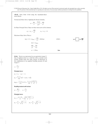
Section Properties:
Internal Forces and Moment: As shown on FBD.
Normal Stress:
[1]
[2]
In order to have maximum normal stress, .
Since , then
2a - 4x = 0 x = 0.500a
P
a(a + x)3
Z 0
-
P
a(a + x)3
(2a - 4x) = 0
dsA
dx
= -
P
a
B
(a + x)2
(4) - (4x + a)(2)(a + x)(1)
(a + x)4 R = 0
dsA
dx
= 0
=
P
a
B
2x - a
(a + x)2 R
sB =
P
a
B
-1
a + x
+
3x
(a + x)2 R
= -
P
a
B
4x + a
(a + x)2 R
sA = -
P
a
B
1
a + x
+
3x
(a + x)2 R
=
P
a
B
-1
a + x
;
3x
(a + x)2 R
=
-P
a(a + x)
;
0.5PxC1
2 (a + x)D
a
12 (a + x)3
s =
N
A
;
Mc
I
I =
1
12
(a) (a + x)3
=
a
12
(a + x)3
A = a(a + x)
w = a + x
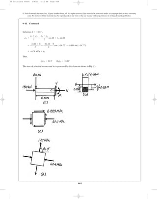
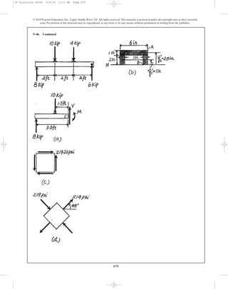
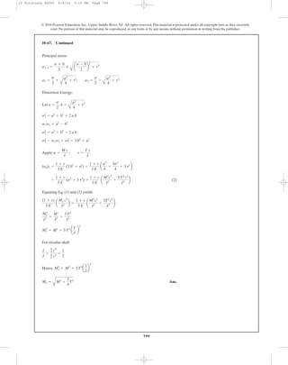
8–46. The support is subjected to the compressive load P.
Determine the absolute maximum and minimum normal
stress acting in the material.
P
a—
2
a—
2
a—
2
a—
2
08 Solutions 46060 5/28/10 8:34 AM Page 573](https://image.slidesharecdn.com/ch08-10combinedloadstransformations-190927203142/85/Ch08-10-combined-loads-transformations-43-320.jpg)
![574
Substituting the result into Eq. [1] yields
Ans.
In order to have minimum normal stress, .
Since , then
Substituting the result into Eq. [2] yields
Ans.smin =
P
a
B
2(2a) - a
(a + 2a)2 R =
P
3a2
(T)
4a - 2x = 0 x = 2a
P
a(a + x)3
Z 0
P
a(a + x)3
(4a - 2x) = 0
dsB
dx
=
P
a
B
(a + x)2
(2) - (2x - a)(2)(a + x)(1)
(a + x)4 R = 0
dsB
dx
= 0
= -
1.33P
a2
=
1.33P
a2
(C)
smax = -
P
a
B
4(0.500a) + a
(a + 0.5a)2 R
8–46. Continued
© 2010 Pearson Education, Inc., Upper Saddle River, NJ. All rights reserved.This material is protected under all copyright laws as they currently
exist. No portion of this material may be reproduced, in any form or by any means, without permission in writing from the publisher.
08 Solutions 46060 5/28/10 8:34 AM Page 574](https://image.slidesharecdn.com/ch08-10combinedloadstransformations-190927203142/85/Ch08-10-combined-loads-transformations-44-320.jpg)
![575
© 2010 Pearson Education, Inc., Upper Saddle River, NJ. All rights reserved.This material is protected under all copyright laws as they currently
exist. No portion of this material may be reproduced, in any form or by any means, without permission in writing from the publisher.
r
P
Section Properties:
Internal Force and Moment: As shown on FBD.
Normal Stress:
[1]
[2]
In order to have maximum normal stress, .
Since , then
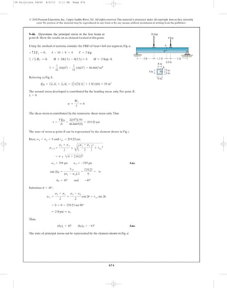
Substituting the result into Eq. [1] yields
Ans.= -
0.368P
r2
=
0.368P
r2
(C)
smax = -
P
p
B
r + 2.5(0.400r)
[r + 0.5(0.400r)]3 R
r - 2.5x = 0 x = 0.400r
P
p(r + 0.5x)4
Z 0
-
P
p(r + 0.5x)4
(r - 2.5x) = 0
dsA
dx
= -
P
p
B
(r + 0.5x)3
(2.5) - (r + 2.5x)(3)(r + 0.5x)2
(0.5)
(r + 0.5x)6
R = 0
dsA
dx
= 0
=
P
p
B
1.5x - r
(r + 0.5x)3 R
sB =
P
p
B
–1
(r + 0.5x)2
+
2x
(r + 0.5x)3 R
= -
P
p
B
r + 2.5x
(r + 0.5x)3 R
sA = -
P
p
B
1
(r + 0.5x)2
+
2x
(r + 0.5x)3 R
=
P
p
B
–1
(r + 0.5x)2
;
2x
(r + 0.5x)3 R
=
–P
p(r + 0.5x)2
;
0.5Px(r + 0.5x)
p
4 (r + 0.5)4
s =
N
A
;
Mc
I
I =
p
4
(r + 0.5x)4
A = p(r + 0.5x)2
d¿ = 2r + x
8–47. The support is subjected to the compressive load P.
Determine the maximum and minimum normal stress acting
in the material.All horizontal cross sections are circular.
08 Solutions 46060 5/28/10 8:34 AM Page 575](https://image.slidesharecdn.com/ch08-10combinedloadstransformations-190927203142/85/Ch08-10-combined-loads-transformations-45-320.jpg)
![576
8–47. Continued
© 2010 Pearson Education, Inc., Upper Saddle River, NJ. All rights reserved.This material is protected under all copyright laws as they currently
exist. No portion of this material may be reproduced, in any form or by any means, without permission in writing from the publisher.
In order to have minimum normal stress, .
Since , then
Substituting the result into Eq. [2] yields
Ans.smin =
P
p
B
1.5(2.00r) - r
[r + 0.5(2.00r)]3 R =
0.0796P
r2
(T)
3r - 1.5x = 0 x = 2.00r
P
p(r + 0.5x)4
Z 0
P
p(r + 0.5x)4
(3r - 1.5x) = 0
dsB
dx
=
P
p
B
(r + 0.5x)3
(1.5) - (1.5x - r)(3)(r + 0.5x)2
(0.5)
(r + 0.5x)6
R = 0
dsB
dx
= 0
*8–48. The post has a circular cross section of radius c.
Determine the maximum radius e at which the load can be
applied so that no part of the post experiences a tensile
stress. Neglect the weight of the post.
P
c
e
Require
Ans.e =
c
4
sA = 0 =
P
A
+
Mc
I
; 0 =
-P
p c2
+
(Pe)c
p
4 c4
sA = 0
08 Solutions 46060 5/28/10 8:34 AM Page 576](https://image.slidesharecdn.com/ch08-10combinedloadstransformations-190927203142/85/Ch08-10-combined-loads-transformations-46-320.jpg)


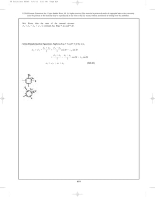


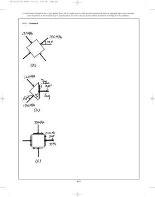
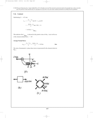
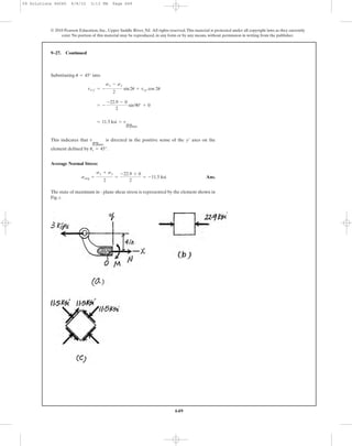
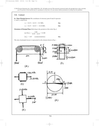
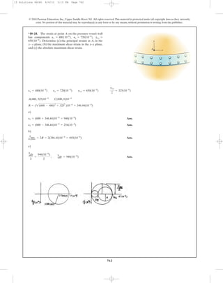
![In accordance to the established sign convention,
Ans.
Substitute into Eq. 9-1,
Thus,
Ans.
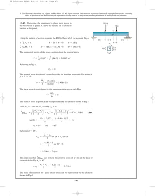
The element that represents the state of principal stress is shown in Fig. a.
Ans.
Ans.
By Inspection, has to act in the sense shown in Fig. b to maintain
equilibrium.
The element that represents the state of maximum in - plane shear stress is shown in
Fig. c.
savg =
sx + sy
2
=
-60 + (-80)
2
= -70 MPa
tmax
in-plane
uS = -5.65° and 84.3°
tan 2uS =
-(sx - sy)>2
txy
=
-[-60 - (-80)]>2
50
= -0.2
tmax
in-plane
=
C
a
sx - sy
2
b
2
+ txy
2
=
C
c
-60 - (-80)
2
d
2
+ 502
= 51.0 MPa
(uP)1 = 39.3° (uP)2 = -50.7°
= -19.0 MPa = s1
=
-60 + (-80)
2
+
-60 - (-80)
2
cos 78.69° + 50 sin 78.69°
sx¿ =
sx + sy
2
+
sx - sy
2
cos 2u + txy sin 2u
u = 39.34°
uP = 39.34° and -50.65°
tan 2uP =
txy
(sx - sy)>2
=
50
[-60 - (-80)]>2
= 5
s1 = -19.0 MPa s2 = -121 MPa
= -70 ; 22600
=
-60 + (-80)
2
;
C
c
-60 - (-80)
2
d
2
+ 502
s1, 2 =
sx + sy
2
;
C
a
sx - sy
2
b
2
+ txy
2
sx = -60 MPa sy = -80 MPa txy = 50 MPa
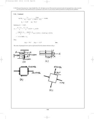
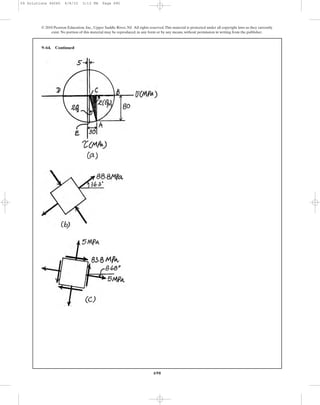
9–15. The state of stress at a point is shown on the element.
Determine (a) the principal stress and (b) the maximum
in-plane shear stress and average normal stress at the point.
Specify the orientation of the element in each case. Show
the results on each element.
630
© 2010 Pearson Education, Inc., Upper Saddle River, NJ. All rights reserved.This material is protected under all copyright laws as they currently
exist. No portion of this material may be reproduced, in any form or by any means, without permission in writing from the publisher.
80 MPa
60 MPa
50 MPa
09 Solutions 46060 6/8/10 3:13 PM Page 630](https://image.slidesharecdn.com/ch08-10combinedloadstransformations-190927203142/85/Ch08-10-combined-loads-transformations-100-320.jpg)


![640
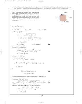
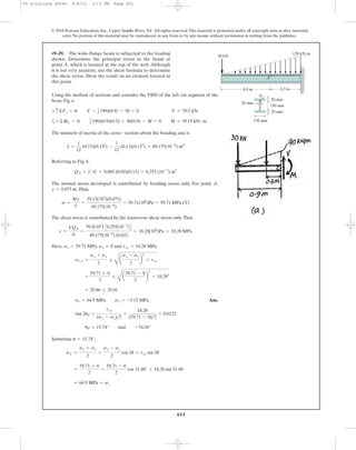
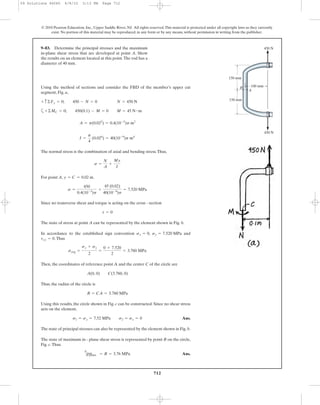
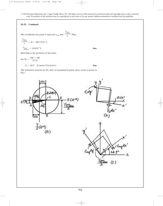
The location of the centroid c of the T cross-section, Fig. a, is
Referring to Fig. b,
Using the method of sections and considering the FBD of the left cut segment of the
beam, Fig. c,
a
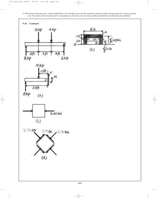
The normal stress developed is contributed by bending stress only. For point A,
.Thus
The shear stress is contributed by the transverse shear stress only.Thus,
The state of stress of point A can be represented by the element shown in Fig. c.
Here, , and .
Ans.s1 = 4.93 MPa s2 = -111 MPa
= -53.10 ; 58.02
=
-106.19 + 0
2
;
B
a
-106.19 - 0
2
b
2
+ 23.402
s1, 2 =
sx + sy
2
;
B
a
sx - sy
2
b
2
+ txy
2
txy = 23.40 MPasy = 0sx = -106.19 MPa
t =
VQA
It
=
100(103
)[0.17625(10-3
)]
37.6667(10-6
) (0.02)
= 23.40(106
)Pa = 23.40 MPa
s =
My
I
=
50(103
) (0.08)
37.6667(10-6
)
= 106 MPa
y = 0.155 - 0.075 = 0.08 m
+©MC = 0; 100(1)(0.5) - M = 0 M = 50 kN # m
+ c ©Fy = 0; V - 100(1) = 0 V = 100 kN
QA = y¿A¿ = 0.1175(0.075)(0.02) = 0.17625(10-3
) m3
= 37.6667(10-6
) m4
+
1
12
(0.2)(0.023
) + 0.2(0.02)(0.21 - 0.155)2
I =
1
12
(0.02)(0.23
) + 0.02(0.2)(0.155 - 0.1)2
y =
©y
'
A
©A
=
0.1(0.2)(0.02) + 0.21(0.02)(0.2)
0.2(0.02) + 0.02(0.2)
= 0.155 m
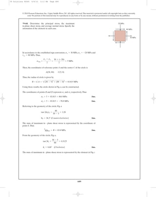
9–22. The T-beam is subjected to the distributed loading
that is applied along its centerline. Determine the principal
stress at point A and show the results on an element located
at this point.
© 2010 Pearson Education, Inc., Upper Saddle River, NJ. All rights reserved.This material is protected under all copyright laws as they currently
exist. No portion of this material may be reproduced, in any form or by any means, without permission in writing from the publisher.
0.5 m1 m
A
200 mm
200 mm
20 mm
20 mm
100 kN/m
A
75 mm
09 Solutions 46060 6/8/10 3:13 PM Page 640](https://image.slidesharecdn.com/ch08-10combinedloadstransformations-190927203142/85/Ch08-10-combined-loads-transformations-110-320.jpg)


![659
© 2010 Pearson Education, Inc., Upper Saddle River, NJ. All rights reserved.This material is protected under all copyright laws as they currently
exist. No portion of this material may be reproduced, in any form or by any means, without permission in writing from the publisher.
9–33. Continued
Orientation of Principal Plane: Applying Eq. 9-4 for point B.
Subsututing the results into Eq. 9-1 with yields
Hence,
Ans.up1 = -45.0° up2 = 45.0°
= 24.0 MPa = s1
= 0 + 0 + [-24.0 sin (-90.0°)]
sx¿ =
sx + sy
2
+
sx - sy
2
cos 2u + txy sin 2u
u = -45.0°
up = -45.0° and 45.0°
tan 2up =
txy
Asx - syB>2
=
-24.0
0
= - q
09 Solutions 46060 6/8/10 3:13 PM Page 659](https://image.slidesharecdn.com/ch08-10combinedloadstransformations-190927203142/85/Ch08-10-combined-loads-transformations-129-320.jpg)


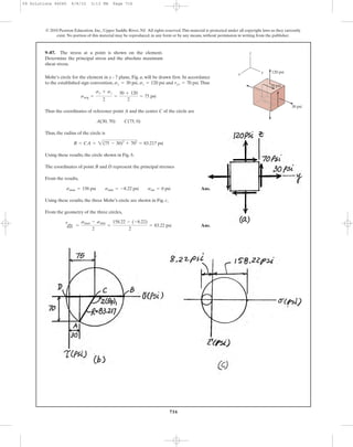
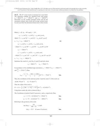
![Internal Loadings: Considering the equilibrium of the free - body diagram of the
hanger’s left cut segment, Fig. a,
a
Section Properties: The cross - sectional area and the moment of inertia about the
centroidal axis of the hanger’s cross section are
Referring to Fig. b,
Normal and Shear Stress: The normal stress is a combination of axial and bending
stresses.Thus,
The shear stress is caused by the transverse shear stress.
The state of stress at point A is represented by the element shown in Fig. c.
Construction of the Circle: , , and .Thus,
The coordinates of reference points A and the center C of the circle are
Thus, the radius of the circle is
Using these results, the circle is shown in Fig. d.
R = CA = 2(9.074 - 4.537)2
+ 0.97822
= 4.641 MPa
A(9.074, 0.9782) C(4.537, 0)
savg =
sx + sy
2
=
9.074 + 0
2
= 4.537 MPa
txy = 0.9782 MPasy = 0sx = 9.074 MPa
tA =
VQA
It
=
900C18.875A10-6
B D
1.7367A10-6
B(0.01)
= 0.9782 MPa
sA =
N
A
+
MyA
I
= -
900
1.4A10-3
B
+
675(0.025)
1.7367A10-6
B
= 9.074 MPa
= 18.875A10-6
B m3
QA = 2y1
œ
A1
œ
+ y2
œ
A2
œ
= 2[0.0375(0.025)(0.005)] + 0.0475(0.005)(0.04)
I =
1
12
(0.05)A0.13
B -
1
12
(0.04)A0.093
B = 1.7367A10-6
Bm4
A = 0.05(0.1) - 0.04(0.09) = 1.4A10-3
Bm2
M = 675N # m900(1) - 900(0.25) - M = 0+©MO = 0;
V = 900NV - 900 = 0+ c ©Fy = 0;
N = 900N900 - N = 0:+ ©Fx = 0;
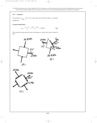
•9–81. Determine the principal stress at point A on the
cross section of the hanger at section a–a. Specify the
orientation of this state of stress and indicate the result on
an element at the point.
708
© 2010 Pearson Education, Inc., Upper Saddle River, NJ. All rights reserved.This material is protected under all copyright laws as they currently
exist. No portion of this material may be reproduced, in any form or by any means, without permission in writing from the publisher.
a b
ba
0.75 m 0.75 m
250 mm250 mm
0.5 m
900 N900 N
50 mm
25 mm
100 mm
5 mm
5 mm
5 mm
Sections a – a
and b – b
A
09 Solutions 46060 6/8/10 3:13 PM Page 708](https://image.slidesharecdn.com/ch08-10combinedloadstransformations-190927203142/85/Ch08-10-combined-loads-transformations-178-320.jpg)

![710
© 2010 Pearson Education, Inc., Upper Saddle River, NJ. All rights reserved.This material is protected under all copyright laws as they currently
exist. No portion of this material may be reproduced, in any form or by any means, without permission in writing from the publisher.
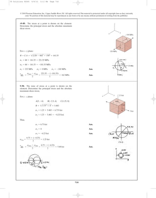
Internal Loadings: Considering the equilibrium of the free - body diagram of the
hanger’s left cut segment, Fig. a,
a
Section Properties: The cross - sectional area and the moment of inertia about the
centroidal axis of the hanger’s cross section are
Referring to Fig. b.
Normal and Shear Stress: The normal stress is contributed by the bending stress
only.
The shear stress is contributed by the transverse shear stress only.
The state stress at point A is represented by the element shown in Fig. c.
Construction of the Circle: , , and .Thus,
The coordinates of reference point A and the center C of the circle are
Thus, the radius of the circle is
Using these results, the cricle is shown in Fig. d.
R = CA = 2(32.39 - 16.19)2
+ 1.9562
= 16.313 MPa
A(32.39, 1.956) C(16.19, 0)
savg =
sx + sy
2
=
32.39 + 0
2
= 16.19 MPa
txy = 1.956 MPasy = 0sx = 32.39 MPa
tA =
VQA
It
=
1800C18.875A10-6
B D
1.7367A10-6
B(0.01)
= 1.956 MPa
sA =
MyA
I
=
2250(0.025)
1.7367A10-6
B
= 32.39 MPa
= 18.875A10-6
B m3
QA = 2y1
œ
A1
œ
+ y2
œ
A2
œ
= 2[0.0375(0.025)(0.005)] + 0.0475(0.005)(0.04)
I =
1
12
(0.05)A0.13
B -
1
12
(0.04)A0.093
B = 1.7367A10-6
Bm4
A = 0.05(0.1) - 0.04(0.09) = 1.4A10-3
Bm2
+©MO = 0; 900(2.25) + 900(0.25) - M = 0 M = 2250N # m
+ c©Fy = 0; V - 900 - 900 = 0 V = 1800N
9–82. Determine the principal stress at point A on the
cross section of the hanger at section b–b. Specify the
orientation of the state of stress and indicate the results on
an element at the point.
a b
ba
0.75 m 0.75 m
250 mm250 mm
0.5 m
900 N900 N
50 mm
25 mm
100 mm
5 mm
5 mm
5 mm
Sections a – a
and b – b
A
09 Solutions 46060 6/8/10 3:13 PM Page 710](https://image.slidesharecdn.com/ch08-10combinedloadstransformations-190927203142/85/Ch08-10-combined-loads-transformations-180-320.jpg)


![717
© 2010 Pearson Education, Inc., Upper Saddle River, NJ. All rights reserved.This material is protected under all copyright laws as they currently
exist. No portion of this material may be reproduced, in any form or by any means, without permission in writing from the publisher.
Mohr’s circle for the element in x - z plane, Fig. a, will be drawn first. In accordance
to the established sign convention, , and .Thus
Thus, the coordinates of reference point A and the center C of the circle are
Thus, the radius of the circle is
Using these results, the circle in shown in Fig. b,
The coordinates of points B and D represent and , respectively.
From the results obtained,
Ans.
Using these results, the three Mohr’s circles are shown in Fig, c.
From the geometry of the cricle,
Ans.
tabs
max =
smax - smin
2
=
7.06 - (-9.06)
2
= 8.06 ksi
sint = 0 ksi smax = 7.06 ksi smin = -9.06 ksi
smin = -9.06 ksi
sint = 0
smax = 7.06 ksi
s = -1 + 265 = 7.062 ksi
s2s1
R = CA = 2[-2 - (-1)]2
+ 82
= 265 ksi
A(-2, 8) C(-1, 0)
savg =
sx + sz
2
=
-2 + 0
2
= -1 ksi
txz = 8 ksisz = 0sx = -2 ksi
*9–88. The stress at a point is shown on the element.
Determine the principal stress and the absolute maximum
shear stress.
z
yx
2 ksi
8 ksi
09 Solutions 46060 6/8/10 3:13 PM Page 717](https://image.slidesharecdn.com/ch08-10combinedloadstransformations-190927203142/85/Ch08-10-combined-loads-transformations-187-320.jpg)


![722
© 2010 Pearson Education, Inc., Upper Saddle River, NJ. All rights reserved.This material is protected under all copyright laws as they currently
exist. No portion of this material may be reproduced, in any form or by any means, without permission in writing from the publisher.
Internal Loadings: Considering the equilibrium of the free - body diagram of the
bracket’s upper cut segment, Fig. a,
Section Properties: The cross - sectional area and the moment of inertia of the
bracket’s cross section are
Referring to Fig. b.
Normal and Shear Stress: The normal stress is
The shear stress is contributed by the transverse shear stress.
The state of stress at point A is represented by the element shown in Fig. c.
Construction of the Circle: , , and .Thus,
The coordinates of reference point A and the center C of the circle are
Thus, the radius of the circle is
R = CA = 2[0 - (-171.43)]2
+ 734.852
= 754.58 psi
A(0, 734.85) C(-171.43, 0)
savg =
sx + sy
2
=
0 + (-342.86)
2
= -171.43 psi
txy = 734.85sy = -342.86 psisx = 0
tA =
VQA
It
=
400(0.3672)
0.79948(0.25)
= 734.85 psi
sA =
N
A
= -
300
0.875
= -342.86 psi
QA = x1
œ
A1
œ
+ x2
œ
A2
œ
= 0.625(1.25)(0.25) + 1.375(0.25)(0.5) = 0.3672 in3
I =
1
12
(0.5)A33
B -
1
12
(0.25)A2.53
B = 0.79948 in4
A = 0.5(3) - 0.25(2.5) = 0.875 in2
©MO = 0; M - 500a
3
5
b(12) - 500a
4
5
b(6) = 0 M = 6000 lb # in
;+ ©Fx = 0; V - 500a
4
5
b = 0 V = 400 lb
+ c ©Fy = 0; N - 500a
3
5
b = 0 N = 300 lb
9–94. Determine the principal stress and absolute
maximum shear stress developed at point A on the cross
section of the bracket at section a–a.
6 in.
12 in.
500 lb
1.5 in.1.5 in.
0.25 in.0.25 in.
0.5 in. 0.25 in.
aa
3
4
5
A
B
Section a – a
09 Solutions 46060 6/8/10 3:13 PM Page 722](https://image.slidesharecdn.com/ch08-10combinedloadstransformations-190927203142/85/Ch08-10-combined-loads-transformations-192-320.jpg)


![733
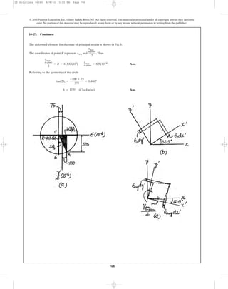
Internal Loadings: Considering the equilibrium of the free - body diagram of the
propeller shaft’s right segment, Fig. a,
Section Properties: The cross - sectional area and the polar moment of inertia of the
propeller shaft’s cross section are
Normal and Shear Stress: The normal stress is a contributed by axial stress only.
The shear stress is contributed by the torsional shear stress only.
The state of stress at point A is represented by the element shown in Fig. b.
Construction of the Circle: , , and
Thus,
The coordinates of reference point A and the center C of the circle are
Thus, the radius of the circle is
Using these results, the circle is shown is Fig. c.
In - Plane Principal Stress: The coordinates of reference points B and D represent
and , respectively.
Ans.
Ans.s2 = -0.5093 - 3.795 = -4.30 MPa
s1 = -0.5093 + 3.795 = 3.29 MPa
s2s1
R = CA = 2[-1.019 - (-0.5093)]2
+ (-3.761)2
= 3.795 MPa
A(-1.019, -3.761) C(-0.5093, 0)
savg =
sx + sy
2
=
-1.019 + 0
2
= -0.5093 MPa
txy = -3.761 MPa.sy = 0sx = -1.019 MPa
tA =
Tc
J
=
2A103
B(0.075)
12.6953125pA10-6
B
= 3.761 MPa
sA =
N
A
= -
10A103
B
3.125pA10-3
B
= -1.019 MPa
J =
p
2
A0.0754
- 0.054
B = 12.6953125pA10-6
B m4
A = pA0.0752
- 0.052
B = 3.125pA10-3
B m2
©Mx = 0; T - 2 = 0 T = 2 kN # m
©Fx = 0; 10 - N = 0 N = 10 kN
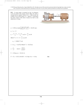
9–103. The propeller shaft of the tugboat is subjected to
the compressive force and torque shown. If the shaft has an
inner diameter of 100 mm and an outer diameter of 150 mm,
determine the principal stress at a point A located on the
outer surface.
© 2010 Pearson Education, Inc., Upper Saddle River, NJ. All rights reserved.This material is protected under all copyright laws as they currently
exist. No portion of this material may be reproduced, in any form or by any means, without permission in writing from the publisher.
A
2 kN·m
10 kN
09 Solutions 46060 6/8/10 3:13 PM Page 733](https://image.slidesharecdn.com/ch08-10combinedloadstransformations-190927203142/85/Ch08-10-combined-loads-transformations-203-320.jpg)


![741
© 2010 Pearson Education, Inc., Upper Saddle River, NJ. All rights reserved.This material is protected under all copyright laws as they currently
exist. No portion of this material may be reproduced, in any form or by any means, without permission in writing from the publisher.
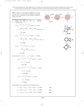
a)
Ans.
Orientation of and
and
Use Eq. 10.5 to determine the direction of and
Therefore Ans.
b)
Ans.
Ans.
Orientation of
Ans.
Use Eq. 10–6 to determine the sign of
gx¿y¿ = 2c -
120 - (-180)
2
sin (-63.4°) +
150
2
cos (-63.4°)d10-6
= 335(10-6
)
u = us = -31.7°
gx¿y¿
2
= -
ex - ey
2
sin 2u +
gxy
2
cos 2u
gmax
in-plane
us = -31.7° and 58.3°
tan 2us =
-(ex - ey)
gxy
=
-[120 - (-180)]
150
= -2.0
gmax
eavg =
ex + ey
2
= c
120 + (-180)
2
d 10-6
= -30.0(10-6
)
gmax
in-plane
= 2c
A
a
120 - (-180)
2
b
2
+ a
150
2
b
2
d10-6
= 335 (10-6
)
gmax
in-plane
2
=
A
a
ex - ey
2
b
2
+ a
gxy
2
b
2
up1
= 13.3° ; up2
= -76.7°
= 138 (10-6
) = e1
ex¿ = c
120 + (-180)
2
+
120 - (-180)
2
cos (26.56°) +
150
2
sin 26.56°d 10-6
u = up = 13.28°
ex¿ =
ex + ey
2
+
ex - ey
2
cos 2u +
gxy
2
sin 2u
e2e1
-76.72°up = 13.28°
tan 2up =
gxy
ex - ey
=
150
[120 - (-180)]
= 0.5
e2e1
e1 = 138(10-6
); e2 = -198(10-6
)
= c
120 + (-180)
2
;
A
a
120 - (-180)
2
b
2
+ a
150
2
b
2
d 10-6
e1, 2 =
ex + ey
2
;
A
a
Ex - Ey
2
b
2
+ a
gxy
2
b
2
ex = 120(10-6
) ey = -180(10-6
) gxy = 150(10-6
)
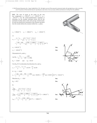
*10–4. The state of strain at a point on a wrench
has components
Use the strain-transformation equations to
determine (a) the in-plane principal strains and (b) the
maximum in-plane shear strain and average normal strain.
In each case specify the orientation of the element and show
how the strains deform the element within the x–y plane.
150110-6
2.
gxy =Py = -180110-6
2,Px = 120110-6
2,
10 Solutions 46060 6/8/10 3:15 PM Page 741](https://image.slidesharecdn.com/ch08-10combinedloadstransformations-190927203142/85/Ch08-10-combined-loads-transformations-211-320.jpg)


gx¿y¿
2
= -
ex - ey
2
sin 2u +
gxy
2
cos 2u
= -541(10-6
)
= c
-200 + (-650)
2
-
-200 - (-650)
2
cos (40°) -
(-175)
2
sin (40°)d(10-6
)
ey¿ =
ex + ey
2
-
ex - ey
2
cos 2u -
gxy
2
sin 2u
= -309(10-6
)
= c
-200 + (-650)
2
+
(-200) - (-650)
2
cos (40°) +
(-175)
2
sin (40°)d(10-6
)
ex¿ =
ex + ey
2
+
ex - ey
2
cos 2u +
gxy
2
sin 2u
ex = -200(10-6
) ey = -650(10-6
) gxy = -175(10-6
) u = 20°
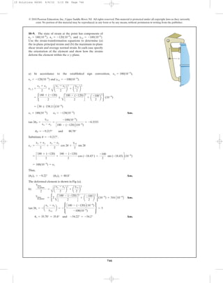
*10–8. The state of strain at the point on the bracket
has components ϭ
Use the strain-transformation equations to
determine the equivalent in-plane strains on an element
oriented at an angle of counterclockwise from the
original position. Sketch the deformed element due to these
strains within the x–y plane.
u = 20°
-175110-6
2.
gxyPy = -650110-6
2,Px = -200110-6
2,
y
x
10 Solutions 46060 6/8/10 3:15 PM Page 745](https://image.slidesharecdn.com/ch08-10combinedloadstransformations-190927203142/85/Ch08-10-combined-loads-transformations-215-320.jpg)

 = 718(10-6
)
gx¿y¿
2
= -
ex - ey
2
sin 2u +
gxy
2
cos 2u
= 46.7(10-6
)
= c
400 + (-250)
2
-
400 - (-250)
2
cos (60°) -
310
2
sin (-60°)d(10-6
)
ey¿ =
ex + ey
2
-
ex - ey
2
cos 2u -
gxy
2
sin 2u
= 103(10-6
)
= c
400 + (-250)
2
+
400 - (-250)
2
cos (-60°) + a
310
2
b sin (-60°)d(10-6
)
ex¿ =
ex + ey
2
+
ex - ey
2
cos 2u +
gxy
2
sin 2u
ex = 400(10-6
) ey = -250(10-6
) gxy = 310(10-6
) u = -30°
10 Solutions 46060 6/8/10 3:15 PM Page 748](https://image.slidesharecdn.com/ch08-10combinedloadstransformations-190927203142/85/Ch08-10-combined-loads-transformations-218-320.jpg)

![750
© 2010 Pearson Education, Inc., Upper Saddle River, NJ. All rights reserved.This material is protected under all copyright laws as they currently
exist. No portion of this material may be reproduced, in any form or by any means, without permission in writing from the publisher.
10–11. Continued
Strain Transformation Equations:
We obtain
Ans.
Ans.
Ans.
The deformed element for this state of strain is shown in Fig. a.
= 300A10-6
B
= c
500 + 300
2
-
500 - 300
2
cos (-90°) - a
-200
2
b sin (-90°)d A10-6
B
ey¿ =
ex + ey
2
-
ex - ey
2
cos 2u -
gxy
2
sin 2u
= 200A10-6
B
gx¿y¿ = [-(500 - 300) sin (-90°) + (-200) cos (-90°)]A10-6
B
gx¿y¿
2
= - a
ex - ey
2
b sin 2u +
gxy
2
cos 2u
= 500A10-6
B
= c
500 + 300
2
+
500 - 300
2
cos (-90°) + a
-200
2
b sin (-90°)d A10-6
B
ex¿ =
ex + ey
2
+
ex - ey
2
cos 2u +
gxy
2
sin 2u
ex = 500A10-6
B ey = 300A10-6
B gxy = -200A10-6
B u = -45°
*10–12. The state of plane strain on an element is given by
and
Determine the equivalent state of strain on an element at
the same point oriented 45° clockwise with respect to the
original element.
gxy = -200110-6
2.Py = 300110-6
2,Px = 500110-6
2,
y
x
dx
dy
Pydy
Pxdx
gxy
2
gxy
2
10 Solutions 46060 6/8/10 3:15 PM Page 750](https://image.slidesharecdn.com/ch08-10combinedloadstransformations-190927203142/85/Ch08-10-combined-loads-transformations-220-320.jpg)

![752
© 2010 Pearson Education, Inc., Upper Saddle River, NJ. All rights reserved.This material is protected under all copyright laws as they currently
exist. No portion of this material may be reproduced, in any form or by any means, without permission in writing from the publisher.
The algebraic sign for when can be obtained using
Average Normal Strain:
Ans.
The deformed element for this state of strain is shown in Fig. b.
eavg =
ex + ey
2
= a
-300 + 0
2
b A10-6
B = -150A10-6
B
= 335A10-6
B
gx¿y¿ = [-(-300 - 0) sin 63.43° + 150 cos 63.43°]A10-6
B
gx¿y¿
2
= - ¢
ex - ey
2
≤ sin 2u +
gxy
2
cos 2u
u = us = 31.7°
gmax
in-plane
10–13. Continued
10 Solutions 46060 6/8/10 3:15 PM Page 752](https://image.slidesharecdn.com/ch08-10combinedloadstransformations-190927203142/85/Ch08-10-combined-loads-transformations-222-320.jpg)

![754
© 2010 Pearson Education, Inc., Upper Saddle River, NJ. All rights reserved.This material is protected under all copyright laws as they currently
exist. No portion of this material may be reproduced, in any form or by any means, without permission in writing from the publisher.
Orientation of the Maximum In-Plane Shear Strain: Applying Eq. 10–10,
Ans.
The proper sign of can be determined by substituting into Eq.10–6.
Normal Strain and Shear strain: In accordance with the sign convention,
Average Normal Strain: Applying Eq. 10–12,
Ans.eavg =
ex + ey
2
= c
250 + 300
2
d A10-6
B = 275A10-6
B
ex = 250A10-6
B ey = 300A10-6
B gxy = -180A10-6
B
= -187A10-6
B
gx¿y¿ = {-[250 - 300] sin (-15.52°) + (-180) cos (-15.52°)}A10-6
B
gx¿y¿
2
= -
ex - ey
2
sin 2u +
gxy
2
cos 2u
u = -7.76°
g max
in-plane
us = -7.76° and 82.2°
tan 2us = -
ex - ey
gxy
= -
250 - 300
-180
= -0.2778
10–14. Continued
10 Solutions 46060 6/8/10 3:15 PM Page 754](https://image.slidesharecdn.com/ch08-10combinedloadstransformations-190927203142/85/Ch08-10-combined-loads-transformations-224-320.jpg)

![756
© 2010 Pearson Education, Inc., Upper Saddle River, NJ. All rights reserved.This material is protected under all copyright laws as they currently
exist. No portion of this material may be reproduced, in any form or by any means, without permission in writing from the publisher.
Ans.
Ans.
Ans.tan 2uP = a
75
30 + 120
b, uP = 13.3°
e2 = (-30 - 167.71)(10-6
) = -198(10-6
)
e1 = (-30 + 167.71)(10-6
) = 138(10-6
)
= 167.71 (10-6
)
R = C 2[120 - (-30)]2
+ (75)2
D(10-6
)
A (120, 75)(10-6
) C (-30, 0)(10-6
)
ex = 120(10-6
) ey = -180(10-6
) gxy = 150(10-6
)
•10–17. Solve part (a) of Prob. 10–4 using Mohr’s circle.
10 Solutions 46060 6/8/10 3:15 PM Page 756](https://image.slidesharecdn.com/ch08-10combinedloadstransformations-190927203142/85/Ch08-10-combined-loads-transformations-226-320.jpg)
![757
© 2010 Pearson Education, Inc., Upper Saddle River, NJ. All rights reserved.This material is protected under all copyright laws as they currently
exist. No portion of this material may be reproduced, in any form or by any means, without permission in writing from the publisher.
Ans.
Ans.
Ans.tan 2us =
120 + 30
75
us = -31.7°
eavg = -30 (10-6
)
gxy max
in-plane
= 335(10-6
)
gxy
2 max
in-plane
= R = 167.7(10-6
)
= 167.71 (10-6
)
R = C 2[120 - (-30)]2
+ (75)2
D(10-6
)
A (120, 75)(10-6
) C (-30, 0)(10-6
)
ex = 120(10-6
) ey = -180(10-6
) gxy = 150(10-6
)
10–18. Solve part (b) of Prob. 10–4 using Mohr’s circle.
10 Solutions 46060 6/8/10 3:15 PM Page 757](https://image.slidesharecdn.com/ch08-10combinedloadstransformations-190927203142/85/Ch08-10-combined-loads-transformations-227-320.jpg)
 = 241.41(10-6
)
A(-200, -87.5)(10-6
) C(-425, 0)(10-6
)
u = 20°, 2u = 40°
ex = -200(10-6
) ey = -650(10-6
) gxy = -175(10-6
)
gxy
2
= -87.5(10-6
)
10 Solutions 46060 6/8/10 3:15 PM Page 758](https://image.slidesharecdn.com/ch08-10combinedloadstransformations-190927203142/85/Ch08-10-combined-loads-transformations-228-320.jpg)
 = 360.1(10-6
)
A(400, 155)(10-6
) C(75, 0)(10-6
)
ex = 400(10-6
) ey = -250(10-6
) gxy = 310(10-6
)
gxy
2
= 155(10-6
) u = 30°
*10–20. Solve Prob. 10–10 using Mohr’s circle.
10 Solutions 46060 6/8/10 3:15 PM Page 759](https://image.slidesharecdn.com/ch08-10combinedloadstransformations-190927203142/85/Ch08-10-combined-loads-transformations-229-320.jpg)


![769
© 2010 Pearson Education, Inc., Upper Saddle River, NJ. All rights reserved.This material is protected under all copyright laws as they currently
exist. No portion of this material may be reproduced, in any form or by any means, without permission in writing from the publisher.
Applying Eq. 10–16,
ey = 480 (10-6
)
480 (10-6
) = ex cos2
(270°) + ey sin2
(270°) + gxy sin (270°) cos (270°)
ex = 650 (10-6
)
650(10-6
) = ex cos2
(180°) + ey sin2
(180°) + gxy sin (180°) cos (180°)
e = ex cos2
u + ey sin2
u + gxy sinucosu
ua = 180°; ub = 225° uc = 270°
ea = 650(10-6
); eb = -300(10-6
); ec = 480(10-6
)
*10–28. The strain rosette is mounted on the link of
the backhoe. The following readings are obtained from
each gauge:
Determine (a) the in-plane principal strains and (b) the
maximum in-plane shear strain and associated average
normal strain.
Pc = 480110-6
2.Pb = -300110-6
2,Pa = 650110-6
2,
45°
45Њ
a
b
c
45Њ
gxy = -1730 (10-6
)
-300 (10-6
) = 650 (10-6
) cos2
(225°) + 480 (10-6
) sin2
(225°) + gxy sin (225°) cos (225°)
Therefore,
Mohr’s circle:
(a) Ans.
Ans.
(b) Ans.
Ans.eavg = 565(10-6
)
gmax
in-plane
= 2 R = 2(869.17) (10-6
) = 1738 (10-6
)
e2 = [565 - 869.17]10-6
= -304 (10-6
)
e1 = [565 + 869.17]10-6
= 1434 (10-6
)
R = CA = C 2(650 - 565)2
+ 8652
D10-6
= 869.17 (10-6
)
A(650, -865) 10-6
C(565, 0) 10-6
gxy
2
= -865 (10-6
)
ex = 650 (10-6
) ey = 480 (10-6
) gxy = -1730 (10-6
)
10 Solutions 46060 6/8/10 3:15 PM Page 769](https://image.slidesharecdn.com/ch08-10combinedloadstransformations-190927203142/85/Ch08-10-combined-loads-transformations-239-320.jpg)
![770
© 2010 Pearson Education, Inc., Upper Saddle River, NJ. All rights reserved.This material is protected under all copyright laws as they currently
exist. No portion of this material may be reproduced, in any form or by any means, without permission in writing from the publisher.
Generalized Hooke’s Law: For plane stress, .Applying Eq. 10–18,
[1]
[2]
Adding Eq [1] and Eq.[2] yields.
(Q.E.D.)
Substituting into Eq. [2]
(Q.E.D.)=
E
1 - v2
(ex + v ey)
=
E v ex + E ey - E ey + Eey v2
v(1 - v2
)
sx =
E Av ex + eyB
v (1 - v2
)
-
Eey
v
E ey = -vsx +
E
1 - v2 Av ex + eyB
sy
sy =
E
1 - v2 Avex + eyB
vE ex - E ey = sy - v2
sy
Eey = -v sx + sy
ey =
1
E
(sy - v sx)
vEex = v sx - v2
sy
vEex = Asx - v syB v
ex =
1
E
Asx - vsyB
sz = 0
10–30. For the case of plane stress, show that Hooke’s law
can be written as
sx =
E
11 - n2
2
1Px + nPy2, sy =
E
11 - n2
2
1Py + nPx2
10 Solutions 46060 6/8/10 3:15 PM Page 770](https://image.slidesharecdn.com/ch08-10combinedloadstransformations-190927203142/85/Ch08-10-combined-loads-transformations-240-320.jpg)

![772
© 2010 Pearson Education, Inc., Upper Saddle River, NJ. All rights reserved.This material is protected under all copyright laws as they currently
exist. No portion of this material may be reproduced, in any form or by any means, without permission in writing from the publisher.
From Eq. (6).
(13)
Substitute Eqs. (13), (6) and (9) into Eq. (2),
QED
gx¿y¿
2
= -
(ex - ey)
2
sin 2u +
gxy
2
cos 2u
E
2 (1 + v)
gx¿y¿ = -
E (ex - ey)
2 (1 + v)
sin 2u +
E
2 (1 + v)
gxy cos 2u
gx¿y¿ = G gx¿y¿ =
E
2 (1 + v)
gx¿y¿
10–31. Continued
Ans.
Ans.ecu =
1 - 2v
E
(sx + sy + sz) =
1 - 2(0.35)
14.9(103
)
(14 + 0 + 0) = 0.282(10-3
)
Ecu = 14.9(103
) ksi
940(10-6
) =
1
Ecu
[14(103
) - 0.35(0 + 0)]
ex =
1
E
[sx - v(sy + sz)]
*10–32. A bar of copper alloy is loaded in a tension
machine and it is determined that and
Determine the modulus of
elasticity, and the dilatation, of the copper.
ncu = 0.35.
ecu,Ecu,
sz = 0.sy = 0,sx = 14 ksi,
Px = 940110-6
2
Plane stress,
See Prob 10-30,
Ans.
Ans.=
10(103
)
1 - 0.332
(400(10-6
) + 0.33(780)(10-6
)) = 7.38 ksi
s2 =
E
1 - v2
(e2 + ve1)
=
10(103
)
1 - 0.332
(780(10-6
) + 0.33(400)(10-6
)) = 10.2 ksi
s1 =
E
1 - v2
(e1 + ve2)
s3 = 0
•10–33. The principal strains at a point on the aluminum
fuselage of a jet aircraft are and
Determine the associated principal stresses at
the point in the same plane.
Hint: See Prob. 10–30.
nal = 0.33.Eal = 101103
2 ksi,
400110-6
2.
P2 =P1 = 780110-6
2
10 Solutions 46060 6/8/10 3:15 PM Page 772](https://image.slidesharecdn.com/ch08-10combinedloadstransformations-190927203142/85/Ch08-10-combined-loads-transformations-242-320.jpg)
![773
© 2010 Pearson Education, Inc., Upper Saddle River, NJ. All rights reserved.This material is protected under all copyright laws as they currently
exist. No portion of this material may be reproduced, in any form or by any means, without permission in writing from the publisher.
Normal Stress: For uniaxial loading, .
Normal Strain: Applying the generalized Hooke’s Law.
Therefore.
Absolute Maximum Shear Strain:
Ans.= [30.48 - (-10.67)]A10-6
B = 41.1A10-6
B
gabs
max = emax - emin
emax = 30.48A10-6
B emin = -10.67A10-6
B
= -10.67A10-6
B
=
1
73.1(109
)
C0 - 0.35A2.228A106
B + 0B D
ez =
1
E
Csz - vAsx + syB D
= -10.67A10-6
B
=
1
73.1(109
)
C0 - 0.35A2.228A106
B + 0B D
ey =
1
E
Csy - v(sx + sz)D
= 30.48A10-6
B
=
1
73.1(109
)
C2.228A106
B - 0D
ex =
1
E
Csx - vAsy + szB D
sx =
P
A
=
700
p
4 (0.022
)
= 2.228 MPa
sy = sz = 0
10–34. The rod is made of aluminum 2014-T6. If it is
subjected to the tensile load of 700 N and has a diameter of
20 mm, determine the absolute maximum shear strain in the
rod at a point on its surface.
700 N700 N
10 Solutions 46060 6/8/10 3:15 PM Page 773](https://image.slidesharecdn.com/ch08-10combinedloadstransformations-190927203142/85/Ch08-10-combined-loads-transformations-243-320.jpg)

![775
© 2010 Pearson Education, Inc., Upper Saddle River, NJ. All rights reserved.This material is protected under all copyright laws as they currently
exist. No portion of this material may be reproduced, in any form or by any means, without permission in writing from the publisher.
Pure shear
Ans.
Ans.
Also,
Ans.T =
tJ
c
=
12.308(106
)A
p
2
B(0.015)4
0.015
= 65.2 N # m
t = Gg = 76.923(109
)(160)(10-6
) = 12.308(106
) Pa
G =
E
2(1 + V)
=
200(109
)
2(1 + 0.3)
= 76.923(109
)
gxy = -160(10-6
)
80(10-6
) = 0 + 0 + g sin 135° cos 135°
u = 135°
gxy = -160(10-6
)
-80(10-6
) = 0 + 0 + gxy sin 45° cos 45°
u = 45°
ex¿ = ex cos2
u + ey sin2
u + gxy sin u cos u
ex = ey = 0
ex¿ = -80(10-6
) ey¿ = 80(10-6
)
*10–36. The steel shaft has a radius of 15 mm. Determine
the torque T in the shaft if the two strain gauges, attached to
the surface of the shaft, report strains of
and Also, compute the strains acting in the x
and y directions. nst = 0.3.Est = 200 GPa,
Py¿ = 80110-6
2.
Px¿ = -80110-6
2
45Њ
y
x
x¿y¿
T
T
a) For rubber:
Ans.
b) For glass:
Ans.Kg =
Eg
3 (1 - 2 vg)
=
8(103
)
3[1 - 2(0.24)]
= 5.13 (103
) ksi
Kr =
Er
3 (1 - 2 vr)
=
0.4
3[1 - 2(0.48)]
= 3.33 ksi
10–37. Determine the bulk modulus for each of the
following materials: (a) rubber, and
(b) glass, ng = 0.24.Eg = 81103
2 ksi,
nr = 0.48,Er = 0.4 ksi,
10 Solutions 46060 6/8/10 3:15 PM Page 775](https://image.slidesharecdn.com/ch08-10combinedloadstransformations-190927203142/85/Ch08-10-combined-loads-transformations-245-320.jpg)
![776
© 2010 Pearson Education, Inc., Upper Saddle River, NJ. All rights reserved.This material is protected under all copyright laws as they currently
exist. No portion of this material may be reproduced, in any form or by any means, without permission in writing from the publisher.
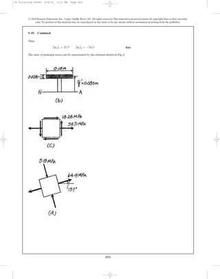
Ans.emax = 546 (10-6
) eint = 346 (10-6
) emin = -910 (10-6
)
e3 =
1
E
Cs3 - v(s1 + s2)D =
1
29.0(103
)
C -20 - 0.32(12 + 8)D = -910 (10-6
)
e2 =
1
E
Cs2 - v(s1 + s3)D =
1
29.0(103
)
e8 - 0.32C12 + (-20)D f = 364 (10-6
)
e1 =
1
E
Cs1 - v(s2 + s3)D =
1
29.0(103
)
e12 - 0.32C8 + (-20)D f = 546 (10-6
)
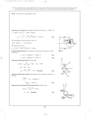
10–38. The principal stresses at a point are shown in the
figure. If the material is A-36 steel, determine the
principal strains.
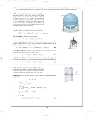
Normal Stresses: Since , the thin wall analysis is valid to
determine the normal stress in the wall of the spherical vessel. This is a plane stress
problem where since there is no load acting on the outer surface of the wall.
[1]
Normal Strains: Applying the generalized Hooke’s Law with
Ans.
From Eq.[1]
Maximum In-Plane Shear (Sphere’s Surface): Mohr’s circle is simply a dot. As the
result, the state of stress is the same consisting of two normal stresses with zero
shear stress regardless of the orientation of the element.
Ans.
Absolute Maximum Shear Stress:
Ans.
tabs
max =
smax - smin
2
=
171.43 - 0
2
= 85.7MPa
t max
in-plane = 0
smax = slat = 50.0(3.4286) = 171.43 MPa
p = 3.4286 MPa = 3.43 MPa
0.600A10-3
B =
1
200(104
)
[50.0p - 0.3(50.0p + 0)]
emax =
1
E
Csmax - V (slat + smin)D
emax = elat =
0.012
20
= 0.600A10-3
B mm>mm
smax = slat =
pr
2t
=
p(1000)
2(10)
= 50.0p
smin = 0
r
t
=
1000
10
= 100 7 10
10–39. The spherical pressure vessel has an inner
diameter of 2 m and a thickness of 10 mm. A strain gauge
having a length of 20 mm is attached to it, and it is observed
to increase in length by 0.012 mm when the vessel
is pressurized. Determine the pressure causing this
deformation, and find the maximum in-plane shear stress,
and the absolute maximum shear stress at a point on the
outer surface of the vessel. The material is steel, for which
and nst = 0.3.Est = 200 GPa
12 ksi
20 ksi
8 ksi
20 mm
10 Solutions 46060 6/8/10 3:15 PM Page 776](https://image.slidesharecdn.com/ch08-10combinedloadstransformations-190927203142/85/Ch08-10-combined-loads-transformations-246-320.jpg)


![781
© 2010 Pearson Education, Inc., Upper Saddle River, NJ. All rights reserved.This material is protected under all copyright laws as they currently
exist. No portion of this material may be reproduced, in any form or by any means, without permission in writing from the publisher.
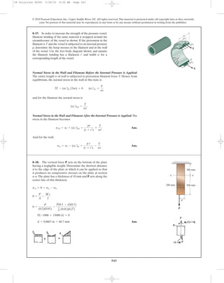
For cylindrical vessel:
(1)
For hemispherical end caps:
(2)
Equate Eqs. (1) and (2):
QED
Ans.th =
(1 - v) tc
2 - v
=
(1 - 0.3) (0.5)
2 - 0.3
= 0.206 in.
tc
th
=
2 (1 - 1
2 v)
1 - v
=
2 - v
1 - v
p r2
E tc
a1 -
1
2
vb =
p r2
2 E th
(1 - v)
d r = e1 r =
p r2
2 E th
(1 - v)
=
1
E
a
p r
2 th
-
v p r
2 th
b =
p r
2 E th
(1 - v)
e1 =
1
E
[s1 - v (s2 + s3)] ; s3 = 0
s1 = s2 =
p r
2 th
d r = e1 r =
p r2
E tc
a1 -
1
2
vb
=
1
E
a
p r
tc
-
v p r
2 tc
b =
p r
E tc
a1 -
1
2
vb
e1 =
1
E
[s1 - v (s2 + s3)] s3 = 0
s1 =
p r
tc
; s2 =
p r
2 tc
10–45. The cylindrical pressure vessel is fabricated using
hemispherical end caps in order to reduce the bending stress
that would occur if flat ends were used.The bending stresses
at the seam where the caps are attached can be eliminated
by proper choice of the thickness and of the caps and
cylinder, respectively. This requires the radial expansion to
be the same for both the hemispheres and cylinder. Show
that this ratio is Assume that the
vessel is made of the same material and both the cylinder
and hemispheres have the same inner radius. If the cylinder
is to have a thickness of 0.5 in.,what is the required thickness
of the hemispheres? Take n = 0.3.
tc>th = 12 - n2>11 - n2.
tcth
tc
th
r
10 Solutions 46060 6/8/10 3:15 PM Page 781](https://image.slidesharecdn.com/ch08-10combinedloadstransformations-190927203142/85/Ch08-10-combined-loads-transformations-251-320.jpg)
![782
© 2010 Pearson Education, Inc., Upper Saddle River, NJ. All rights reserved.This material is protected under all copyright laws as they currently
exist. No portion of this material may be reproduced, in any form or by any means, without permission in writing from the publisher.
Normal Stresses: For plane stress, .
Normal Strains: Applying the generalized Hooke’s Law.
[1]
[2]
Solving Eqs.[1] and [2] yields:
Ans.s1 = 8.37 ksi s2 = 6.26 ksi
3.50 = s2 - 0.33s1
350A10-6
B =
1
10(103
)
Cs2 - 0.33(s1 + 0)D
e2 =
1
E
Cs2 - v (s1 + s3)D
6.30 = s1 - 0.33s2
630A10-6
B =
1
10(103
)
[s1 - 0.33(s2 + 0)]
e1 =
1
E
Cs1 - v (s2 + s3)D
s3 = 0
10–46. The principal strains in a plane, measured
experimentally at a point on the aluminum fuselage of a jet
aircraft, are and If this is
a case of plane stress, determine the associated principal
stresses at the point in the same plane. ksi
and nal = 0.33.
Eal = 10(103
)
P2 = 350(10-6
).P1 = 630(10-6
)
Using these results,
e1 = 833(10-6
) e2 = 168(10-6
) e3 = -763(10-6
)
e3 =
1
E
Cs3 - v(s1 + s2)D =
1
10(103
)
C -4 - 0.33(8 + 3)D = -763 (10-6
)
e2 =
1
E
Cs2 - v(s1 + s3)D =
1
10(103
)
e3 - 0.33C8 + (-4)D f = 168 (10-6
)
e1 =
1
E
Cs1 - v(s2 + s3)D =
1
10(103
)
e8 - 0.33C3 + (-4)D f = 833 (10-6
)
10–47. The principal stresses at a point are shown in
the figure. If the material is aluminum for which
and determine the principal
strains.
nal = 0.33,Eal = 101103
2 ksi
3 ksi
4 ksi
8 ksi
10 Solutions 46060 6/8/10 3:15 PM Page 782](https://image.slidesharecdn.com/ch08-10combinedloadstransformations-190927203142/85/Ch08-10-combined-loads-transformations-252-320.jpg)


![786
© 2010 Pearson Education, Inc., Upper Saddle River, NJ. All rights reserved.This material is protected under all copyright laws as they currently
exist. No portion of this material may be reproduced, in any form or by any means, without permission in writing from the publisher.
Normal Stress and Strain: The normal stresses along the x, y, and z axes are
Since no shear force acts on the plane along the x and y axes, .With
and , we have
Generalized Hooke’s Law:
(1)
(2)
Solving Eqs. (1) and (2),
Ans.
Ans.
Using the above results,
Ans.= 25.0A109
B N>m2
= 25.0 GPa
G =
E
2(1 + v)
=
67.74A109
B
2(1 + 0.3548)
v = 0.3548 = 0.355
E = 67.74A109
B N>m2
= 67.7 GPa
250A10-6
BE - 28A106
Bv = 7A106
B
-250A10-6
B =
1
E
b -7A106
B - vC28A106
B + 0D r
ey =
1
E
[sy - v(sx + sz)]
450A10-6
BE - 7A106
Bv = 28A106
B
450A10-6
B =
1
E
B28A106
B - vC -7A106
B + 0D R
ex =
1
E
Csx - vAsy + szB D
ey = -250A10-6
B
100A10-6
B = 450A10-6
B cos2
45°+ ey sin2
45° + 0
eb = ex cos2
ub + ey sin2
ub + gxy sin ub cos ub
ex = 450A10-6
B
450A10-6
B = ex cos2
0° + ey sin2
0° + 0
ea = ex cos2
ua + ey sin2
ua + gxy sin ua cos ua
ub = 45°
ua = 0°gxy = 0
sz = 0 (plane stress)
sy = -
175A103
B
0.025
= -7A106
B N>m2
sx =
700A103
B
0.025
= 28A106
B N>m2
10–51. Two strain gauges a and b are attached to the
surface of the plate which is subjected to the uniform
distributed load and
If the gauges give a reading of and
determine the modulus of elasticity E,
shear modulus G, and Poisson’s ratio for the material.n
Pb = 100110-6
2,
Pa = 450110-6
2
wy = -175 kN>m.wx = 700 kN>m
y
z x
a
b
45Њ
wy
wx
10 Solutions 46060 6/8/10 3:15 PM Page 786](https://image.slidesharecdn.com/ch08-10combinedloadstransformations-190927203142/85/Ch08-10-combined-loads-transformations-256-320.jpg)

![788
© 2010 Pearson Education, Inc., Upper Saddle River, NJ. All rights reserved.This material is protected under all copyright laws as they currently
exist. No portion of this material may be reproduced, in any form or by any means, without permission in writing from the publisher.
•10–53. The smooth rigid-body cavity is filled with liquid
6061-T6 aluminum. When cooled it is 0.012 in. from the top
of the cavity. If the top of the cavity is covered and the
temperature is increased by 200°F, determine the stress
components and in the aluminum. Hint: Use
Eqs. 10–18 with an additional strain term of (Eq. 4–4).a¢T
szsy,sx,
4 in.
4 in.
6 in.
0.012 in.
x
y
z
Normal Strains: Since the aluminum is confined at its sides by a rigid container and
allowed to expand in the z direction, ; whereas .
Applying the generalized Hooke’s Law with the additional thermal strain,
[1]
[2]
[3]
Solving Eqs.[1], [2] and [3] yields:
Ans.sx = sy = -70.0 ksi sz = -55.2 ksi
0 = sz - 0.35sx - 0.35sy + 6.20
0.002 =
1
10.0(103
)
Csz - 0.35Asx + syB D + 13.1A10-6
B (200)
ez =
1
E
Csz - vAsx + syB D + a¢T
0 = sy - 0.35sx - 0.35sz + 26.2
0 =
1
10.0(103
)
Csy - 0.35(sx + sz)D + 13.1A10-6
B (200)
ey =
1
E
Csy - v(sx + sz) + a¢T
0 = sx - 0.35sy - 0.35sz + 26.2
0 =
1
10.0(103
)
Csx - 0.35Asy + szB D + 13.1A10-6
B (200)
ex =
1
E
Csx - v(sy + sz)D + a¢T
ez =
0.012
6
= 0.002ex = ey = 0
10 Solutions 46060 6/8/10 3:15 PM Page 788](https://image.slidesharecdn.com/ch08-10combinedloadstransformations-190927203142/85/Ch08-10-combined-loads-transformations-258-320.jpg)
![789
© 2010 Pearson Education, Inc., Upper Saddle River, NJ. All rights reserved.This material is protected under all copyright laws as they currently
exist. No portion of this material may be reproduced, in any form or by any means, without permission in writing from the publisher.
10–54. The smooth rigid-body cavity is filled with liquid
6061-T6 aluminum. When cooled it is 0.012 in. from the top
of the cavity. If the top of the cavity is not covered and the
temperature is increased by 200°F, determine the strain
components and in the aluminum. Hint: Use
Eqs. 10–18 with an additional strain term of (Eq. 4–4).a¢T
PzPy,Px,
4 in.
4 in.
6 in.
0.012 in.
x
y
z
Normal Strains: Since the aluminum is confined at its sides by a rigid container,
then
Ans.
and since it is not restrained in z direction, . Applying the generalized
Hooke’s Law with the additional thermal strain,
[1]
[2]
Solving Eqs. [1] and [2] yields:
Ans.= 5.44A10-3
B
=
1
10.0(103
)
{0 - 0.35[-40.31 + (-40.31)]} + 13.1A10-6
B (200)
ez =
1
E
Csz - vAsx + syB D + a¢T
sx = sy = -40.31 ksi
0 = sy - 0.35sx + 26.2
0 =
1
10.0(103
)
Csy - 0.35(sx + 0)D + 13.1A10-6
B (200)
ey =
1
E
Csy - v(sx + sz)D + a¢T
0 = sx - 0.35sy + 26.2
0 =
1
10.0(103
)
Csx - 0.35Asy + 0B D + 13.1A10-6
B (200)
ex =
1
E
Csx - vAsy + szB D + a¢T
sz = 0
ex = ey = 0
10 Solutions 46060 6/8/10 3:15 PM Page 789](https://image.slidesharecdn.com/ch08-10combinedloadstransformations-190927203142/85/Ch08-10-combined-loads-transformations-259-320.jpg)

![791
© 2010 Pearson Education, Inc., Upper Saddle River, NJ. All rights reserved.This material is protected under all copyright laws as they currently
exist. No portion of this material may be reproduced, in any form or by any means, without permission in writing from the publisher.
Normal stress:
Normal strain:Applying Hooke’s law
QED
QED
QED
neglect term
neglect term
QED=
pr
Et
(2.5 - 2 v)
=
p r
E t
a
1
2
- vb +
2pr
E t
a1 -
1
2
vb
dV
V
= 1 + e2 + 2 e1 - 1 = e2 + 2 e1
e1e2(1 + e1)2
(1 + e2) = (1 + 2 e1)(1 + e2) = 1 + e2 + 2 e1
e1
2
(1 + e1)2
= 1 + 2 e1
dV = V¿ - V = pr2
(1 + e1)2
(1 + e2)L - pr2
L
V¿ = p(r + e1 r)2
(L + e2L) ; V = pr2
L
¢L = e2 L =
p L r
E t
a
1
2
- vb
=
1
E
a
p r
2 t
-
vpr
t
b =
p r
E t
a
1
2
- vb
e2 =
1
E
[s2 - v(s1 + s3)], s3 = 0
d r = et r =
p r2
E t
a1 -
1
2
vb
=
1
E
a
p r
t
-
vpr
2 t
b =
p r
E t
a1 -
1
2
vb
e1 =
1
E
[s1 - v(s2 + s3)], s3 = 0
s1 =
p r
t
; s2 =
p r
2 t
*10–56. A thin-walled cylindrical pressure vessel has an
inner radius r, thickness t, and length L. If it is subjected
to an internal pressure p, show that the increase in
its inner radius is and the
increase in its length is Using these
results, show that the change in internal volume becomes
Since and are
small quantities, show further that the change in volume
per unit volume, called volumetric strain, can be written as
dV>V = pr12.5 - 2n2>Et.
P2P1dV = pr2
11 + P122
11 + P22L - pr2
L.
¢L = pLr11
2 - n2>Et.
dr = rP1 = pr2
11 - 1
2 n2>Et
10 Solutions 46060 6/8/10 3:15 PM Page 791](https://image.slidesharecdn.com/ch08-10combinedloadstransformations-190927203142/85/Ch08-10-combined-loads-transformations-261-320.jpg)
![792
© 2010 Pearson Education, Inc., Upper Saddle River, NJ. All rights reserved.This material is protected under all copyright laws as they currently
exist. No portion of this material may be reproduced, in any form or by any means, without permission in writing from the publisher.
Generalized Hooke’s Law: Under this confined condition, and . We
have
(1)
(2)
Substituting Eq. (1) into Eq. (2),
The effective modulus of elasticity of the rubber block under the confined condition
can be determined by considering the rubber block as unconfined but rather
undergoing the same normal strain of when it is subjected to the same normal
stress ,Thus,
Ans.Eeff =
sz
ez
=
sz
sz
E
A1 - v2
B
=
E
1 - v2
sz = Eeff ez
sz
ez
ez =
sz
E
A1 - v2
B
ez =
1
E
(sz - vsx)
ez =
1
E
[sz - v(sx + 0)]
ez =
1
E
Csz - vAsx + syB D
sx = vsz
0 =
1
E
(sx - vsz)
ex =
1
E
Csx - vAsy + szB D
sy = 0ex = 0
10–57. The rubber block is confined in the U-shape
smooth rigid block. If the rubber has a modulus of elasticity
E and Poisson’s ratio , determine the effective modulus of
elasticity of the rubber under the confined condition.
n
P
10 Solutions 46060 6/8/10 3:15 PM Page 792](https://image.slidesharecdn.com/ch08-10combinedloadstransformations-190927203142/85/Ch08-10-combined-loads-transformations-262-320.jpg)
![793
© 2010 Pearson Education, Inc., Upper Saddle River, NJ. All rights reserved.This material is protected under all copyright laws as they currently
exist. No portion of this material may be reproduced, in any form or by any means, without permission in writing from the publisher.
Normal Strain: Since the material is confined in a rigid cylinder. .
Applying the generalized Hooke’s Law,
[1]
[2]
Solving Eqs.[1] and [2] yields:
Thus,
Thus, when the material is not being confined and undergoes the same normal strain
of , then the requtred modulus of elasticity is
Ans.= 1.35
=
1 - 0.3
[1 - 2(0.3)](1 + 0.3)
The increased factor is k =
E¿
E
=
1 - v
(1 - 2v)(1 + v)
E¿ =
sz
ez
=
1 - v
(1 - 2v)(1 + v)
E
ez
=
sz
E
c
(1 + v)(1 - 2v
1 - v
d
=
sz
E
c
1 - v - 2v2
1 - v
d
=
sz
E
c1 -
2v2
1 - v
d
=
1
E
csz - va
v
1 - v
sz +
v
1 - v
szb d
ez =
1
E
Csz - v(sx + sy)D
sx = sy =
v
1 - v
sz
0 = sy - v(sx + sz)
ey =
1
E
Csy - v(sx + sz)D
0 = sx - v(sy + sz)
ex =
1
E
Csz - v(sy + sx)D
ex = ey = 0
10–58. A soft material is placed within the confines of a
rigid cylinder which rests on a rigid support. Assuming that
and determine the factor by which the
modulus of elasticity will be increased when a load is
applied if for the material.n = 0.3
Py = 0,Px = 0 P
y
z
x
10 Solutions 46060 6/8/10 3:15 PM Page 793](https://image.slidesharecdn.com/ch08-10combinedloadstransformations-190927203142/85/Ch08-10-combined-loads-transformations-263-320.jpg)


![814
© 2010 Pearson Education, Inc., Upper Saddle River, NJ. All rights reserved.This material is protected under all copyright laws as they currently
exist. No portion of this material may be reproduced, in any form or by any means, without permission in writing from the publisher.
Section properties :
Thus,
The principal stresses :
Assume and have opposite sign, hence,
QEDtallow =
s1 - s2
2
=
2C 16
pd
3 2M2
+ T2
D
2
=
16
pd3
2M2
+ T2
s2s1
=
16 M
p d3
;
A
a
16 M
p d3 b
2
+ a
16 T
p d3 b
2
=
16 M
pd3
;
16
p d3
2M2
+ T2
s1,2 =
sx + sy
2
;
A
a
sx - sy
2
b
2
+ txy
2
t =
T c
J
=
T (d
2)
p d4
32
=
16 T
pd3
s =
Mc
I
=
M(d
2)
p d4
64
=
32 M
pd3
I =
p
4
a
d
2
b
4
=
pd4
64
; J =
p
2
a
d
2
b
4
=
pd4
32
10–87. If a solid shaft having a diameter d is subjected to
a torque T and moment M, show that by the maximum-
shear-stress theory the maximum allowable shear stress is
Assume the principal stresses
to be of opposite algebraic signs.
tallow = 116>pd3
22M2
+ T2
.
T T
MM
Section properties :
Stress components :
The principal stresses :
Maximum normal stress theory.Assume
QED=
16
p d3
[M + 2M2
+ T2
]
sallow = s1 =
16 M
p d3
+
16
p d3
2M2
+ T2
s1 7 s2
=
16 M
p d3
;
16
p d3
2M2
+ T2
s1,2 =
sx + sy
2
;
A
a
sx - sy
2
b
2
+ txy
2
=
32 M
p d
3 + 0
2
;
D
¢
32 M
p d
3 - 0
2
≤
2
+ a
16 T
p d3
b
2
s =
M c
I
=
M (d
2)
p
64 d4
=
32 M
p d3
; t =
T c
J
=
T(d
2)
p
32 d4
=
16 T
p d3
I =
p d4
64
; J =
p d4
32
*10–88. If a solid shaft having a diameter d is subjected to a
torque T and moment M,show that by the maximum-normal-
stress theory the maximum allowable principal stress is
sallow = 116>pd3
21M + 2M2
+ T2
2.
T T
MM
10 Solutions 46060 6/8/10 3:15 PM Page 814](https://image.slidesharecdn.com/ch08-10combinedloadstransformations-190927203142/85/Ch08-10-combined-loads-transformations-284-320.jpg)


![821
© 2010 Pearson Education, Inc., Upper Saddle River, NJ. All rights reserved.This material is protected under all copyright laws as they currently
exist. No portion of this material may be reproduced, in any form or by any means, without permission in writing from the publisher.
Have, the in plane principal stresses are
Since and have same sign,
Ans.F.S =
sy
|s1 - s2|
=
500
|100 - (-150)|
= 2
s2s1
s1 = sy = 100 MPa s2 = sx = -150 MPa
*10–96. The principal plane stresses acting at a point are
shown in the figure. If the material is machine steel having a
yield stress of determine the factor of
safety with respect to yielding if the maximum-shear-stress
theory is considered.
sY = 500 MPa,
100 MPa
150 MPa
OK
No. Ans.
= 150 000 6 sY
2
= 422 500
(s1
2
- s1s2 + s2 ) = [350.422
- 350.42(-65.42) + (-65.42)2
]
s1 = 350.42 MPa s2 = -65.42 MPa
=
-55 + 340
2
;
A
a
-55 - 340
2
b
2
+ 652
s1, 2 =
sx + sy
2
;
A
a
sx - sy
2
b
2
+ txy
2
sx = -55 MPa sy = 340 MPa txy = 65 MPa
•10–97. The components of plane stress at a critical point
on a thin steel shell are shown. Determine if failure
(yielding) has occurred on the basis of the maximum-
distortion-energy theory. The yield stress for the steel is
.sY = 650 MPa
340 MPa
55 MPa
65 MPa
10 Solutions 46060 6/8/10 3:15 PM Page 821](https://image.slidesharecdn.com/ch08-10combinedloadstransformations-190927203142/85/Ch08-10-combined-loads-transformations-291-320.jpg)
![822
© 2010 Pearson Education, Inc., Upper Saddle River, NJ. All rights reserved.This material is protected under all copyright laws as they currently
exist. No portion of this material may be reproduced, in any form or by any means, without permission in writing from the publisher.
10–98. The 60° strain rosette is mounted on a beam.
The following readings are obtained for each gauge:
and
Determine (a) the in-plane principal strains and (b) the
maximum in-plane shear strain and average normal strain. In
each case show the deformed element due to these strains.
Pc = 350110-6
2.Pb = -700110-6
2,Pa = 600110-6
2,
60Њ
a
b
c
60Њ
60Њ
[2]-787.5A10-6
B = 0.75ex + 0.4330 gxy
-700A10-6
B = ex cos2
(-150°) + 350A10-6
B sin2
(-150°) + gxy sin (-150°) cos (-150°)
Solving Eq. [1] and [2] yields
Construction of she Circle: With , , and
.
Ans.
The coordinates for reference points A and C are
The radius of the circle is
a)
In-plane Principal Strain: The coordinates of points B and D represent and ,
respectively.
Ans.
Ans.
Orientation of Principal Strain: From the circle,
Ans.uP =
180° - 70.44°
2
= 54.8° (Clockwise)
2uP1 = 180° - 2uP2
tan 2uP1 =
750.56
183.33 + 83.33
= 2.8145 2uP2 = 70.44°
e2 = (83.33 - 796.52)A10-6
B = -713A10-6
B
e1 = (83.33 + 796.52)A10-6
B = 880A10-6
B
e2e1
R = a 2(183.33 + 83.33)2
+ 750.562
b A10-6
B = 796.52A10-6
B
A(-183.33, -750.56)A10-6
B C(83.33, 0)A10-6
B
eavg =
ex + ey
2
= a
-183.33 + 350
2
b A10-6
B = 83.3A10-6
B
gxy
2
= -750.56A10-6
B
ey = 350A10-6
Bex = -183.33A10-6
B
ex = -183.33A10-6
B gxy = -1501.11A10-6
B
Strain Rosettes (60º): Applying Eq. 10-15 with ,
, , , and ,
[1]512.5A10-6
B = 0.75 ex - 0.4330 gxy
600A10-6
B = ex cos2
150° + 350A10-6
B sin2
150° + gxy sin 150° cos 150°
ey = 350A10-6
B
350A10-6
B = ex cos2
(-90°) + ey sin2
(-90°) + gxy sin (-90°) cos (-90°)
uc = -90°ub = -150°ua = 150°ec = 350A10-6
Beb = -700A10-6
B
ex = 600A10-6
B
10 Solutions 46060 6/8/10 3:15 PM Page 822](https://image.slidesharecdn.com/ch08-10combinedloadstransformations-190927203142/85/Ch08-10-combined-loads-transformations-292-320.jpg)


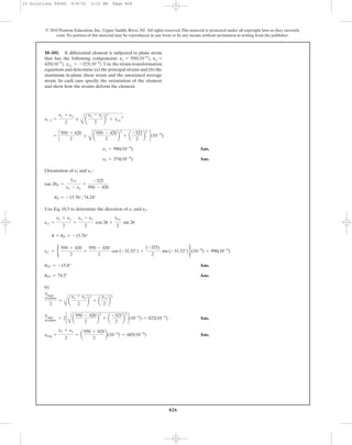
![827
© 2010 Pearson Education, Inc., Upper Saddle River, NJ. All rights reserved.This material is protected under all copyright laws as they currently
exist. No portion of this material may be reproduced, in any form or by any means, without permission in writing from the publisher.
Orientation of :
Ans.
Use Eq. 10.6 to determine the sign of :
gxy = -622(10-6
)
gx¿y¿ = 2c
-(950 - 420)
2
sin (58.4°) +
-325
2
cos (58.4°)d(10-6
)
u = uP = 29.2°
gx¿y¿
2
= -
ex - ey
2
sin 2u +
gxy
2
cos 2u
g max
in-plane
uP = 29.2° and uP = 119°
tan 2uP =
-(ex - ey)
gxy
=
-(950 - 420)
-325
gmax
10–101. Continued
Stress Transformation Equations:
We obtain,
Ans.
Ans.
Ans.= 120A10-6
B
= B
400 + 200
2
-
400 - 200
2
cos (-60°) - a
-300
2
b sin (-60°)R A10-6
B
ey¿ =
ex + ey
2
-
ex - ey
2
cos 2u -
gxy
2
sin 2u
= 23.2A10-6
B
gx¿y¿ = [-(400 - 200) sin (-60°) + (-300) cos (-60°)]A10-6
B
gx¿y¿
2
= - ¢
ex - ey
2
≤ sin 2u +
gxy
2
cos 2u
= 480A10-6
B
= B
400 + 200
2
+
400 - 200
2
cos (-60°) + a
-300
2
b sin (-60°)R A10-6
B
ex¿ =
ex + ey
2
+
ex - ey
2
cos 2u +
gxy
2
sin 2u
ex = 400A10-6
B ey = 200A10-6
B gxy = -300A10-6
B u = -30°
10–102. The state of plane strain on an element is
and
Determine the equivalent state of strain on an element at
the same point oriented 30° clockwise with respect to the
original element. Sketch the results on the element.
gxy = -300110-6
2.Py = 200110-6
2,Px = 400110-6
2,
y
x
dy
dx
Pydy
Pxdx
gxy
2
gxy
2
10 Solutions 46060 6/8/10 3:15 PM Page 827](https://image.slidesharecdn.com/ch08-10combinedloadstransformations-190927203142/85/Ch08-10-combined-loads-transformations-297-320.jpg)


![UNIT-IV-Thin_cylinders and thick _PPT[1].pptx](https://cdn.slidesharecdn.com/ss_thumbnails/unit-iv-thincylindersppt1-250627043420-03d8c9e8-thumbnail.jpg?width=640&height=640&fit=bounds)


