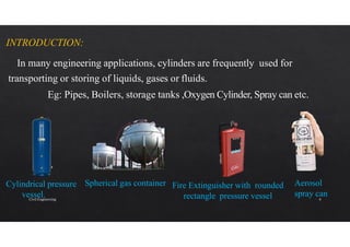
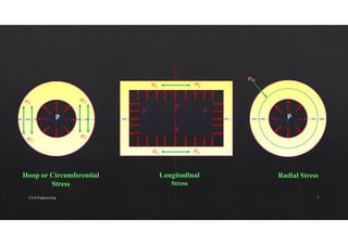
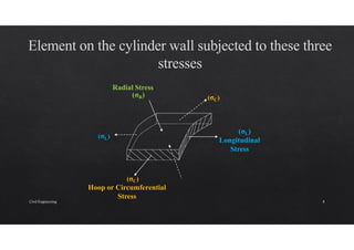
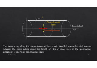
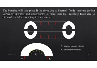
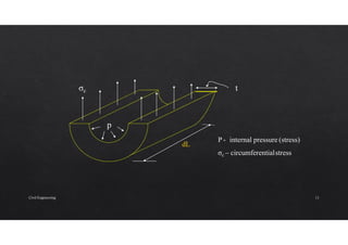
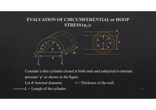
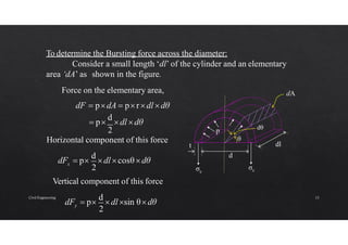
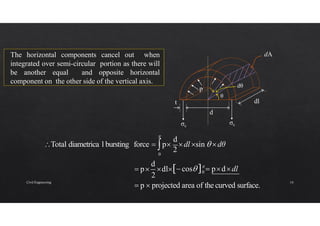
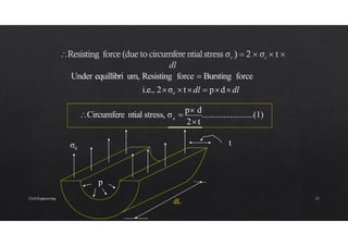
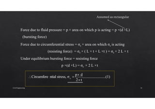
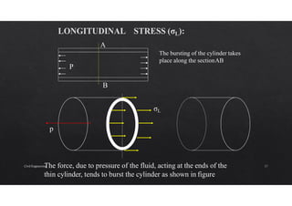
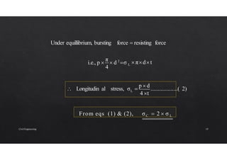
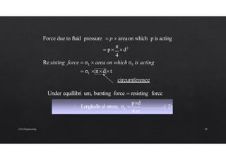
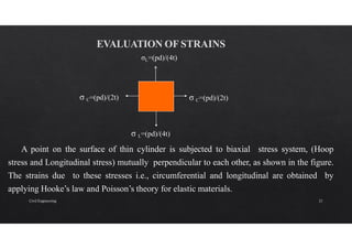
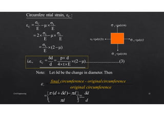
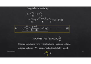
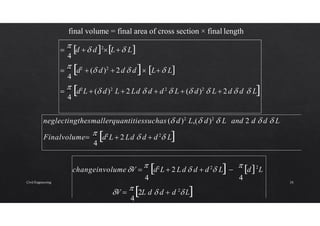
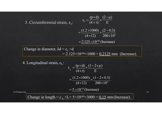
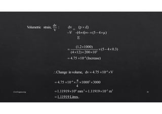
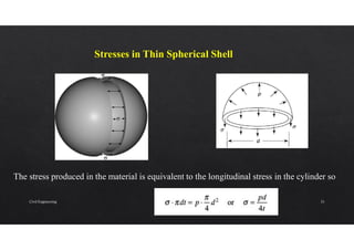
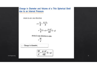
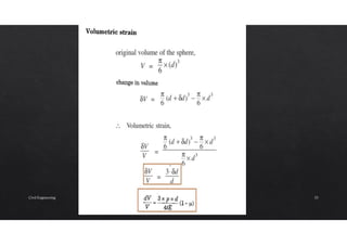
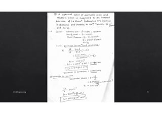
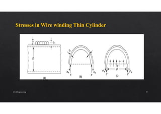
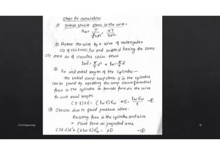
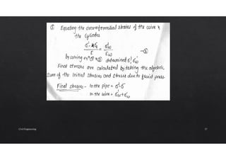
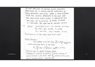
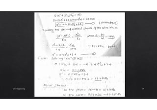
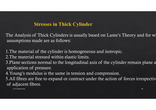
Civil Engineering 1
Objectives of Study
1.Define a Cylindrical shell and distinguish between thin and thick
Cylinders
2.Identify the assumptions involved in the analysis of a thin cylinder,
3.Determine the stresses in a thin cylinder
4.Find the strains and deformation in thin cylinder
5.Find stresses in a wire bound pipe
6.Understand concept of Thick Cylinder
Civil Engineering 2
Civil Engineering 3
INTRODUCTION:
In many engineering applications, cylinders are frequently used for
transporting or storing of liquids, gases or fluids.
Eg: Pipes, Boilers, storage tanks ,Oxygen Cylinder, Spray can etc.
Spherical gas container
Cylindrical pressure
vessel.
Fire Extinguisher with rounded
rectangle pressure vessel
Aerosol
spray can
Civil Engineering 4
The following assumptions are made in order to derive the expressions for
the stresses and strains in thin cylinders :
(i) The diameter of the cylinder is more than 20 times the thickness of the
shell.
(ii) The stresses are uniformly distributed through the thickness of the wall.
(iii) The ends of the cylindrical shell are not supported from sides.
Civil Engineering 5
Civil Engineering 6
p p
p
p
p
p
σC
σC
σC
σC
σL
σL
σL
σL
σR
Hoop or Circumferential
Stress
Longitudinal
Stress
Radial Stress
Civil Engineering 7
Hoop or Circumferential
Stress
(σC)
(σC)
(σL)
Longitudinal
Stress
Radial Stress
(σR)
(σL)
Civil Engineering 8
Longitudinal
axis
Longitudinal stress
t
The stress acting along the circumference of the cylinder is called circumferential stresses
whereas the stress acting along the length of the cylinder (i.e., in the longitudinal
direction ) is known as longitudinal stress
Civil Engineering 9
p
σc σc
P - internal pressure (stress)
σc –circumferentialstress
Civil Engineering 10
P - internal pressure (stress)
σc – circumferentialstress
dL
σc
p
t
Civil Engineering 11
Consider a thin cylinder closed at both ends and subjected to internal
pressure ‘p’ as shown in the figure.
Let d=Internal diameter, t = Thickness of the wall
L = Length of the cylinder.
p d
t
σc
σc
dl
t
p
d
Civil Engineering 12
To determine the Bursting force across the diameter:
Consider a small length ‘dl’ of the cylinder and an elementary
area ‘dA’ as shown in the figure.
x
2
dF  p
d
dlcosθdθ
dA
σc
σc
dl
t
p
d
dθ
θ
Force on the elementary area,
dF  pdA  prdl dθ
 p
d
dl dθ
2
Horizontal component of this force
y
2
dF  p
d
dlsin θdθ
Vertical component of this force
Civil Engineering 13
The horizontal components cancel out when
integrated over semi-circular portion as there will
be another equal and opposite horizontal
component on the other side of the vertical axis.
d
0

Total diametrica l bursting force  p
2
dl sin  dθ
dA
σc
σc
dl
t
p
θ
d
dθ
2
d
0
 p  projected area of the curved surface.
 p dl 
cos  pddl
Civil Engineering 14
c
2t
Circumfere ntial stress, σ 
p d
........................(1)
dL
σc
p
t
Under equillibri um, Resisting force  Bursting force
i.e., 2σc  tdl  pddl
Civil Engineering 15
c
2t
Circumfere ntial stress, σ 
p d
........................(1)
Force due to fluid pressure = p × area on which p is acting = p ×(d ×L)
(bursting force)
Force due to circumferential stress = σc × area on which σc is acting
(resisting force) = σc × ( L × t + L ×t ) = σc × 2 L × t
Under equilibrium bursting force = resisting force
p ×(d ×L) = σc × 2 L ×t
Civil Engineering 16
p
σL
The force, due to pressure of the fluid, acting at the ends of the
thin cylinder, tends to burst the cylinder as shown in figure
A
P
B
The bursting of the cylinder takes
place along the sectionAB
Civil Engineering 17
EVALUATION OF LONGITUDINAL STRESS (σL):
t
σL
p
Longitudin al bursting force (on the end of cylinder)  p 
π
d2
4
Area of crosssection resisting thisforce  π  d  t
Let σL  Longitudin al stress of thematerialof thecylinder.
Resisting force  σL πdt
Civil Engineering 18
L  πdt
i.e., p 
π
 d 2
σ
4
L
4 t
 Longitudin al stress, σ 
p  d
...................( 2)
From eqs (1) & (2), σC  2  σ L
Under equillibrium, bursting force  resisting force
Civil Engineering 19
4
π
L
2
d  σ πdt
i.e., p  ...................( 2)
stress, σL
4t
pd

 Longitudinal
Force due to fluid pressure  p  areaon which p is acting
 p
π
d2
4
Re sisting force  σL  area on which σL is acting
 σL  πd t
circumference
Under equillibri um, bursting force  resisting force
Civil Engineering 20
σ C=(pd)/(2t)
σ C=(pd)/(2t)
σL=(pd)/(4t)
σ L=(pd)/(4t)
A point on the surface of thin cylinder is subjected to biaxial stress system, (Hoop
stress and Longitudinal stress) mutually perpendicular to each other, as shown in the figure.
The strains due to these stresses i.e., circumferential and longitudinal are obtained by
applying Hooke’s law and Poisson’s theory for elastic materials.
Civil Engineering 21
E
εC
Circumfere ntial strain, εC :
μ 
σL

σC
i.e., εC (2 μ)................................(3)

δd

p d
d 4tE
σ C=(pd)/(2
σC=(pd)/(2t)
L
σ =(pd)/(4t)
L
σ =(pd)/(4t)
Note: Let δd be the change in diameter. Then
d
original circumference
c
d

 
  d d d 

d

final circumference - originalcircumference
E
E
(2 μ)
E

σL
E
 2
σL
μ
σL
Civil Engineering 22
E E
εL
Longitudin al strain, εL :
μ 
σC

σL
i.e., εL (12μ)................................(4)

δl

pd
L 4tE
VOLUMETRIC STRAIN,
v
V
Change in volume = δV = final volume – original volume
original volume = V = area of cylindrical shell × length
L

 d 2
4
E E E
(1 2μ)

σL
μ
(2σL )

σL
Civil Engineering 23
final volume = final area of cross section × final length
4
4
4

 d2
L  ( d)2
L  2 Ld  d  d 2
 L  ( d)2
 L  2d  d  L

 d2
 ( d)2
 2d  d L L

 d  d2
L L
4
neglectingthesmallerquantitiessuchas ( d)2
L,( d)2
 L and 2 d  d  L
Finalvolume
 d2
L  2 Ld  d  d 2
 L
4
changeinvolumeV 
 d2
L  2 Ld  d  d 2
 L 
 d2
L
4 4
V 
 2L d  d  d 2
 L
Civil Engineering 24
V π
 d2
L
dv
 4
L
= ε + 2 × εC
V
dV
i.e., (5 4μ).................(5)
V 4tE
dv

p d
(2 μ)
4tE
pd
(1 2μ)  2
4tE
pd

L d
4

 L
 2 
 d
Civil Engineering 25
2
these stresses are normal and act perpendicu lar
to each other.
max
 2t 4t
2

σC -σL
 Maximum Shear stress, τ
pd

pd
i.e., max
τ 
pd
.....................(5)
8t
C
σ =(pd)/(2t)
C
σ =(pd)/(2t)
σ L=(pd)/(4t)
L
σ =(pd)/(4t)
Civil Engineering 26
2
max
 2t 4t
2

σC -σL
 Maximum Shear stress, τ
pd

pd
i.e., max
τ 
pd
.....................(5)
8t
Civil Engineering 27
= 50 N/mm2 = 50 MPa (Tensile).
PROBLEM 1:
A thin cylindrical shell is 3m long and 1m in internal diameter. It is
subjected to internal pressure of 1.2 MPa. If the thickness of the sheet is
12mm, find the circumferential stress, longitudinal stress, changes in
diameter, length and volume . Take E=200 GPa and μ= 0.3.
SOLUTION:
1. Circumferential stress, σC:
σC= (p×d) / (2×t)
= (1.2×1000) / (2× 12)
2. Longitudinal stress, σL:
σL = (p×d) / (4×t)
= σC/2 = 50/2
= 25 N/mm2 = 25 MPa (Tensile).
Civil Engineering 28
Change in length = ε L ×L= 5×10-05×3000 = 0.15 mm(Increase).
(2 μ)
(pd)
Change in diameter, δd = εc ×d
= 2.125×10-04×1000 = 0.2125 mm (Increase).
4. Longitudinal strain, εL:
εc 
(4  t)

E

(1.2 1000)

(2  0.3)
(412) 200103
 2.125 10-04
(Increase)
ε 
(pd)

(1 2μ)
L
(4t) E

(1.21000)

(1 20.3)
(412) 200103
 5 10-05
(Increase)
Civil Engineering 29
(5 4μ)
V
Volumetric strain,
dv
:
(5 40.3)
(412)200103
(1.21000)

 4.75 10-4
(Increase)
Change involume, dv  4.75 10-4
V
 4.75 10-4

π
10002
3000
4
1.11919106
mm3
1.1191910-3
m3
1.11919 Litres.
Civil Engineering 30
Stresses in Thin Spherical Shell
The stress produced in the material is equivalent to the longitudinal stress in the cylinder so
Civil Engineering 31
Civil Engineering 32
Civil Engineering 33
Civil Engineering 34
Stresses in Wire winding Thin Cylinder
Civil Engineering 35
Civil Engineering 36
Civil Engineering 37
Civil Engineering 38
Civil Engineering 39
Stresses in Thick Cylinder
The Analysis of Thick Cylinders is usually based on Lame’s Theory and for wh
assumptions made are as follows:
1.The material of the cylinder is homogeneous and isotropic.
2.The material stressed within elastic limits.
3.Plane sections normal to the longitudinal axis of the cylinder remain plane a
application of pressure.
4.Young’s modulus is the same in tension and compression.
5.All fibres are free to expand or contract under the action of forces irrespective
of adjacent fibres.
Civil Engineering 40
Stresses and strain in Thick Cylinder
Three Stresses and strain are developed
1.Radial (compressive)
2.Circumferential (tensile)
3.Longitudinal (tensile)
Civil Engineering 41

Thin cylinder ppt

  • 1.
  • 2.
    Objectives of Study 1.Definea Cylindrical shell and distinguish between thin and thick Cylinders 2.Identify the assumptions involved in the analysis of a thin cylinder, 3.Determine the stresses in a thin cylinder 4.Find the strains and deformation in thin cylinder 5.Find stresses in a wire bound pipe 6.Understand concept of Thick Cylinder Civil Engineering 2
  • 3.
  • 4.
    INTRODUCTION: In many engineeringapplications, cylinders are frequently used for transporting or storing of liquids, gases or fluids. Eg: Pipes, Boilers, storage tanks ,Oxygen Cylinder, Spray can etc. Spherical gas container Cylindrical pressure vessel. Fire Extinguisher with rounded rectangle pressure vessel Aerosol spray can Civil Engineering 4
  • 5.
    The following assumptionsare made in order to derive the expressions for the stresses and strains in thin cylinders : (i) The diameter of the cylinder is more than 20 times the thickness of the shell. (ii) The stresses are uniformly distributed through the thickness of the wall. (iii) The ends of the cylindrical shell are not supported from sides. Civil Engineering 5
  • 6.
  • 7.
    p p p p p p σC σC σC σC σL σL σL σL σR Hoop orCircumferential Stress Longitudinal Stress Radial Stress Civil Engineering 7
  • 8.
  • 9.
    Longitudinal axis Longitudinal stress t The stressacting along the circumference of the cylinder is called circumferential stresses whereas the stress acting along the length of the cylinder (i.e., in the longitudinal direction ) is known as longitudinal stress Civil Engineering 9
  • 10.
    p σc σc P -internal pressure (stress) σc –circumferentialstress Civil Engineering 10
  • 11.
    P - internalpressure (stress) σc – circumferentialstress dL σc p t Civil Engineering 11
  • 12.
    Consider a thincylinder closed at both ends and subjected to internal pressure ‘p’ as shown in the figure. Let d=Internal diameter, t = Thickness of the wall L = Length of the cylinder. p d t σc σc dl t p d Civil Engineering 12
  • 13.
    To determine theBursting force across the diameter: Consider a small length ‘dl’ of the cylinder and an elementary area ‘dA’ as shown in the figure. x 2 dF  p d dlcosθdθ dA σc σc dl t p d dθ θ Force on the elementary area, dF  pdA  prdl dθ  p d dl dθ 2 Horizontal component of this force y 2 dF  p d dlsin θdθ Vertical component of this force Civil Engineering 13
  • 14.
    The horizontal componentscancel out when integrated over semi-circular portion as there will be another equal and opposite horizontal component on the other side of the vertical axis. d 0  Total diametrica l bursting force  p 2 dl sin  dθ dA σc σc dl t p θ d dθ 2 d 0  p  projected area of the curved surface.  p dl  cos  pddl Civil Engineering 14
  • 15.
    c 2t Circumfere ntial stress,σ  p d ........................(1) dL σc p t Under equillibri um, Resisting force  Bursting force i.e., 2σc  tdl  pddl Civil Engineering 15
  • 16.
    c 2t Circumfere ntial stress,σ  p d ........................(1) Force due to fluid pressure = p × area on which p is acting = p ×(d ×L) (bursting force) Force due to circumferential stress = σc × area on which σc is acting (resisting force) = σc × ( L × t + L ×t ) = σc × 2 L × t Under equilibrium bursting force = resisting force p ×(d ×L) = σc × 2 L ×t Civil Engineering 16
  • 17.
    p σL The force, dueto pressure of the fluid, acting at the ends of the thin cylinder, tends to burst the cylinder as shown in figure A P B The bursting of the cylinder takes place along the sectionAB Civil Engineering 17
  • 18.
    EVALUATION OF LONGITUDINALSTRESS (σL): t σL p Longitudin al bursting force (on the end of cylinder)  p  π d2 4 Area of crosssection resisting thisforce  π  d  t Let σL  Longitudin al stress of thematerialof thecylinder. Resisting force  σL πdt Civil Engineering 18
  • 19.
    L  πdt i.e.,p  π  d 2 σ 4 L 4 t  Longitudin al stress, σ  p  d ...................( 2) From eqs (1) & (2), σC  2  σ L Under equillibrium, bursting force  resisting force Civil Engineering 19
  • 20.
    4 π L 2 d  σπdt i.e., p  ...................( 2) stress, σL 4t pd   Longitudinal Force due to fluid pressure  p  areaon which p is acting  p π d2 4 Re sisting force  σL  area on which σL is acting  σL  πd t circumference Under equillibri um, bursting force  resisting force Civil Engineering 20
  • 21.
    σ C=(pd)/(2t) σ C=(pd)/(2t) σL=(pd)/(4t) σL=(pd)/(4t) A point on the surface of thin cylinder is subjected to biaxial stress system, (Hoop stress and Longitudinal stress) mutually perpendicular to each other, as shown in the figure. The strains due to these stresses i.e., circumferential and longitudinal are obtained by applying Hooke’s law and Poisson’s theory for elastic materials. Civil Engineering 21
  • 22.
    E εC Circumfere ntial strain,εC : μ  σL  σC i.e., εC (2 μ)................................(3)  δd  p d d 4tE σ C=(pd)/(2 σC=(pd)/(2t) L σ =(pd)/(4t) L σ =(pd)/(4t) Note: Let δd be the change in diameter. Then d original circumference c d      d d d   d  final circumference - originalcircumference E E (2 μ) E  σL E  2 σL μ σL Civil Engineering 22
  • 23.
    E E εL Longitudin alstrain, εL : μ  σC  σL i.e., εL (12μ)................................(4)  δl  pd L 4tE VOLUMETRIC STRAIN, v V Change in volume = δV = final volume – original volume original volume = V = area of cylindrical shell × length L   d 2 4 E E E (1 2μ)  σL μ (2σL )  σL Civil Engineering 23
  • 24.
    final volume =final area of cross section × final length 4 4 4   d2 L  ( d)2 L  2 Ld  d  d 2  L  ( d)2  L  2d  d  L   d2  ( d)2  2d  d L L   d  d2 L L 4 neglectingthesmallerquantitiessuchas ( d)2 L,( d)2  L and 2 d  d  L Finalvolume  d2 L  2 Ld  d  d 2  L 4 changeinvolumeV   d2 L  2 Ld  d  d 2  L   d2 L 4 4 V   2L d  d  d 2  L Civil Engineering 24
  • 25.
    V π  d2 L dv 4 L = ε + 2 × εC V dV i.e., (5 4μ).................(5) V 4tE dv  p d (2 μ) 4tE pd (1 2μ)  2 4tE pd  L d 4   L  2   d Civil Engineering 25
  • 26.
    2 these stresses arenormal and act perpendicu lar to each other. max  2t 4t 2  σC -σL  Maximum Shear stress, τ pd  pd i.e., max τ  pd .....................(5) 8t C σ =(pd)/(2t) C σ =(pd)/(2t) σ L=(pd)/(4t) L σ =(pd)/(4t) Civil Engineering 26
  • 27.
    2 max  2t 4t 2  σC-σL  Maximum Shear stress, τ pd  pd i.e., max τ  pd .....................(5) 8t Civil Engineering 27
  • 28.
    = 50 N/mm2= 50 MPa (Tensile). PROBLEM 1: A thin cylindrical shell is 3m long and 1m in internal diameter. It is subjected to internal pressure of 1.2 MPa. If the thickness of the sheet is 12mm, find the circumferential stress, longitudinal stress, changes in diameter, length and volume . Take E=200 GPa and μ= 0.3. SOLUTION: 1. Circumferential stress, σC: σC= (p×d) / (2×t) = (1.2×1000) / (2× 12) 2. Longitudinal stress, σL: σL = (p×d) / (4×t) = σC/2 = 50/2 = 25 N/mm2 = 25 MPa (Tensile). Civil Engineering 28
  • 29.
    Change in length= ε L ×L= 5×10-05×3000 = 0.15 mm(Increase). (2 μ) (pd) Change in diameter, δd = εc ×d = 2.125×10-04×1000 = 0.2125 mm (Increase). 4. Longitudinal strain, εL: εc  (4  t)  E  (1.2 1000)  (2  0.3) (412) 200103  2.125 10-04 (Increase) ε  (pd)  (1 2μ) L (4t) E  (1.21000)  (1 20.3) (412) 200103  5 10-05 (Increase) Civil Engineering 29
  • 30.
    (5 4μ) V Volumetric strain, dv : (540.3) (412)200103 (1.21000)   4.75 10-4 (Increase) Change involume, dv  4.75 10-4 V  4.75 10-4  π 10002 3000 4 1.11919106 mm3 1.1191910-3 m3 1.11919 Litres. Civil Engineering 30
  • 31.
    Stresses in ThinSpherical Shell The stress produced in the material is equivalent to the longitudinal stress in the cylinder so Civil Engineering 31
  • 32.
  • 33.
  • 34.
  • 35.
    Stresses in Wirewinding Thin Cylinder Civil Engineering 35
  • 36.
  • 37.
  • 38.
  • 39.
  • 40.
    Stresses in ThickCylinder The Analysis of Thick Cylinders is usually based on Lame’s Theory and for wh assumptions made are as follows: 1.The material of the cylinder is homogeneous and isotropic. 2.The material stressed within elastic limits. 3.Plane sections normal to the longitudinal axis of the cylinder remain plane a application of pressure. 4.Young’s modulus is the same in tension and compression. 5.All fibres are free to expand or contract under the action of forces irrespective of adjacent fibres. Civil Engineering 40
  • 41.
    Stresses and strainin Thick Cylinder Three Stresses and strain are developed 1.Radial (compressive) 2.Circumferential (tensile) 3.Longitudinal (tensile) Civil Engineering 41