Downloaded 104 times
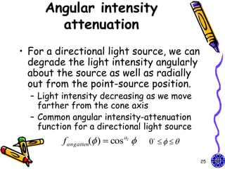
![Homogeneous
coordinates
• Original homogeneous coordinates:
x x p 1 0 0 0 x
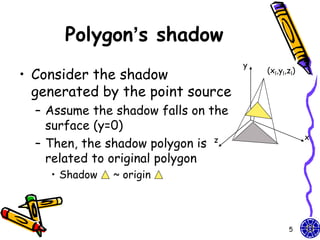
xp
y / d y 0 1 0 0 y
p
yp = y zp 0 0 1 0 z
zp
z 0 1
0 0 1
y / d 1 d
Perspective projection matrix: Our light can be
shadow projection Matrix moved by design
GLfloat light[3]={0.0, 10.0, 0.0};
GLfloat m[16]; light[0]=10.0*sin((6.28/180.0)*theta);
light[2]=10.0*cos((6.28/180.0)*theta);
for(i=0;i<16;i++) m[i]=0.0;
m[0]=m[5]=m[10]=1.0; m[7]=-1.0/light[1];
8](https://image.slidesharecdn.com/cg-shadowslighttexture-course10-111015014206-phpapp01/85/CG-OpenGL-Shadows-Light-Texture-course-10-8-320.jpg)
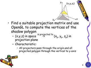
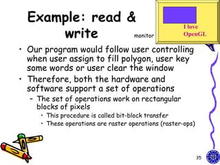
![Polygon & its shadow
/* define unit square polygon */
glColor3f(1.0, 0.0, 0.0);/* set drawing/fill color to red*/
glBegin(GL_POLYGON);
glVertex3f(…); …
glEnd();
glPushMatrix(); //save state
glTranslatef(light[0], light[1],light[2]); //translate back
glMultMatrixf(m); //project
glTranslatef(-light[0], -light[1],-light[2]); //return origin
//shadow object
glColor3f(0.0,0.0,0.0);
glBegin(GL_POLYGON);
glVertex3f(…);…
glEnd();
glPopMatrix(); //restore state
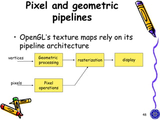
How to design the different size
between original polygon & its shadow?
10](https://image.slidesharecdn.com/cg-shadowslighttexture-course10-111015014206-phpapp01/85/CG-OpenGL-Shadows-Light-Texture-course-10-10-320.jpg)
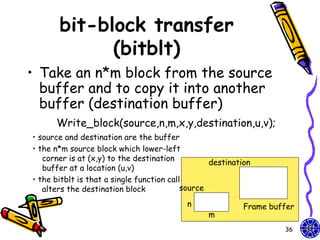
![Viewer (camera) moving (1)
• Viewer move the camera in a scene by
depressing the x, X, y, Y, z, Z keys on
keyboard
void keys(unsigned char key, int x, int y){
if(key == ‘x’) viewer[0] -= 1.0;
if(key == ‘X’) viewer[0] += 1.0;
if(key == ‘y’) viewer[1] -= 1.0;
if(key == ‘Y’) viewer[1] += 1.0;
if(key == ‘z’) viewer[2] -= 1.0;
if(key == ‘Z’) viewer[2] += 1.0;
glutPostRedisplay(); }
Walking in a scene.
What problem happen if object is walked far away?
13](https://image.slidesharecdn.com/cg-shadowslighttexture-course10-111015014206-phpapp01/85/CG-OpenGL-Shadows-Light-Texture-course-10-13-320.jpg)
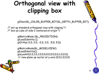
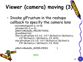
![Viewer (camera) moving (2)
• The gluLookAt function provides a
simple way to reposition and reorient
the camera
void display(void){
glClear(GL_COLOR_BUFFER_BIT | GL_DEPTH_BUFFER_BIT);
glLoadIdentity();
gluLookAt(viewer[0],viewer[1],viewer[2],0.0,0.0,0.0,0.0,1.0,0.0);
/* rotate cube */
glRotatef(theta[0], 1.0, 0.0, 0.0);
glRotatef(theta[1], 0.0, 1.0, 0.0);
glRotatef(theta[2], 0.0, 0.0, 1.0);
colorcube();
glFlush();
glutSwapBuffers(); }
14](https://image.slidesharecdn.com/cg-shadowslighttexture-course10-111015014206-phpapp01/85/CG-OpenGL-Shadows-Light-Texture-course-10-14-320.jpg)
![Homework
• Walking in a scene
void polygon(int a, int b, int c , int d){
– Hint: Object glBegin(GL_POLYGON);
walking or walking glColor3fv(colors[a]);
glNormal3fv(normals[a]);
above floor glVertex3fv(vertices[a]);
glColor3fv(colors[b]);
– Example: color glNormal3fv(normals[b]);
cube glVertex3fv(vertices[b]);
glColor3fv(colors[c]);
glNormal3fv(normals[c]);
glVertex3fv(vertices[c]);
glColor3fv(colors[d]);
glNormal3fv(normals[d]);
glVertex3fv(vertices[d]);
glEnd(); }
demo
31](https://image.slidesharecdn.com/cg-shadowslighttexture-course10-111015014206-phpapp01/85/CG-OpenGL-Shadows-Light-Texture-course-10-31-320.jpg)

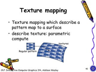
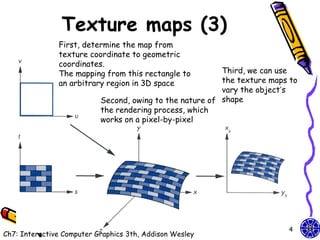
![Texture maps (1)
• Texture map on a geometric object where
mapped to screen coordinates for display
– Object in spatial coordinates [(x,y,z) or
(x,y,z,w)] & texture elements (s,t)
• The mapping function:
x = x(s,t), y = y(s,t), z = z(s,t), w = w(s,t)
• The inverse function:
s = s(x,y,z,w), t = t(x,y,z,w)
42](https://image.slidesharecdn.com/cg-shadowslighttexture-course10-111015014206-phpapp01/85/CG-OpenGL-Shadows-Light-Texture-course-10-42-320.jpg)
![2D texture mapping (1)
• Support we have a 512*512 image my_texels
GLubye my_texels[512][512]
• Specify this array is too be used as a 2D texture
glTexImage2D(GL_TEXTURE_2D, level, components,
width, height, border, format,type,tarry);
– tarray size is the same the width*height
– The value components is the (1-4) of color components
(RGBA) or 3 (RGB)
– The format (RGBA) = 4 or 3 (RGB)
– In processor memory, tarry’s pixels are moved through
the pixel pipeline (** not in the frame buffer)
– The parameters level and border give us fine control
Ex: glTexImage2D(GL_TEXTURE_2D, 0, 3, 512, 512,
0, GL_RGB,GL_UNSIGNED_BYTE,my_texels);
51](https://image.slidesharecdn.com/cg-shadowslighttexture-course10-111015014206-phpapp01/85/CG-OpenGL-Shadows-Light-Texture-course-10-51-320.jpg)

The document discusses various techniques for constructing shadows and lighting effects in 3D computer graphics, including using projection matrices to generate shadow polygons and accounting for factors like light source positioning, radial intensity attenuation, and surface reflectance properties. It also examines methods for animating camera movement and introducing texture mapping to surfaces.


![74676371-Coagulation-and-Flocculation[1].ppt](https://cdn.slidesharecdn.com/ss_thumbnails/74676371-coagulation-and-flocculation1-260116154109-a3cbf55e-thumbnail.jpg?width=640&height=640&fit=bounds)


