The document provides details on the design process for a centrifugal pump given specific head, flow rate, and speed requirements provided by the client. Key steps include:
1) Calculating hydraulic parameters like flow rate, horsepower required, and shaft torque to size the shaft diameter.
2) Designing dimensions of the impeller like eye diameter, inlet and outlet angles, and widths to achieve the required flow while minimizing leakage losses.
3) Iteratively adjusting dimensions like impeller diameter until the calculated head matches the specified head within an acceptable tolerance.
Basics Fundamentals and working Principle of Centrifugal Pump.SHASHI BHUSHAN
Basics Fundamentals and working Principle of Centrifugal Pump. Centrifugal pumps are the rotodynamic machines that convert mechanical energy of shaft into kinetic and pressure energy of Fluid which may be used to raise the level of fluid. A centrifugal pump is named so, because the energy added by the impeller to the fluid is largely due to centrifugal effects.
Predicting Performance Curves of Centrifugal Pumps in the Absence of OEM DataVijay Sarathy
Chemical and Mechanical Engineers in the oil & gas industry often carry out the task of conducting technical studies to evaluate piping and pipeline systems during events such as pump trips and block valve failures that can lead to pipes cracking at the welded joints, pump impellers rotating in the reverse direction and damaged pipe supports due to excessive vibrations to name a few. Although much literature is available to mitigate such disturbances, a key set of data to conduct transient studies are pump performance curves, a plot between pump head and flow.
The present paper is aimed at applying engineering research in industrial applications for practicing engineers. It provides a methodology called from available literature from past researchers, allowing engineers to predict performance curves for a Volute Casing End Suction Single Stage Radial Pump. In the current undertaking, the pump in question is not specific to any one industry but the principles are the same for a Volute Casing End suction radial pump.
Pumps are used to add energy to fluids (gases, liquids, or slurries) in order to produce flow or increase pressure. They can perform many different functions, including moving a fluid from one location to another, recirculating a fluid in a closed system, such as in a heating or cooling system, and providing pressure, such as in hydraulic systems. These functions are performed primarily by two different types of pumps: centrifugal and positive displacement.
Pumps, Types of Pumps, Classification of Pumps and Characteristics of Pumps.Talal Khan
This Presentation Discus Pumps(Centrifugal and Positive Displacement) Also it Discusses other properties of pumps.
It also consists of Images and animations of the Pumps.
A steam turbine is a prime mover in which the potential energy of the steam is transformed into kinetic energy and later in its turn is transformed into the mechanical energy of rotation of the turbine shaft
" Pedal Powered Water Purification By Reverse Osmosis"
The Earth is covered in over 75% water, yet one of the world’s greatest issues is a lack drinking water. “Nearly one billion people do not have access to clean drinking water”. That is about one eighth of all the people living on earth right now. Every year, almost four million people die from water-related diseases and 98% of those occur in the developing world. Humans can live for weeks without food, but only a few days without water. Many people in developing countries barely have access to any water source at all and for those that do, the water is completely filthy and disease-ridden.
Clearly, access to potable water around the world is an exceedingly urgent issue in which action should be taken immediately. In response to such a need, this idea is proposed to produce clean drinking water by reverse osmosis filtration by means of human power. There are several means to purify water; however, because of its incredible thoroughness, a reverse osmosis system has been preferentially selected for this design
This article helps you understand the term NPSH, how it is calculated and its importance when selecting a centrifugal pump. This basic knowledge of NPSH will help you go a long way in identifying potential problems in your pump even before they occur.
Gas Turbine Theory - Principle of Operation and ConstructionSahyog Shishodia
This presentation tells all about basic principle behind Gas Turbine, their working, operation and construction. How they came into existence and where are they used.
Design Considerations for Antisurge Valve SizingVijay Sarathy
Centrifugal Compressors experience a phenomenon called “Surge” which can be defined as a situation where a flow reversal from the discharge side back into the compressor casing causing mechanical damage.
The reasons are multitude ranging from driver failure, power failure, upset process conditions, start up, shutdown, failure of anti-surge mechanisms, check valve failure to operator error to name a few. The consequences of surge are more mechanical in nature whereby ball bearings, seals, thrust bearing, collar shafts, impellers wear out and sometimes depending on the how powerful are the surge forces, cause fractures to the machinery parts due to excessive vibrations.
The following tutorial explains how to size an anti-surge valve for a single stage VSD system for Concept/Basic Engineering purposes.
Rudder Control Analysis / Hydraulic Pump AnalysisAndrè G. Odu
The objective of the lab is to analyze the performance of a hydraulic pump, responsible for the transfer of fluid between two tanks at a constant flow, in function of its rotational speed.
As the RPM vary from 0 to 4000 we are mainly interested in studying the speed, flow rate and pressures when entering and exiting the pump, the coefficient of head losses associated with the delivery duct, the required hydraulic power and the hydraulic power generated.
As the lab progresses, we find ourselves needing to solve the problem of cavitation that manifests itself in the aspiration duct, and are asked to calculate the plate angle of orientation when the cylinders are placed along a circumference with diameter of 60mm.
The objective of the lab is to analyze the operativity of an actuator used to control the movements of an Airbus A320 rudder.
The Airbus A320 uses three actuators with double redundancy, each of which is designed to control the mobile surface independently.
Given the opposing moment that must be overcome we can calculate the muscular force required to control the mobile surface, from which we can determine the dimensional specifics for the actuator that will be introduced, the equations of operation and the approximate time required to complete the movement.
The turbo machine is an energy conversion device which converts mechanical energy to kinetic/pressure energy or vice versa. The conversion is done through the dynamic interaction between a continuously flowing fluid and rotating machine component. Turbo machines comprise various types of fans, blowers, compressors, pumps, turbines etc. More and more experimental research work is available in the field of turbo machine design and its evaluation. Literature review has revealed that a few literatures are available on three dimensional numerical analysis of a centrifugal fan/blower. Literature review in present work is highly focused on centrifugal blower and use of CFD techniques in turbo machines. In this course of work, input parameters and design parameters of centrifugal blower is obtained as per church and Osborne design methodology developed by Kinnari Shah, PROF. NitinVibhakar. Fluid model is made as per this design data in PRO-E SOFTWARE. And this fluid model is simulated using computational fluid dynamics (CFD) approach in ANSYS (CFX). Numerical analysis carried out in this work is to understand the flow characteristics at design and off-design conditions under varying mass flow rates, varying rotational speeds and number of blades in both design methodology. This numerical analysis is under consideration of steady flow and for rotational domain (frozen rotor interference) is used. Performance curves are obtained under different variable inlet parameters like volume flow rate, rotational speed and number of impeller blades. Here mass flow rate as a inlet boundary condition and static pressure as a outlet boundary condition. Volume flow rate is changed by changing the mass flow rate at inlet. Overall work carried out on flow behaviour and performance graphs for different cases are discussed in length in results and discussions chapter. Comparative evaluation of two design method indicates that error in static pressure gradient is higher in Osborne design rather than church design, and performance parameters are better for church design than the Osborne design.
Predicting Performance Curves of Centrifugal Pumps in the Absence of OEM DataVijay Sarathy
Chemical and Mechanical Engineers in the oil & gas industry often carry out the task of conducting technical studies to evaluate piping and pipeline systems during events such as pump trips and block valve failures that can lead to pipes cracking at the welded joints, pump impellers rotating in the reverse direction and damaged pipe supports due to excessive vibrations to name a few. Although much literature is available to mitigate such disturbances, a key set of data to conduct transient studies are pump performance curves, a plot between pump head and flow.
The present paper is aimed at applying engineering research in industrial applications for practicing engineers. It provides a methodology called from available literature from past researchers, allowing engineers to predict performance curves for a Volute Casing End Suction Single Stage Radial Pump. In the current undertaking, the pump in question is not specific to any one industry but the principles are the same for a Volute Casing End suction radial pump.
,friction pipe ,friction loss along a pipe ,pipe ,along a ,loss along ,loss along a ,friction loss ,friction loss along a ,loss along a pipe ,along a pipe ,friction loss alon ,friction loss along a p ,loss along a pip
Wall static pressure distribution due to confined impinging circular air jeteSAT Publishing House
IJRET : International Journal of Research in Engineering and Technology is an international peer reviewed, online journal published by eSAT Publishing House for the enhancement of research in various disciplines of Engineering and Technology. The aim and scope of the journal is to provide an academic medium and an important reference for the advancement and dissemination of research results that support high-level learning, teaching and research in the fields of Engineering and Technology. We bring together Scientists, Academician, Field Engineers, Scholars and Students of related fields of Engineering and Technology.
Guide to the selection of UNIQA electric pumps - Zenit GroupZenit Group
The introduction of UNIQA® pumps requires sales technicians and resellers to be able to select and ex-plain their constructional and functional characteristics. They must therefore be familiar with the basic technical concepts applicable to all pumps, as well as those which apply specifically to the UNIQA® range:
- Basic concepts of hydraulics
- Q-H curve (duty point)
- Pump - Motor (P1 - P2 - P3)
- Efficiency
- Concept of hydraulics
- Applying motors of various power ratings to a given impeller
- Operation with frequency variator
- Other selection criteria (materials, versions, etc.)
Macroeconomics- Movie Location
This will be used as part of your Personal Professional Portfolio once graded.
Objective:
Prepare a presentation or a paper using research, basic comparative analysis, data organization and application of economic information. You will make an informed assessment of an economic climate outside of the United States to accomplish an entertainment industry objective.
The French Revolution, which began in 1789, was a period of radical social and political upheaval in France. It marked the decline of absolute monarchies, the rise of secular and democratic republics, and the eventual rise of Napoleon Bonaparte. This revolutionary period is crucial in understanding the transition from feudalism to modernity in Europe.
For more information, visit-www.vavaclasses.com
Normal Labour/ Stages of Labour/ Mechanism of LabourWasim Ak
Normal labor is also termed spontaneous labor, defined as the natural physiological process through which the fetus, placenta, and membranes are expelled from the uterus through the birth canal at term (37 to 42 weeks
June 3, 2024 Anti-Semitism Letter Sent to MIT President Kornbluth and MIT Cor...Levi Shapiro
Letter from the Congress of the United States regarding Anti-Semitism sent June 3rd to MIT President Sally Kornbluth, MIT Corp Chair, Mark Gorenberg
Dear Dr. Kornbluth and Mr. Gorenberg,
The US House of Representatives is deeply concerned by ongoing and pervasive acts of antisemitic
harassment and intimidation at the Massachusetts Institute of Technology (MIT). Failing to act decisively to ensure a safe learning environment for all students would be a grave dereliction of your responsibilities as President of MIT and Chair of the MIT Corporation.
This Congress will not stand idly by and allow an environment hostile to Jewish students to persist. The House believes that your institution is in violation of Title VI of the Civil Rights Act, and the inability or
unwillingness to rectify this violation through action requires accountability.
Postsecondary education is a unique opportunity for students to learn and have their ideas and beliefs challenged. However, universities receiving hundreds of millions of federal funds annually have denied
students that opportunity and have been hijacked to become venues for the promotion of terrorism, antisemitic harassment and intimidation, unlawful encampments, and in some cases, assaults and riots.
The House of Representatives will not countenance the use of federal funds to indoctrinate students into hateful, antisemitic, anti-American supporters of terrorism. Investigations into campus antisemitism by the Committee on Education and the Workforce and the Committee on Ways and Means have been expanded into a Congress-wide probe across all relevant jurisdictions to address this national crisis. The undersigned Committees will conduct oversight into the use of federal funds at MIT and its learning environment under authorities granted to each Committee.
• The Committee on Education and the Workforce has been investigating your institution since December 7, 2023. The Committee has broad jurisdiction over postsecondary education, including its compliance with Title VI of the Civil Rights Act, campus safety concerns over disruptions to the learning environment, and the awarding of federal student aid under the Higher Education Act.
• The Committee on Oversight and Accountability is investigating the sources of funding and other support flowing to groups espousing pro-Hamas propaganda and engaged in antisemitic harassment and intimidation of students. The Committee on Oversight and Accountability is the principal oversight committee of the US House of Representatives and has broad authority to investigate “any matter” at “any time” under House Rule X.
• The Committee on Ways and Means has been investigating several universities since November 15, 2023, when the Committee held a hearing entitled From Ivory Towers to Dark Corners: Investigating the Nexus Between Antisemitism, Tax-Exempt Universities, and Terror Financing. The Committee followed the hearing with letters to those institutions on January 10, 202
How to Make a Field invisible in Odoo 17Celine George
It is possible to hide or invisible some fields in odoo. Commonly using “invisible” attribute in the field definition to invisible the fields. This slide will show how to make a field invisible in odoo 17.
Embracing GenAI - A Strategic ImperativePeter Windle
Artificial Intelligence (AI) technologies such as Generative AI, Image Generators and Large Language Models have had a dramatic impact on teaching, learning and assessment over the past 18 months. The most immediate threat AI posed was to Academic Integrity with Higher Education Institutes (HEIs) focusing their efforts on combating the use of GenAI in assessment. Guidelines were developed for staff and students, policies put in place too. Innovative educators have forged paths in the use of Generative AI for teaching, learning and assessments leading to pockets of transformation springing up across HEIs, often with little or no top-down guidance, support or direction.
This Gasta posits a strategic approach to integrating AI into HEIs to prepare staff, students and the curriculum for an evolving world and workplace. We will highlight the advantages of working with these technologies beyond the realm of teaching, learning and assessment by considering prompt engineering skills, industry impact, curriculum changes, and the need for staff upskilling. In contrast, not engaging strategically with Generative AI poses risks, including falling behind peers, missed opportunities and failing to ensure our graduates remain employable. The rapid evolution of AI technologies necessitates a proactive and strategic approach if we are to remain relevant.
Read| The latest issue of The Challenger is here! We are thrilled to announce that our school paper has qualified for the NATIONAL SCHOOLS PRESS CONFERENCE (NSPC) 2024. Thank you for your unwavering support and trust. Dive into the stories that made us stand out!
Digital Tools and AI for Teaching Learning and Research
Centrifugal pump design rev 2
1. CENTRIFUGAL PUMP DESIGN1
The client will usually specify the desired head and pump capacity. The type and speed of the
driver may also be specified. Speed is governed by considerations of cost and efficiency as well as drivers
available to the client. Given these parameters, the task of the engineer is to minimize cost.
Which cost to minimize, first cost or life-cycle cost, however, is an important consideration.
From a life cycle viewpoint, we must take into account power consumption and operation and
maintenance costs. These considerations call for optimizing efficiency, reliability (the mean time between
failure) and maintainability (the mean time to repair). In general, designing to optimize these categories
results in increased costs. Often, these considerations are not very important and we can design for
minimum first cost. In appropriate cases, the engineer should initiate a dialog with the client concerning
available options. For example, designing a boiler feed pump that operates continuously would probably
call for maximizing efficiency. Efficiency considerations would not be so important, however, for a
drainage pump that is only required to operate occasionally.
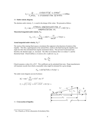
PIPE CONNECTIONS AND VELOCITIES
The diameter of the suction pipe is usually made larger that the pump suction flange and both are
made larger than the discharge flange and pipe. Church recommends keeping the velocity at the suction
flange about 9 or 10 ft/s and that at the discharge flange between 18 and 25 ft/s.
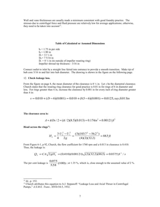
LEAKAGE LOSSES
To design the impeller, account must be taken of leakage from the discharge side back to the
suction side. To reduce the leakage, wearing rings are fitted to the impeller and casing. These rings are
designed with specified clearances. The leakage across each ring can be calculated from the following
formula:
2L LQ CA gH=
where: C = flow coefficient2
A = leakage area = / 2Dsπ
D = mean clearance diameter
s = diametrical clearance 3
0.010 ( 6)(0.001)D in= + −
For small wearing rings with precise machining and ball bearings, the minimum clearance may
be reduced to 0.008 in.
( )[ ]H U U gL = −
3
4
22
2
1
2
/ 3
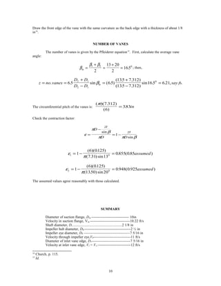
IMPELLER INLET DIMENSIONS AND VANE ANGLE
The diameter of the impeller eye, Do, is dependent on the shaft
diameter, Ds, which must initially be approximated. The hub diameter,
1
This section is based on Church, A.H., Centrifugal Pumps and Blowers,
Ch. 6, John Wiley & Sons, 1950.
2
Id. Fig. 6-1, p. 92.
3
Attributed by Church to Stepanoff, A.J., Trans. A.S.M.E., HYD-54-5, 1932.
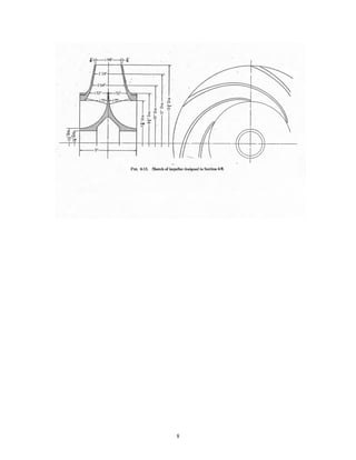
1
2. DH , is made 5/16 to ½ inch larger than Ds. After estimating Ds and DH ,
Do is based on the known flowrate. The inlet vane edge diameter, D1, is
made about the same as Do to ensure smooth flow.
EXAMPLE OF IMPELLER DESIGN4
Specified conditions: Required head: hP = 150ft
Required flowrate: Q = 2500 gpm
Required speed N = 1760 rpm
1. Quantity flowrate:
( )
( ) ( )
3
32500 min
5.57 /
min 60 7.48
gal ft
Q ft s
s gal
= =
2. Mass flowrate:
( ) ( )3
3
5.57 62.4
348 /m
ft lbm
m lb s
s ft
= =&
3. Specific speed: Assume a double suction impeller; then, Q = 2500/2 = 1250gpm, and:
[ ]
N
rpm Q gpm
h ft
rpmsd
p
= = =
ω( ) ( )
( )
( )
( )/ /3 4 3 4
1760 1250
150
1450
For this specific speed, a radial flow pump is indicated.5
4. Water horsepower.
2
2
(32.2) (150)(348)
550 (550) 32.2
ft ftmgh lbm s hp s
WHP
s s ft lbf ft
⋅
= =
⋅
&
94.6WHP hp=
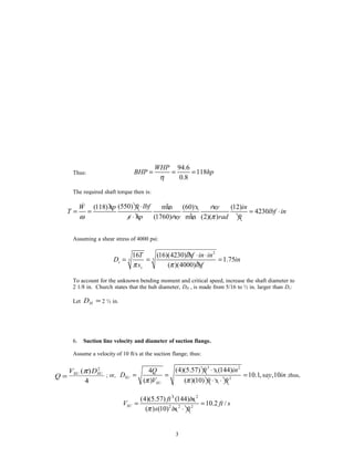
5. Shaft diameter. Calculate shaft diameter based on torque. Increase the calculated value
somewhat to allow for bending moment which is unknown at this point and to ensure that
the critical speed exceeds the operational speed by a reasonable margin. The bending
moment will depend on the weight distribution of the shaft and any unbalanced radial thrust
acting on the impeller. From the figure shown below, with the given flow of 2500 gpm and
calculated value of specific speed of 1450, we select a tentative value of efficiency of 80%.
4
See, Church, p. 107-117.
5
See,Munson, Fig. 12.18, p. 812.
2
3. Thus:
94.6
118
0.8
WHP
BHP hp
η
= = =
The required shaft torque then is:
(550)(118) min (60) (12)
4230
(1760) min (2)( )
ft lbfW hp s rev in
T lbf in
s hp rev rad ftω π
⋅
= = = ⋅
⋅
&
Assuming a shear stress of 4000 psi:
2
33
16 (16)(4230)
1.75
( )(4000)
s
s
T lbf in in
D in
s lbfπ π
⋅ ⋅
= = =
To account for the unknown bending moment and critical speed, increase the shaft diameter to
2 1/8 in. Church states that the hub diameter, DH , is made from 5/16 to ½ in. larger than Ds:
Let DH = 2 ½ in.
6. Suction line velocity and diameter of suction flange.
Assume a velocity of 10 ft/s at the suction flange; thus:
Q
V DSU SU
=
( )π 2
4
; or,
3 2
2
(4)(5.57) (144)4
10.1, ,10
( ) ( )(10)
SU
SU
ft s inQ
D say in
V ft s ftπ π
⋅
= = =
⋅ ⋅
;thus,
3 2
2 2 2
(4)(5.57) (144)
10.2 /
( ) (10)
SU
ft in
V ft s
s in ftπ
= =
⋅
3
4. Assume the velocity at the eye of the impeller is 11 ft/s.
For a double suction pump, assume that the leakage will not exceed 2%. Dividing the total flow by 2
gives:
Q V A V
D DH
= = −0 0 0
0
2 2
4 4
( )
π π
2 2
0
0
(4)(1.02) (4)(1.02)(5.57)(144) 5
(2.5) 7.33 , ,7
( )(2) ( )(2)(11) 16
H
Q
D D in say in
Vπ π
= + = + =
7. Wheel inlet dimensions and angle.
Assume an inlet diameter, D1, of 7 5/16 in.
U r ft s1
1760 2 7 315
60 2 12
56 2= = =ω
π( )( )( )( . )
( )( )( )
. /
The radial velocity should be slightly higher than V0 because a converging shape is more efficient than a
divergent one. Let Vr be 12 ft/s.
The inlet area will be decreased by the vane thickness. Assume a contraction factor, ε1
6
, of 0.85; the
entering width then is:
b
Q
D V
in
r
1
1 1 1
102 557 144
2 7 31 12 0 85
175= = =
π ε π
( . )( . )( )
( )( )( . )( )( . )
.
Inlet angle: Assume that water enters vanes radially.
β1
1 1
1
1 012
56 2
121= = =− −
tan tan
.
.
V
U
r
β1 is usually increased slightly to account for contraction of the stream as it passes the inlet edges as well
as prerotation. The inlet angle is usually between 10 and 25 degrees7
. Let β1 be 130
.
8. Impeller diameter, D2.
The theoretical head can be found from integrating the force on a differential mass:
dF dmr= ω2
and dP
dF
A
= ; dm d brd dr= ∀ =ρ ρ φ
dP
brd dr r
brd
rdr r r=
⋅
= = −∫∫ ∫
ρ φ ω
φ
ρω
ρω2
1
2
1
2
2
1
2 2
2
2
1
2
2
( )
6
ε1 is generally between 0.8 and 0.9, Church, p. 95.
7
Church, p. 95.
4
β1
Vr1 W1
U1
U
dφ
5. but U r= ω and H
P
g
=
ρ
;hence, H H
P P
g
U U
g2 1
2 1 2
2
1
2
2
− =
−
=
−
ρ
For a closed rotating cylinder containing a fluid, the pressure head developed at the outer rim is:
H
U
g2
2
2
2
=
Substituting D2 /2(ω) for U2 and solving for D2 :
( )22 2
2
2 (2)(32.2) (60) 122 2 1840
(2)( )
HgH H
D
N Nω π
= = = (12)
Where: H2 is in feet; N is in rpm; D2 is in inches.
Tests have shown that the required impeller diameter can be calculated from this expression by
substituting the head corresponding to the best efficiency point for H2 and then multiplying the right side
by an experimentally determined coefficient Φ:
D
H
N2
1840
=
Φ (13)
Church8
gives several charts for Φ which have been based on a large number of tests. Most of the plotted
points fall within a range of 0.9 to 1.1. Noting that if the head on test is found to be too high, the impeller
diameter can be machined to an appropriate diameter, select 1.05 for Φ; then:
D in2
1840 105 150
1760
13 4= =
( )( . )
( )
. ; say, 13 ½ in.
9. Outlet vane angle, β2, and impeller width.
The normal range for discharge angles is between 20 and 25 degrees9
. Furthermore, β2 is usually made
larger than the inlet angle. Assume β2 = 200
.
The radial outlet velocity, Vr2 , is made the same as, or slightly less than, the radial inlet velocity, Vr1.
Assume Vr2 = 11 ft/s10
.
Outlet area (based on required flow plus leakage).
3 2
2
2 2
2
(1.02)(5.57) (144)
74.4
(11)r
ft s inQ
A in
V s ft ft
⋅
= = =
⋅
Assume a contraction width, ε2 , (based on experience) of 0.925:
8
Church, pp. 199-104.
9
Id., p. 35.
10
Id., p. 110.
5
6. 3 2
2 2
2 2 2
(1.02)(5.57) (144)
1.896
(11) ( )(13.5) (0.925)r
ft s inQ
b in
V D s ft in ftπ ε π
⋅ ⋅
= = =
⋅ ⋅
10. Outlet velocity diagram.
The absolute outlet velocity, V2 , is used in the design of the volute. We proceed as follows:
2 2
(1760) min(2)( ) (13.5)
103.7 /
min(60) (2)(12)
rev rad in ft
U r ft s
s in rev
π
ω
⋅ ⋅
= = =
⋅
Theoretical tangential outlet velocity, Vθ2.
V U
V
ft s
r
θ
β2 2
2
2
01037
11
20
735= − = − =
tan
.
tan
. /
Actual tangential outlet velocity, Vθ2’.11
The inertia of the rotating fluid causes a circulatory flow opposite to the direction of rotation of the
impeller. This flow, superimposed on the outward flow, results in the fluid leaving the impeller at an
angle less than that calculated from angular momentum theory. Thus β2 must be decreased and ,
therefore, the absolute angle, α2 , increased. The effect of circulatory flow is to reduce V2 and the
theoretical head. Church defines a circulatory flow coefficient, ηθ , as:
'
2
2
V
V
θ
θ
θ
η =
Church assumes a value of η∞ of 0.7. This coefficient can be calculated from tests. Pump manufacturers
will maintain records from which a reasonable value might be estimated for a given design.
V ft sθ2 0 7 735 515'
( . )( . ) . /= =
The outlet vector diagram can now be drawn:
α2
1 011
515
121'
tan
.
.= =−
, say, 130
V V V ft sr2 2
2
2
2 2 2
11 515 52 7' '
. . /= + = + =θ
11. Cross-section of impeller.
11
See, Church, p. 28 for a discussion of circulatory flow.
6
V’θ2
Vθ2
U2
α'2
α2
Vr2 Vr2
β2’
β2V2’ V2
7. Wall and vane thicknesses are usually made a minimum consistent with good foundry practice. The
stresses due to centrifugal force and fluid pressure are relatively low for average applications; otherwise,
they need to be taken into account12
.
Table of Calculated or Assumed Dimensions
b1 = 1.75 in per side
b2 = 1.90 in
D2 = 13 ½ in
D0 = 7 5/16 in
Dr = 8 ½ in (to outside of impeller wearing ring)
Impeller shroud tip thickness - 3/16 in
Connect outlet to inlet by a straight line faired into entrance to provide a smooth transition. Make tip of
hub core 3/16 in and fair into hub diameter. The drawing is shown in the figure on the following page.
12. Check leakage loss.
From the figure on page 8, the mean diameter of the clearance is 8 ½ in. Let s be the diametral clearance.
Church states that the wearing ring clearance for good practice is 0.01 in for rings of 6 in diameter and
less. For rings greater than 6 in, increase the clearance by 0.001 in for every inch of ring diameter greater
than 6 in:
s D say in= + − = + − =0 010 6 0 001 0 010 85 6 0 001 0 0125 0 013. ( )( . ) . ( . )( . ) . , , .
The clearance area is:
2 2
/ 2 ( / 2)(8.5)(0.013) 0.174 0.00121A Ds in ftπ π= = = =
Head across the rings13
:
H
U U
g
ftL =
−
=
−
=
3
4 2
3 1037 56 2
4 2 32 2
8852
2
1
2 2 2
( )( . . )
( )( )( . )
.
From Figure 6-1, p 92, Church, the flow coefficient for 1760 rpm and a 0.013 in clearance is 0.410.
Thus, the leakage is:
Q CA gH ft sL L= = =2 0 410 0 00121 2 32 2 88 5 0 0375 3
( . )( . ) ( )( . )( . ) . /
The per cent leakage is
0 075
558
100
.
.
( ) ; or 1.35 %, which is, close enough to the assumed value of 2 %.
12
Id,, p. 152.
13
Church attributes this equation to A.J. Stepanoff: “Leakage Loss and Axial Thrust in Centrifugal
Pumps,” A.S.M.E. Trans., HYD-54-5, 1932.
7
9. DESIGN OF VANES
The entrance vane angle, β1 , has been found to be 130
; that at the exit, 200
. For smooth flow,
we must design the vane such that this angle increases smoothly from 130
to 200
. We note also that the
radial components of velocity to these two angles are 12 and 11 ft/s, respectively. We also see from the
vector diagram that W Vr= / sin β . The relative velocities corresponding to the entrance and outlet
stations are then: 12 13 53 30
/ sin . /= ft s and 11 20 32 20
/ sin . /= ft s . To obtain intermediate
values of radii corresponding to intermediate values of the position angle, θ , we proceed as follows (see
Fig. 3):
1) Plot β, Vr, and W against vane radius, r, for the entrance and outlet stations and connect by a
straight line (or a smooth curve).
2) The corresponding values for vane angle, β , are computed from sin /β = V Wr . These
values are also plotted against their radii.
Alternatively, write a computer program to perform the above functions. Referring to the figure below:
tan β
θ
=
dr
rd
or d
dr
r
θ
β
=
tan
θ
π β π β
0 180 180
1 1
= =
∇
∫ ∑
dr
r
r
rr
r
r
r
tan tan
Note: Use MATLAB or other computer system to perform the integration.
Use a sufficiently close spacing of r to obtain a smooth vane shape.
3) Plot the radii against θ to give the shape of the trailing edge
of the vane.
dθ r
rdθ
dr
9
10. Draw the front edge of the vane with the same curvature as the back edge with a thickness of about 1/8
in14
.
NUMBER OF VANES
The number of vanes is given by the Pfleiderer equation15
. First, calculate the average vane
angle:
β
β β
m =
+
=
+
=
1 2 0
2
13 20
2
165. ; then,
z no vanes
D D
D D
saym= =
+
−
=
+
−
=. . sin ( . )
( . . )
( . . )
sin . . , , .65 65
135 7 312
135 7 312
165 6 21 6
2 1
2 1
0
β
The circumferential pitch of the vanes is:
( )( . )
( )
.
π 7 312
6
383= in
Check the contraction factor:
ε
π
β
π π β
=
−
= −
D
zt
D
zt
D
sin
sin
1
ε
π1 01
6 0125
7 31 13
0855 085= − =
( )( . )
( . ) sin
. ( . )assumed
ε
π2 01
6 0125
1350 20
0 948 0 925= − =
( )( . )
( . ) sin
. ( . )assumed
The assumed values agree reasonably with those calculated.
SUMMARY
Diameter of suction flange, Dsu ------------------------------- 10in
Velocity in suction flange, Vsu ---------------------------------10.22 ft/s
Shaft diameter, Ds -----------------------------------------------------------------------2 1/8 in
Impeller hub diameter, DH --------------------------------------2 ½ in
Impeller eye diameter, D0 --------------------------------------7 5/16 in
Velocity through impeller eye,V0-------------------------------11 ft/s
Diameter of inlet vane edge, D1--------------------------------7 5/16 in
Velocity at inlet vane edge, V1 = Vr1 ---------------------------12 ft/s
14
Church, p. 115.
15
Id.
10
11. Passage width at inlet, b1 -----------------------------------------1.75 in per side
Tangential velocity of inlet vane edge, U1 -------------------56.2 ft/s
Vane angle at inlet, β1 --------------------------------------------130
Impeller outlet diameter, D2 -------------------------------------13 ½ in
Radial component of outlet velocity, Vr2 ----------------------11 ft/s
Vane angle at outlet, β2 -------------------------------------------200
Total passage width at outlet, b2 ---------------------------------1.98 in
Tangential velocity of outlet vane edge, U2 -------------------103.7 ft/s
Absolute velocity leaving impeller, V2
'
-------------------------52.5 ft/s
Tangential component of absolute leaving velocity, Vθ2
'
---51.5 ft/s
Angle of water leaving impeller, α2
'
----------------------------130
Number of impeller vanes, z ------------------------------------6
11