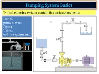
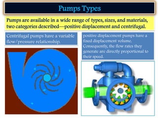
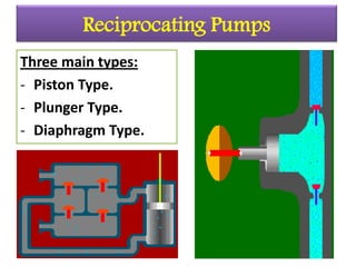
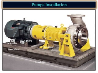
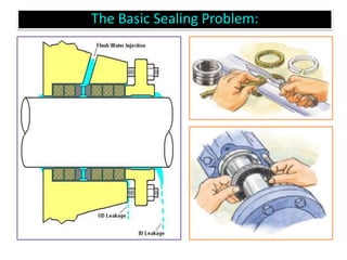
The document provides information on pump types, components, operation, and installation. It defines a pump as a mechanical device that transfers fluid from one point to another. Two main categories of pumps are described: positive displacement pumps that have a fixed volume and centrifugal pumps with a variable flow/pressure relationship. The document outlines the components and operation of common pump types like reciprocating, rotary, and centrifugal pumps. It also discusses selecting a pump based on system requirements, installing the pump properly, and connecting piping and valves.


![The amount of fluid power that a
system consumes is a product of head
and flow, according to this equation:
Fluid power = HQ (s.g.)
3,960
where
H = head (ft)
Q = flow rate (gallons per minute [gpm])
s.g. = specific gravity of the fluid
3,960 is a units conversion to state fluid
power in terms of horsepower
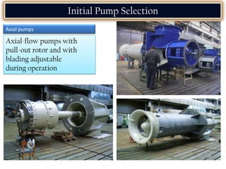
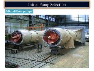
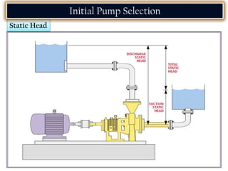
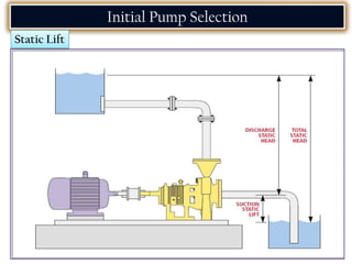
Initial Pump Selection
The operating point of centrifugal
pumps at which their efficiency is
highest is known as the best efficiency
point (BEP). Efficiencies range
widely, from 35% to more than 90%,
and they are a function of many
design characteristics](https://image.slidesharecdn.com/pumpinstallationandmaintenance-230130143217-57de2023/85/Pump-installation-and-Maintenance-pdf-41-320.jpg)


![Attack surfaces and attack tress[inform]](https://cdn.slidesharecdn.com/ss_thumbnails/lecture03-260108015941-a4dee53b-thumbnail.jpg?width=640&height=640&fit=bounds)


