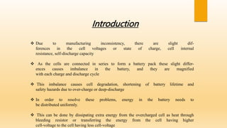
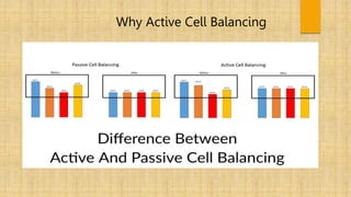
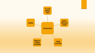
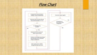
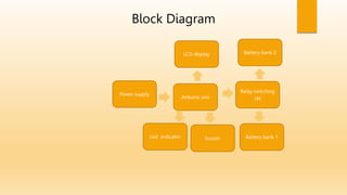
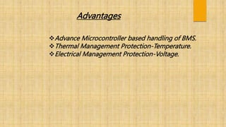
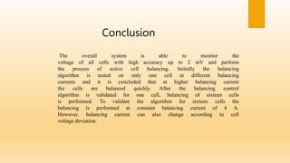
Cell Balancing techniques in
EV’s
Project By:
1. Vinayak Bhoir
2.Satyam Deokate
3.Umakant Pune
UNDER THE GUIDANCE OF
MRS. VARSHA SURWASE
VIDYA PRATISHTHAN'S KAMALNAYAN BAJAJ INSTITUTE OF ENGINEERING &
TECHNOLOGY
Abstract
Battery is the heart of electric vehicle and a way
of improving the battery life is to equalize the energy of its
cells. This can be done by either dissipating excess energy in the
form of heat (passive cell balancing) or charging the low voltage
cells through high voltage cells (active cell balancing)
Introduction
 Due to manufacturing inconsistency, there are slight dif-
ferences in the cell voltages or state of charge, cell internal
resistance, self-discharge capacity
 As the cells are connected in series to form a battery pack these slight differ-
ences causes imbalance in the battery, and they are magnified
with each charge and discharge cycle
 This imbalance causes cell degradation, shortening of battery lifetime and
safety hazards due to over-charge or deep-discharge
 In order to resolve these problems, energy in the battery needs to
be distributed uniformly.
 This can be done by dissipating extra energy from the overcharged cell as heat through
bleeding resistor or transferring the energy from the cell having higher
cell-voltage to the cell having less cell-voltage
Why Active Cell Balancing
Components
Li-ion
Battery
Pack
ESP32-
Microcon
troller
PWM
Controller
Digital to
Analog
Controller
Display
Flow Chart
Block Diagram
Arduino uno
Power supply
Relay switching
ckt
Led indicator Battery bank 1
buzzer
Battery bank 2
LCD display
Advantages
Advance Microcontroller based handling of BMS.
Thermal Management Protection-Temperature.
Electrical Management Protection-Voltage.
Conclusion
The overall system is able to monitor the
voltage of all cells with high accuracy up to 2 mV and perform
the process of active cell balancing. Initially the balancing
algorithm is tested on only one cell at different balancing
currents and it is concluded that at higher balancing current
the cells are balanced quickly. After the balancing control
algorithm is validated for one cell, balancing of sixteen cells
is performed. To validate the algorithm for sixteen cells the
balancing is performed at constant balancing current of 4 A.
However, balancing current can also change according to cell
voltage deviation.
Reference
 G. Ren, G. Ma, and N. Cong, “Review of electrical energy storage
system for vehicular applications,” Renewable and Sustainable Energy
Reviews, vol. 41, pp. 225-236, 2015.
 M.-Y. Kim, C.-H. Kim, J.-H. Kim, and G.-W. Moon, “A modularized
bms with an active cell balancing circuit for lithium-ion batteries in v2g
system,” in Vehicle Power and Propulsion Conference (VPPC), 2012 IEEE.
 L. Valda and K. Kosturik, “Comparison of li-ion active cell balancing
methods replacing passive cell balancer,” in 2015 International Confer-
ence on Applied Electronics (AE). IEEE, 2015, pp. 267-270.
THANK YOU

Cell Balancing techniques in EV’s 2.pptx

  • 1.
    Cell Balancing techniquesin EV’s Project By: 1. Vinayak Bhoir 2.Satyam Deokate 3.Umakant Pune UNDER THE GUIDANCE OF MRS. VARSHA SURWASE VIDYA PRATISHTHAN'S KAMALNAYAN BAJAJ INSTITUTE OF ENGINEERING & TECHNOLOGY
  • 2.
    Abstract Battery is theheart of electric vehicle and a way of improving the battery life is to equalize the energy of its cells. This can be done by either dissipating excess energy in the form of heat (passive cell balancing) or charging the low voltage cells through high voltage cells (active cell balancing)
  • 3.
    Introduction  Due tomanufacturing inconsistency, there are slight dif- ferences in the cell voltages or state of charge, cell internal resistance, self-discharge capacity  As the cells are connected in series to form a battery pack these slight differ- ences causes imbalance in the battery, and they are magnified with each charge and discharge cycle  This imbalance causes cell degradation, shortening of battery lifetime and safety hazards due to over-charge or deep-discharge  In order to resolve these problems, energy in the battery needs to be distributed uniformly.  This can be done by dissipating extra energy from the overcharged cell as heat through bleeding resistor or transferring the energy from the cell having higher cell-voltage to the cell having less cell-voltage
  • 4.
    Why Active CellBalancing
  • 5.
  • 6.
  • 7.
    Block Diagram Arduino uno Powersupply Relay switching ckt Led indicator Battery bank 1 buzzer Battery bank 2 LCD display
  • 8.
    Advantages Advance Microcontroller basedhandling of BMS. Thermal Management Protection-Temperature. Electrical Management Protection-Voltage.
  • 9.
    Conclusion The overall systemis able to monitor the voltage of all cells with high accuracy up to 2 mV and perform the process of active cell balancing. Initially the balancing algorithm is tested on only one cell at different balancing currents and it is concluded that at higher balancing current the cells are balanced quickly. After the balancing control algorithm is validated for one cell, balancing of sixteen cells is performed. To validate the algorithm for sixteen cells the balancing is performed at constant balancing current of 4 A. However, balancing current can also change according to cell voltage deviation.
  • 10.
    Reference  G. Ren,G. Ma, and N. Cong, “Review of electrical energy storage system for vehicular applications,” Renewable and Sustainable Energy Reviews, vol. 41, pp. 225-236, 2015.  M.-Y. Kim, C.-H. Kim, J.-H. Kim, and G.-W. Moon, “A modularized bms with an active cell balancing circuit for lithium-ion batteries in v2g system,” in Vehicle Power and Propulsion Conference (VPPC), 2012 IEEE.  L. Valda and K. Kosturik, “Comparison of li-ion active cell balancing methods replacing passive cell balancer,” in 2015 International Confer- ence on Applied Electronics (AE). IEEE, 2015, pp. 267-270.
  • 11.