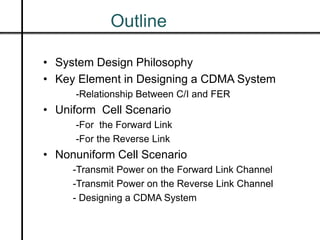
CDMA Cellular Radio Network
PRESENTED BY
Md Khanjahan Ali
Outline
• System Design Philosophy
• Key Element in Designing a CDMA System
-Relationship Between C/I and FER
• Uniform Cell Scenario
-For the Forward Link
-For the Reverse Link
• Nonuniform Cell Scenario
-Transmit Power on the Forward Link Channel
-Transmit Power on the Reverse Link Channel
- Designing a CDMA System
System Design Philosophy
• In TDMA system, capacity increase as elimination of
Interference from desire signal.
• In CDMA system, the capacity increase depend on
how much interference the desire signal can tolerate.
• In CDMA , All user share the same radio channel.If
one user take more power than it need, then other will
be suffer and capacity will be decreased.
• This presentation adresses how to tune The CDMA
cellular radio network in order to tolarate interference.
Key Element in Designing a CDMA System
• In analog and TDMA system ,the most importent key
element is C/I.
-Measured C/I : indicate the voice quality of system.
-Specified C/I : specified value for the system.
• Therefore field strength meters use to design TDMA.
• In CDMA all voice channels served by a single radio
channel.
-m-voice channel cell,
-1 is trafic channel and m-1 interference channel.
- C/I is hard to obtain by using a signal strength meter.
• The key element in designing a CDMA system are different
from Designin TDMA system.
Relationship Between C/I and FER
• In CDMA ,The key element Eb/Io which is related to FER (Frame
Error Rate).
• We can design CDMA On the basis of following equation.
where,
Eb= Energy/Bit, Io=Power/Herz.
Rb = Bit/sec, B = Bandwidth.
• Eb/Io always varies in order to meet a specified FER
• From Equation We can find a required (C/I) from Specified Eb/Io
• Have two different Requirement for C/I:
-(C/I)F for the forward link channel
-(C/I)R for the Reverse link channel













B
R
I
E
I
C b
o
b
Uniform Cell Scenario
For the Forward link Channel
• The C/I received at a mobile station A to the transmitted
powers of all cell sites:
home cell 2 adjacent cells 3 interim cells 6 distant cells
(I1) (I2,I3) (I4,I5,I6) (I7,I8,I9,I10,I11,I12)
• The relationship between of the three maximum
transmitted powers of the three cells is
1
4
1
4
1
3322
1
)633.2()2(
)1(
1
/





 







mm
m
IC
3
3
2
2
1
1
m
p
m
p
m
p

For the Reverse link
• The received C/I at the desired voice
channel can be expressed as:
• The worst-case scenario is when:
CmrCmrCm
C
IC
321 .)1(
/
1312 

321 13121
1
mrmrm 

1
/
1
321 1312 
IC
mrmrm
Nonuniform Cell Scenario
Transmitted Power on the Forward link Channels
• All the cell size are not the same in a nonuniform CDMA
system
• Consider only the three cells most affected by location of
three vehicles
• The (C/I)F Received at vehicle 1,2,3 Respectively:
1
4
333
4
222
4
111
4
11
11
)1(
)/(


IRmRmRm
R
IC F

 

2
4
333
4
111
4
222
4
22
22
)1(
)/(


IRmRmRm
R
IC F

 

3
4
222
4
111
4
333
4
33
33
)1(
)/(


IRmRmRm
R
IC F

 

Transmitted Power on the Forward link Channels
• Interference at cell site 1,2,3 respectively
• Under the physical condition ,the following relation have
to be held.
''
'
1
4
13313
4
1212
4
111
4
11
11
2')1(
)/(


IRmrRmrRm
R
IC R

 

4
23323
4
21121
4
222
4
22
22
''
'
')1(
)/( 



RmrRmrRm
R
IC R


4
32232
4
31131
4
333
4
33
33
''
'
')1(
)/( 



RmrRmrRm
R
IC R


1
)/(
1
,, 321 
RIC
mmm
Designing a CDMA system
• First have to check
whether all requirement
express above equation
are met with our
condition
• Then find the transmit
Power .
Thank You

CDMA cellular radio network

  • 1.
    CDMA Cellular RadioNetwork PRESENTED BY Md Khanjahan Ali
  • 2.
    Outline • System DesignPhilosophy • Key Element in Designing a CDMA System -Relationship Between C/I and FER • Uniform Cell Scenario -For the Forward Link -For the Reverse Link • Nonuniform Cell Scenario -Transmit Power on the Forward Link Channel -Transmit Power on the Reverse Link Channel - Designing a CDMA System
  • 3.
    System Design Philosophy •In TDMA system, capacity increase as elimination of Interference from desire signal. • In CDMA system, the capacity increase depend on how much interference the desire signal can tolerate. • In CDMA , All user share the same radio channel.If one user take more power than it need, then other will be suffer and capacity will be decreased. • This presentation adresses how to tune The CDMA cellular radio network in order to tolarate interference.
  • 4.
    Key Element inDesigning a CDMA System • In analog and TDMA system ,the most importent key element is C/I. -Measured C/I : indicate the voice quality of system. -Specified C/I : specified value for the system. • Therefore field strength meters use to design TDMA. • In CDMA all voice channels served by a single radio channel. -m-voice channel cell, -1 is trafic channel and m-1 interference channel. - C/I is hard to obtain by using a signal strength meter. • The key element in designing a CDMA system are different from Designin TDMA system.
  • 5.
    Relationship Between C/Iand FER • In CDMA ,The key element Eb/Io which is related to FER (Frame Error Rate). • We can design CDMA On the basis of following equation. where, Eb= Energy/Bit, Io=Power/Herz. Rb = Bit/sec, B = Bandwidth. • Eb/Io always varies in order to meet a specified FER • From Equation We can find a required (C/I) from Specified Eb/Io • Have two different Requirement for C/I: -(C/I)F for the forward link channel -(C/I)R for the Reverse link channel              B R I E I C b o b
  • 6.
    Uniform Cell Scenario Forthe Forward link Channel
  • 7.
    • The C/Ireceived at a mobile station A to the transmitted powers of all cell sites: home cell 2 adjacent cells 3 interim cells 6 distant cells (I1) (I2,I3) (I4,I5,I6) (I7,I8,I9,I10,I11,I12) • The relationship between of the three maximum transmitted powers of the three cells is 1 4 1 4 1 3322 1 )633.2()2( )1( 1 /               mm m IC 3 3 2 2 1 1 m p m p m p 
  • 8.
  • 9.
    • The receivedC/I at the desired voice channel can be expressed as: • The worst-case scenario is when: CmrCmrCm C IC 321 .)1( / 1312   321 13121 1 mrmrm   1 / 1 321 1312  IC mrmrm
  • 10.
    Nonuniform Cell Scenario TransmittedPower on the Forward link Channels
  • 11.
    • All thecell size are not the same in a nonuniform CDMA system • Consider only the three cells most affected by location of three vehicles • The (C/I)F Received at vehicle 1,2,3 Respectively: 1 4 333 4 222 4 111 4 11 11 )1( )/(   IRmRmRm R IC F     2 4 333 4 111 4 222 4 22 22 )1( )/(   IRmRmRm R IC F     3 4 222 4 111 4 333 4 33 33 )1( )/(   IRmRmRm R IC F    
  • 12.
    Transmitted Power onthe Forward link Channels
  • 13.
    • Interference atcell site 1,2,3 respectively • Under the physical condition ,the following relation have to be held. '' ' 1 4 13313 4 1212 4 111 4 11 11 2')1( )/(   IRmrRmrRm R IC R     4 23323 4 21121 4 222 4 22 22 '' ' ')1( )/(     RmrRmrRm R IC R   4 32232 4 31131 4 333 4 33 33 '' ' ')1( )/(     RmrRmrRm R IC R   1 )/( 1 ,, 321  RIC mmm
  • 14.
    Designing a CDMAsystem • First have to check whether all requirement express above equation are met with our condition • Then find the transmit Power .
  • 15.