This document provides guidance on designing, constructing and repairing concrete floors on ground. It discusses subgrade preparation and subbases, moisture control methods like vapor retarders, concrete mix design considerations, and techniques for achieving flat and level floors. Proper subgrade compaction and drainage, use of vapor retarders if needed, and achieving good consolidation of concrete are emphasized to obtain floors that perform well and have low maintenance costs. Thicker floors with adequate reinforcement can withstand heavier loads and reduce repairs over the life of the structure.

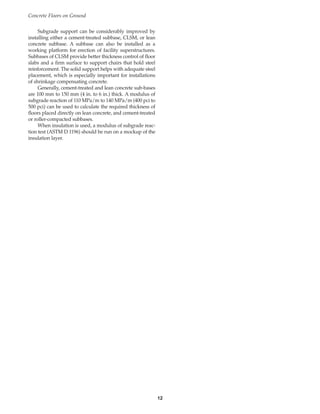
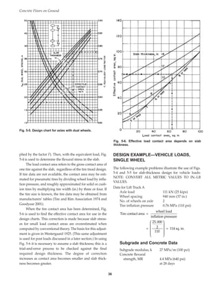
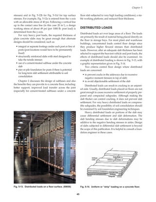
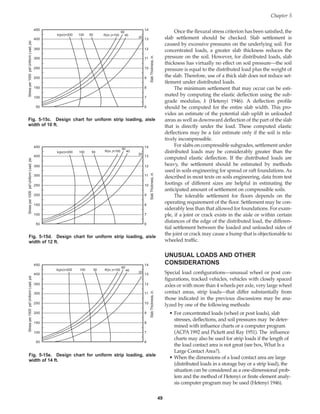
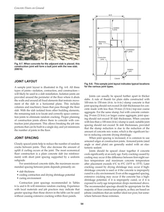
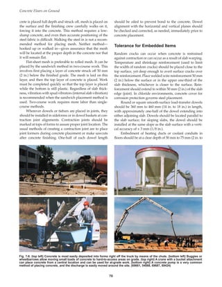
![The allowable soil bearing capacity is the maximum
pressure that can be permitted on foundation soil with
adequate safety against soil rupture or excessive settle-
ment. Allowable soil pressure may be based on:
• laboratory shear strength tests (of soil samples) such as
the direct shear test, triaxial compression test, or
unconfined compression test
• field tests such as the standard penetration test or cone
penetrometer test
• soil classification
• moisture-density-strength relationships (established by
conducting strength tests on soil specimens prepared
for moisture-density testing)
Beyond the allowable soil pressure is the ultimate
bearing capacity, the load per unit area (soil pressure) that
will produce failure by rupture of a supporting soil.
Another soil characteristic, compressibility of cohesive
soils, determines the amount of long-term settlement
under load. The usual method for predicting settlement is
based on conducting soil consolidation tests and determin-
ing the compression index for use in the settlement com-
putations. The compression index may be estimated by
correlation to the liquid limit of the soil.
A third measure of soil strength, Westergaard’s modu-
lus of subgrade reaction, k, is commonly used in design
procedures for concrete pavements and floors-on-grade
that are not structural elements in the building (floors not
supporting columns and load-bearing walls).
There is no reliable correlation between the three
measures of soil properties—modulus of subgrade reac-
tion, soil bearing capacity, and soil compressibility—
because they are measurements of entirely different char-
acteristics of a soil. The k-value used for floor-slab design
reflects the response of the subgrade under temporary
(elastic) conditions and small deflections, usually 1.25 mm
(0.05 in.) or less. Soil compressibility and bearing capacity
values (normally used to predict and limit differential set-
tlements between footings or parts of a foundation) reflect
total permanent (inelastic) subgrade deformations that
may be 20 to 40 (or more) times greater than the small
deflections on which k-values are based.
Substantial pavement research has shown that elastic
deflections and stresses of the slab can be predicted rea-
sonably well when using k-value to represent the subgrade
response. Consequently, the control of slab stresses based
on the subgrade k-value is a valid design procedure.
Although the k-value does not reflect the effect of
compressible soil layers at some depth in the subgrade, it
is the correct factor to use in design for wheel loads and
other concentrated loads because soil pressures under a
slab of adequate thickness are not excessive. However, if
heavy distributed loads will be applied to the floor, the
allowable soil pressure and the amount of settlement
should be estimated to determine if shear failure or exces-
sive settlement might occur.
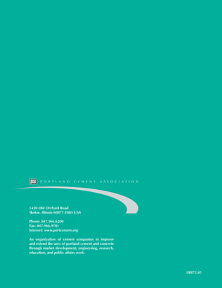
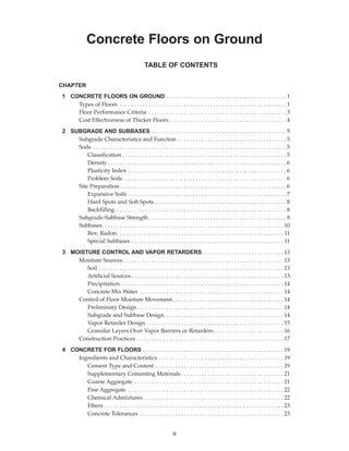
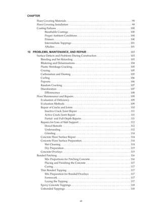
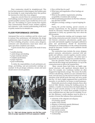
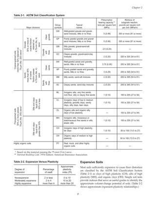
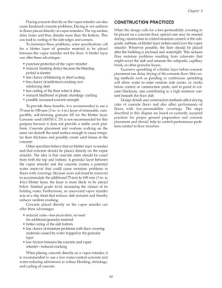
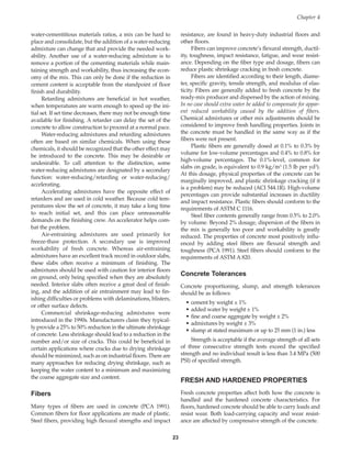
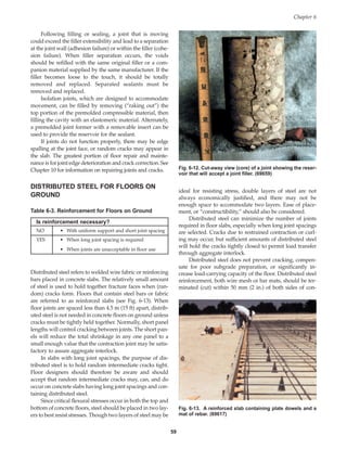
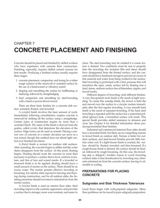
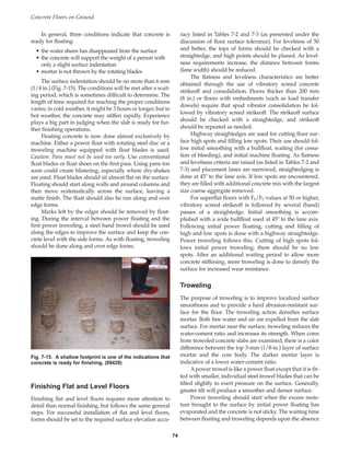
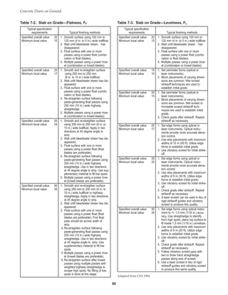
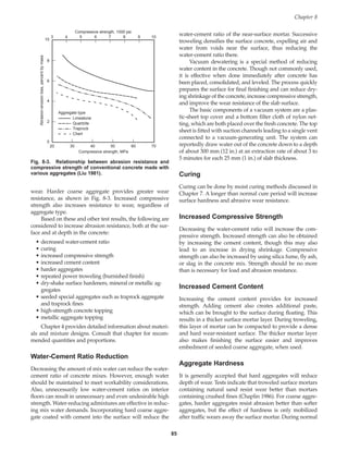
If there are no unusually adverse soil conditions, the
design analysis requires only the determination of the
strength of the subgrade in terms of k. The k-value is meas-
ured by plate-loading tests taken on top of the compacted
subgrade (or subbase, if used) as seen in Fig. 2-5. A gener-
al procedure for load testing is given in ASTM D 1196,
Standard Test Method for Nonrepetitive Static Plate Load Tests
of Soils and Flexible Pavement Components, for Use in
Evaluation and Design of Airport and Highway Pavements.
This method provides guidance in the field determination
of subgrade modulus with various plate diameters. Design
of Slabs on Grade (ACI 360R) is specifically oriented to the
determination of modulus of subgrade reaction using a
760-mm (30-in.) diameter plate and gives more detailed
information on test methods using this size plate. This
plate is loaded to a deflection not greater than 1.25 mm
(0.05 in.), and the k-value is computed by dividing the unit
load by the deflection obtained. A more economical test
using smaller plates (300 mm [12 in.]) that determines a
modified subgrade reaction modulus
is mentioned in ACI 360R. In each
case, the units of k are given in pres-
sure per length: MPa/m in the metric
system, or in in.-lb units, pounds per
square inch per inch, or psi per in. or,
as commonly expressed, pounds per
cubic inch (pci). The plate load test is
no longer commonly run in practice.
Instead, subgrade reaction values are
estimated from the California Bearing
Ratio or from the soil classification.
When plate-bearing tests are not per-
formed at the jobsite, the k-value can
be estimated from correlations such as
those shown in Table 2-3.
Chapter 2
9
Fig. 2-5. Testing to determine the modulus of subgrade reaction. (69652)
Book Contents
Publication List](https://image.slidesharecdn.com/eb075concretefloors-210419145726/85/Eb075-concrete-floors-19-320.jpg)
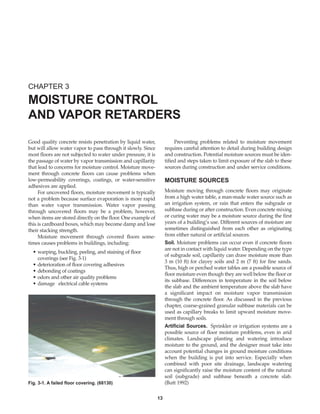
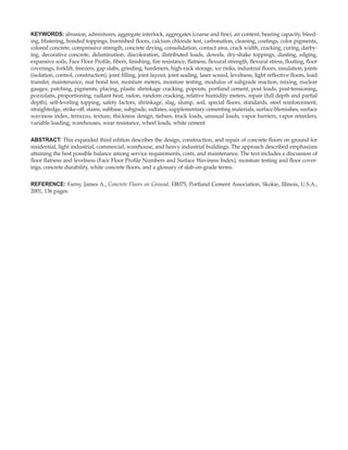
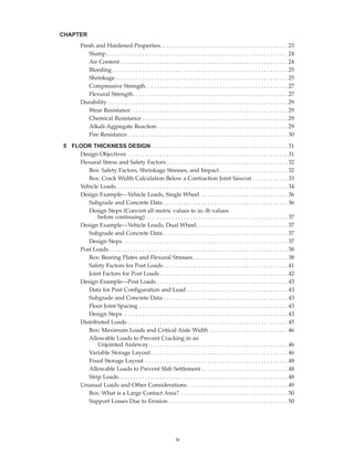
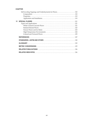
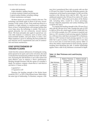
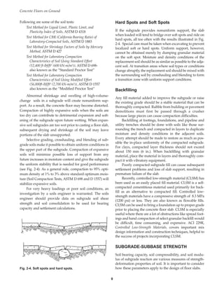
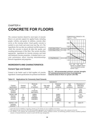
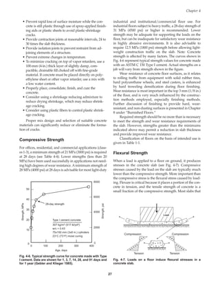
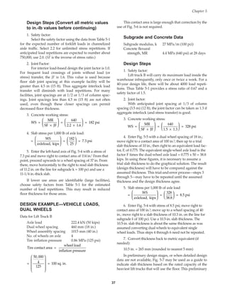
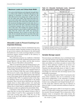
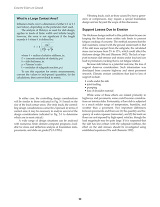
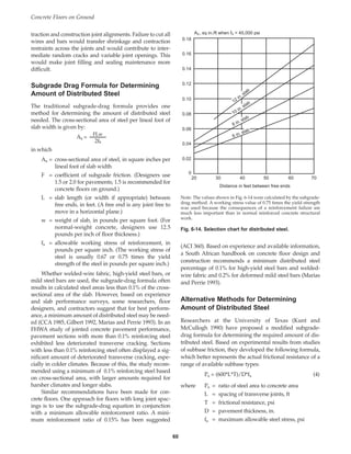
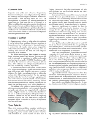
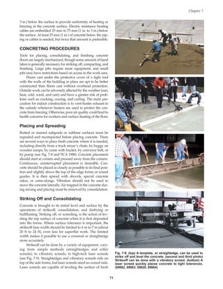
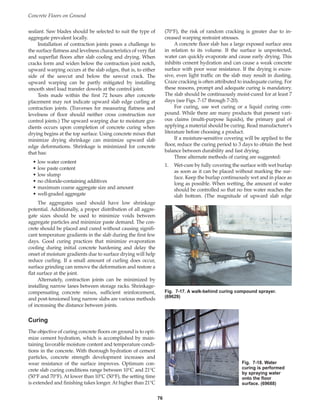
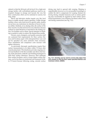
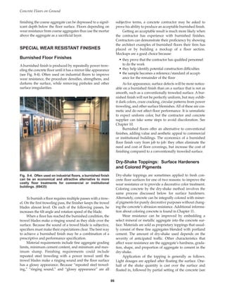
![A layer of open-graded, clean, compacted coarse
aggregate is usually needed as a capillary break when the
floor will be built on sandy soils or very fine soils (more
than 45% of the particles by weight pass the 75-micron
[No. 200] sieve). The capillary break usually consists of a
100-mm to 200-mm (4-in. to 8-in.) thick layer of 19-mm
(3/4-in.) washed, single-size aggregate (see Fig. 3-4). The
uniform aggregate size allows for air pockets between par-
ticles and reduces the upward movement of water. Gravel
is preferred to crushed stone when a vapor retarder is spec-
ified because the smoother particles are less likely to punc-
ture or tear the vapor retarder. Alternately, a geotextile fab-
ric can protect the vapor retarder from the aggregate parti-
cles. If the water table is far enough below the surface, cap-
illary water will not reach the underside of the slab and
there is little need for a capillary break.
Vapor Retarder Design
Floors on ground that are to receive any form of floor cover-
ing should be built with a vapor retarder below the slab (see
Fig. 3-5). A vapor retarder may also be needed in areas with
a high water table or other source of subsurface moisture.
Where some or all of the structure is located below the
water table, it may be necessary to use a vapor barrier
(rather than a vapor retarder), a membrane that virtually
stops moisture from passing through it. True vapor barri-
ers are products such as rugged reinforced membranes
that do not allow the passage of water vapor; they have
water-vapor transmission ratings of 0.00 perms (per sq m
per hr or per sq ft per hr) when tested in accordance with
ASTM E 96. These are generally multiple ply products that
may include polyethylene, reinforcing fibers or boards,
metallic foils, paper and/or bituminous materials (see Fig.
3-5). Proper performance of vapor barriers requires sealing
of all laps and strict adherence to the manufacturers’
recommendations.
Vapor retarders effectively minimize water vapor
transmission from the subbase through the slab, but are
not 100% effective in preventing water vapor passage.
Materials that have been used include 150-micrometer to
250-micrometer (6-mil to 10-mil) low-density polyethylene
sheets and medium- to high-density polyethylene films.
Some of these materials can be cross-laminated or rein-
forced. Because low-density polyethylene may deteriorate,
it is recommended to use high-density polyethylene. Vapor
retarders should meet the requirements of ASTM E 1745,
Standard Specification for Water Vapor Retarders Used in
Contact with Soil or Granular Fill Under Concrete Slabs. This
standard sets requirements for water vapor permeance
and establishes three grade classifications related to dura-
bility. Vapor retarders are required to have a permeance of
less than 0.3 perms as determined by ASTM E 96.
Vapor retarders, especially thinner ones, are suscepti-
ble to damage. While a 1.25-mm (50-mil) sheet of polyeth-
ylene will most likely resist any type of construction traffic,
a 100-micrometer (4-mil) sheet of polyethylene may be too
thin to remain intact and may not provide long-term dura-
bility. During placement, thin sheets can be torn. During
construction, they can be punctured when forms are
placed, when steel is set, when concrete is placed, or by
work traffic. As a result, both tensile strength and puncture
resistance are important. (The practice of intentionally
Chapter 3
15
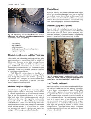
Fig. 3-4. Subbase materials are spread over the ground
(subgrade), then leveled and compacted to provide a
stable work surface that will not settle during or after
concrete placement. (69423)
Fig. 3-5. Vapor retarders and vapor barriers can be made
from many types of materials, but all serve the same
purpose: to reduce or eliminate the passage of water vapor
through concrete. (69683)
Book Contents
Publication List](https://image.slidesharecdn.com/eb075concretefloors-210419145726/85/Eb075-concrete-floors-25-320.jpg)

![cements are found in ASTM C 150, ASTM C 595, and
ASTM C 1157 (see Table 4-1).
If there are no special construction needs, a normal-use
portland or blended cement is regularly used, as these are
the most readily available. In ASTM C 150, this would be a
Type I, II, or I/II; in C 595, Types IS, IP, P, I(PM), and I(SM);
and in C 1157, Type GU. A single cement may simul-
taneously meet the requirements of more than one of these
classifications.
Sometimes, construction needs or service environment
dictate that a special cement type be used. Regarding con-
struction needs, a fairly common requirement is putting
the floor into service as quickly as possible. In this case, the
use of high early strength cement may be warranted.
Regarding service environment, aggressive exposures may
suggest the use of a special type of cement for durability.
For instance, high-sulfate environments can be due to soils
in certain regions of the country or can be the result of cer-
tain industrial processes. Sulfate-resistant cements are
available to meet the need of durable concrete in these
environments.
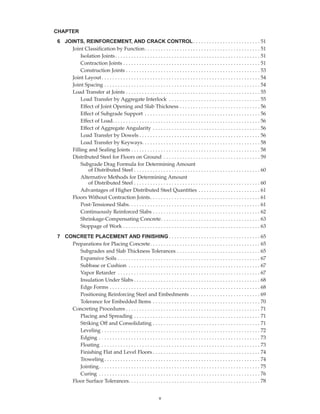
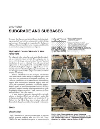
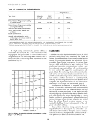
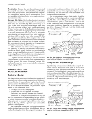
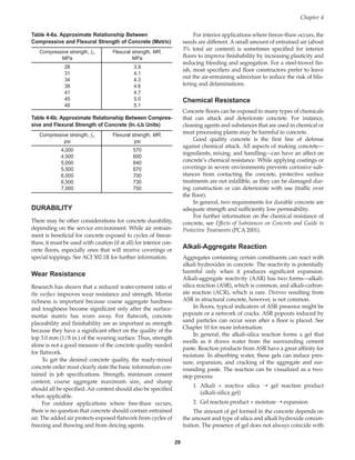
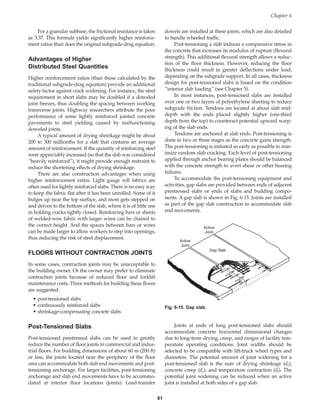
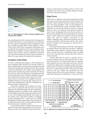
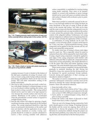
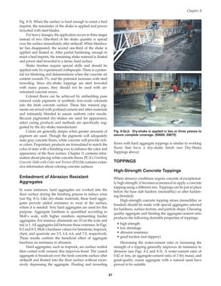
When sulfate exposures are encountered in natural
soils or in an industrial facility, cement should be chosen
for its ability to resist sulfate attack. The severity of the
exposure dictates the choice of cement that should be used
to provide sulfate resistance to the concrete. Cement
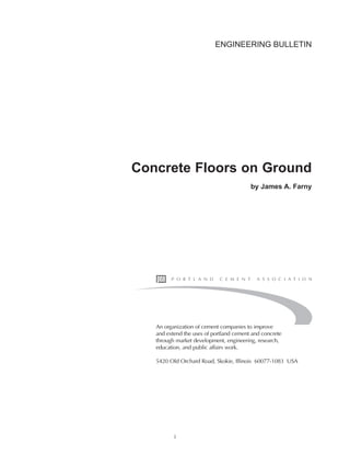
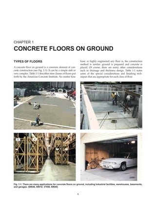
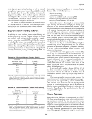
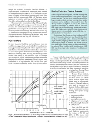
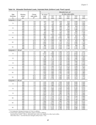
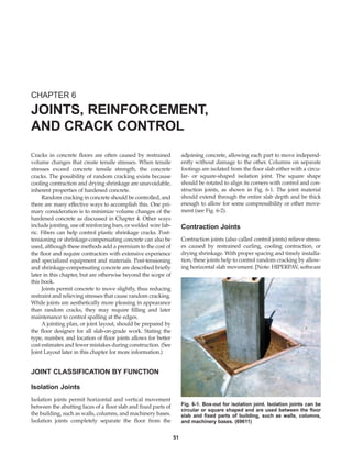
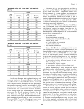
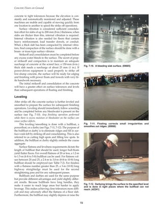
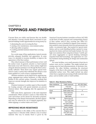
options for this purpose are shown in Table 4-2. Research
has shown that low water-cementitious materials ratios are
critical in the role of concrete durability in moderate or
severe sulfate environments (see Fig. 4-2).
With modern concrete technology, higher strengths
can now be obtained with less cement than in the past.
Where strength alone is the decisive criterion, less cement
means greater economy. Wear resistance of concrete, how-
Concrete Floors on Ground
20
Table 4-2. Requirements for Concrete Exposed to Sulfate-Containing Solutions*
Water-soluble sulfate Maximum water- Minimum
(SO4) in soil, Sulfate (SO4) cementitious compressive strength,
Sulfate exposure % by weight** in water, ppm** Cement type*** materials ratio MPa (psi)
Negligible 0.00–0.10 0–150 No restriction — —
II, IP(MS), IS(MS),
Moderate† 0.10–0.20 150–1500 P(MS), I(PM)(MS), 0.50 28 (4000)
I(SM)(MS), MS
Severe 0.20–2.00 1500–10,000 V, HS 0.45 31 (4500)
Very severe Over 2.00 Over 10,000 V, HS 0.40 34 (5000)
* Adapted from References [Kosmatka and Panarese 1992, U.S. BUREC 1975, and ACI 318]
** Test procedure: Method for Determining the Quantity of Soluble Sulfate in Solid (Soil or Rock) and Water Samples, Bureau of Reclamation, 1977.
ASTM is in the process of standardizing this method.
*** Cement Types II and V are specified in ASTM C 150, blended cements with the (MS)-suffix are specified in ASTM C 595, and the blended
cements designated as MS or HS are specified in ASTM C 1157. Pozzolans (ASTM C 618), slag (ASTM C 989), or silica fume (ASTM C 1240)
that have been determined by test or service record to improve sulfate resistance can also be used.
† Seawater.
Note: See (Kosmatka 1988) for alternatives when Type V or Type HS cement is not available. One option discussed is to use a cement and miner-
al admixture combination that has a maximum expansion of 0.10% at one year when tested according to ASTM C 1012, Test Method for Length
Change of Hydraulic-Cement Mortars Exposed to a Sulfate Solution. Another option is to reduce the water to cementitious materials ratio to 0.35 or less.
0.3 0.4 0.5 0.6 0.7 0.8
1.0
2.0
3.0
4.0
5.0
Visual
rating
Water-cement ratio by mass
Type I
Type II
TypeV
Rating:
1.0 = no deterioration
5.0 = severe deterioration
Fig. 4-2. (top) Both the cement type and the water-cement
ratio affect concrete’s ability to resist sulfate environments.
(bottom) Beams in sulfate-soil test plot with durability
illustrated in top graph. (66900)
Book Contents
Publication List](https://image.slidesharecdn.com/eb075concretefloors-210419145726/85/Eb075-concrete-floors-30-320.jpg)
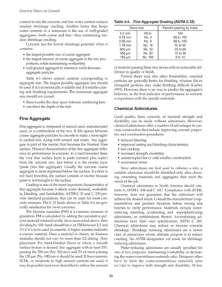
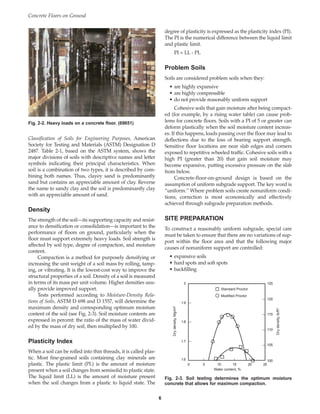
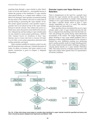
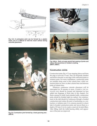
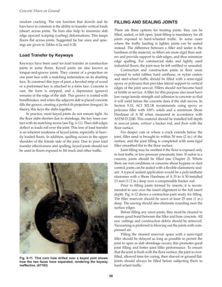
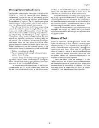
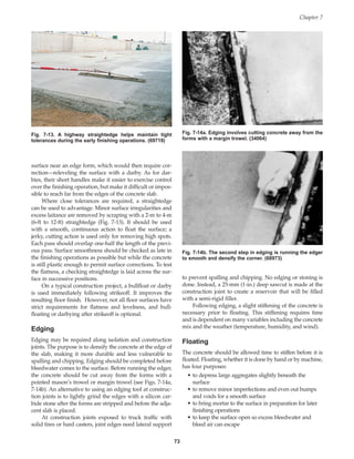
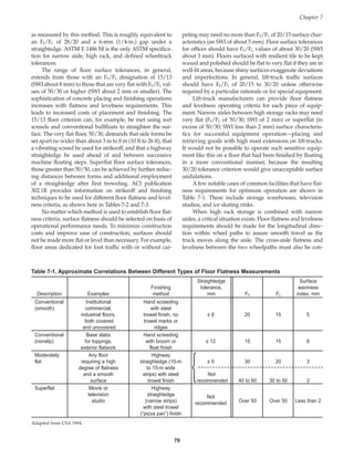
![Floor class* Surface traffic Slab surface
28-day compressive strength Maximum slump**
MPa psi mm in.
1 foot exposed 21.0 3000 125 5
2 covered 21.0 3000 125 5
3 exposed 28.0 4000 125 5
3 covered 21.0 3000 125 5
4 light vehicle exposed 28.0 4000 125 5
4 covered 24.5 3500 125 5
5 soft solid wheels exposed 31.5§§ 4500§§ 75 3
6 hard wheels no† 35.0§§ 5000§§ 75 3
6 hardener† 31.5 4500 75 3
7 base 28.0§§ 4000§§ 125 5
7 topping 35.0+ 5000+ 75 3
8 as for Class 4-6 base 28.0+§§ 4000+§§ 125 5
8 topping††, § 35.0+ 5000+ 75 3
9 superflat†† 31.5§§ 4500§§ 75 3
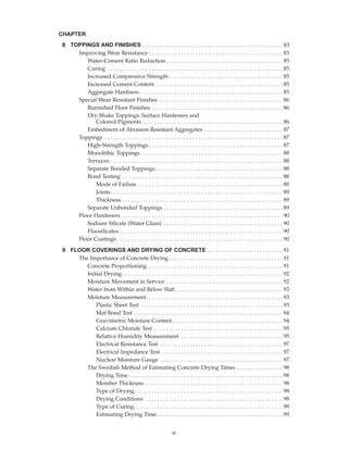
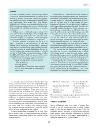
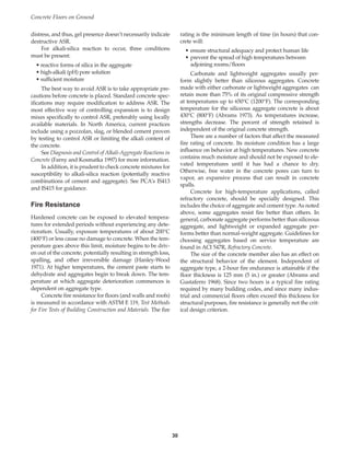
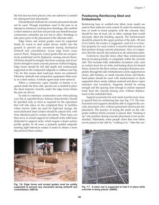
Slump
Excessive water used to produce high slump is a primary
cause of poor floor performance, as it leads to bleeding,
segregation, and increased drying shrinkage. If a finished
floor is to be level, uniform in appearance, and wear resist-
ant, all batches placed in the floor must have nearly the
same slump and must meet specification criteria.
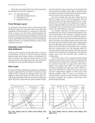
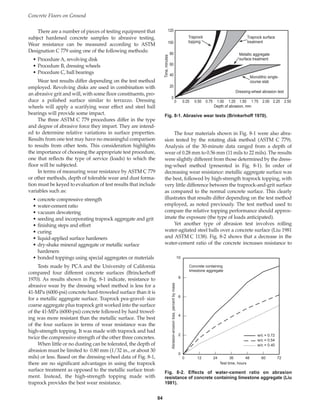
Low-slump (50 mm to 100 mm [2 in. to 4 in.]) concrete
flatwork is routinely struck off with mechanical equipment
like vibratory screeds. Typically, using such equipment for
floor work facilitates concrete consolidation, requiring less
water to be added at the jobsite, which ultimately results in
improved wear resistance of the surface. Low-slump con-
crete (see Fig. 4-3) helps to:
• reduce finishing time
• reduce cracking
• minimize surface defects
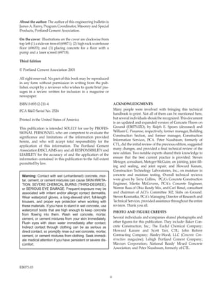
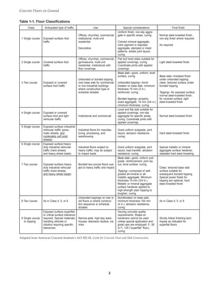
Recommended strengths and slumps for each ACI
class of floor are given in Table 4-5, adapted from ACI
302.1R. This slump limit is the same whether or not the
concrete contains chemical admixtures (superplasticizers
or normal water-reducing admixtures). Table 1-1 defines
all nine floor classes.
Air Content
Concrete for floors is usually not air entrained. A small
amount of entrained air is sometimes useful for concrete
floors because it reduces bleeding and increases plasticity.
A total air content (including both entrapped and
entrained air) of 2% to 3% is suggested. Concrete that will
be exposed to cycles of freezing and thawing and the appli-
cation of deicer chemicals requires a greater total air con-
tent—about 5% to 8% depending upon maximum size of
aggregate—to ensure resistance to scaling. For most floors
discussed in this publication, the maximum size aggregate
used will be between 9.5 mm and 37.5 mm [3/8 in. and 1-
Concrete Floors on Ground
24
Table 4-5. Recommended Strength and Slump for Floors
* Refer to Table 1-1 for floor class definitions.
** Target slumps should be 25 mm (1 in.) less than the maximum shown to allow for mix variation. Some floor classes allow up to 125-mm
(5-in.) slump, but lower slumps will result in less shrinkage, less curling, and other desirable properties.
† Metallic or mineral aggregate surface hardener.
†† The strength required will depend on the severity of usage.
§ Maximum aggregate size not greater than one-quarter the thickness of unbonded topping.
§§ Minimum 28-day flexural strength of 4 MPa (600 psi) (solid and hard wheels include heavy vehicle loading).
Fig. 4-3. Low- to moderate-slump concrete alleviates many
concerns associated with concrete floor placement and
finishing. (44485)
Book Contents
Publication List](https://image.slidesharecdn.com/eb075concretefloors-210419145726/85/Eb075-concrete-floors-34-320.jpg)
![1/2 in.]. However, it should be recognized that floating
and troweling, depending on finishing intensity, may
remove a significant amount (or all) of the entrained air
from the concrete mortar at the surface, severely impairing
freeze-thaw durability.
Whereas minimum air contents are well established
for durability (resistance to freeze-thaw or deicer attack),
there is a reason to consider setting a maximum: when
floor finishing operations include steel troweling. A maxi-
mum total air content of 3% has been established to reduce
the possibility of blistering. This occurs because steel trow-
els can seal the surface and trap air pockets beneath it,
especially when monolithic surface treatments are used.
Air content is chosen based on the needs of construc-
tion (ease of placement) and service environment (expo-
sure). The air content of the fresh concrete must be tested if
compliance with specifications is mandatory. Though test-
ing is recommended, it is not always performed on small-
er projects. Regardless of project specifications, if the floor will
be subjected to traffic, total air content should be measured
at the point of placement to verify compliance with the
specified air content. Unintentionally entrained air might
push the total air content above an acceptable level. Dry-
shake surfaces, especially, are at risk of blistering if the total
air content exceeds 3%.
Testing can be done using a pressure air meter (see Fig.
4-4) or a volumetric meter. Building codes and standards
indicate air content testing frequency, which is at least one
test daily. Only a qualified inspector should run an air test
for verifying conformance to specifications.
Whenever entrained air is used in concrete that will
receive a steel trowel finish, precautions must be taken to
prevent surface blistering. Air-entrained concrete bleeds
more slowly than non-air-entrained concrete, so the sur-
face may appear ready for floating and troweling while the
underlying concrete is still bleeding or plastic and releas-
ing air. If finishers seal the surface by troweling before
bleeding has ceased, blisters can form below a dense trow-
eled skin of mortar about 3 mm (1/8 in.) thick. Blisters
form late in the finishing process, after floating and the first
troweling.
To avoid blistering, place, strike off, and float the con-
crete as rapidly as possible without working up an exces-
sive layer of cement paste. Keep the float blades flat in ini-
tial floating to avoid densifying the surface too early. After
these operations are completed, delay further finishing as
long as possible by covering the surface with polyethylene
or otherwise protecting it from evaporation.
If these measures do not prevent blistering, avoid
using an air-entraining admixture in the concrete.
Do not use air-entrained concrete for floors that will
receive an application of dry-shake surface hardener.
These products require some moisture at the slab surface
so they can be thoroughly worked in. Because the en-
trained air slows bleeding, needed moisture may not be
present, and blistering or delamination of the hardened
surface is more likely.
Bleeding
In concrete construction, bleeding is the development of a
layer of surface water caused by the settling of solid parti-
cles (cement and aggregate) and the simultaneous upward
migration of water (Fig. 4-5). Some bleeding is normal and
helps to control plastic shrinkage cracking, but excessive
bleeding increases the water-cement ratio near the surface,
particularly if finishing operations take place while bleed-
water is present. This may result in a weak surface with
poor durability (Kosmatka 1994).
The amount and rate of bleeding increases with high-
er initial water content and thicker floors. The following
means can be used to reduce bleeding:
• properly graded aggregate
• supplementary cementitious materials
• finer cements
• certain chemical admixtures
• air entrainment
Shrinkage
Cracking can be the result of one or a combination of fac-
tors such as drying shrinkage, thermal contraction,
Chapter 4
25
Fig. 4-4. A pressure meter is the most common way of
checking the air content of a fresh concrete mixture. (66113)
Book Contents
Publication List](https://image.slidesharecdn.com/eb075concretefloors-210419145726/85/Eb075-concrete-floors-35-320.jpg)
![restraint (external or internal) to shortening, subgrade set-
tlement, and applied loads. Installing joints in concrete
floors forces cracks to occur in places where they are incon-
spicuous and thus controls random cracking.
Cracks that occur before hardening are usually the
result of settlement within the concrete mass, or shrinkage
of the surface caused by rapid loss of water while the con-
crete is still plastic. These are referred to as plastic-shrink-
age cracks.
As the concrete settles or subsides, cracks may devel-
op over embedded items, such as reinforcing steel, or adja-
cent to edges where it contacts forms or hardened concrete.
These cracks are referred to as settlement cracks.
Settlement cracking results from insufficient consolidation
(vibration), high slumps (overly wet concrete), or a lack of
adequate cover over embedded items.
Plastic-shrinkage cracks are relatively short cracks that
may occur before final finishing on days when one or more
of the following conditions exist; wind, low humidity, and
high temperature. Under these conditions, surface mois-
ture evaporates faster than it can be replaced by rising
bleedwater. As a result, the surface of the concrete sets
before lower portions of the slab. As the surface hardens it
begins to shrink more than the concrete below, allowing
plastic shrinkage cracks to develop in the slab surface.
Plastic shrinkage cracks often penetrate to mid-depth of a
slab. They vary in length and are usually parallel to each
other, spaced from a few centimeters (inches) up to 3 m (10
ft) apart.
Cracks that occur after hardening are usually the
result of drying shrinkage, thermal contraction, or sub-
grade settlement. After hardening, concrete begins to dry
and shrink as a result of water leaving the system. For
small, unrestrained concrete specimens (cylinders), shrink-
age (strain) has been measured at 500 to 800 millionths (at
50% relative humidity and 23°C [73°F])(Hanson 1968).
“Real” concrete shrinks less. A floor (which is retrained by
the subgrade) typically will be at 80% to 95% relative
humidity so the shrinkage is actually closer to 100 to 300
millionths.
To accommodate shrinkage and control the location of
cracks, joints are placed at regular intervals. Experience has
shown that contraction joints (induced cracks) should be
spaced at a distance from about 24 to 30 times the slab
thickness. This is equivalent to 5-m to 6 -m (17-ft to 20-ft)
intervals in each direction in 200-mm (8-in.) thick unrein-
forced concrete slabs on grade. If reinforcement is added,
and if intermediate random joints are acceptable, longer
joint spacings can be used. See Tables 6-1a and b for other
slab thicknesses and corresponding joint spacings.
The major factor influencing the drying shrinkage of
concrete is the total water content. As the concrete’s water
content increases, the amount of shrinkage increases pro-
portionally. Large increases in the sand content and signifi-
cant reductions in the size of the coarse aggregate increase
shrinkage because total water is increased and because
smaller size coarse aggregates provide less internal restraint
to shrinkage. Use of high-shrinkage aggregates and calcium
chloride admixtures also increase shrinkage. Some chemi-
cal admixtures complying with ASTM C 494 can increase
shrinkage. Within the range of practical concrete mixes—
280 to 445 kg/m3 cement content (470 to 750 lb/yd3, for-
merly referred to as “5- to 8-bag” mixes)—increases in
cement content have little to no effect on shrinkage as long
as the water requirement is not increased significantly.
Silica fume can make highly cohesive, sticky concrete,
with little bleeding capacity. With little or no bleedwater on
the surface, silica fume concrete is prone to plastic shrink-
age cracking on hot, windy days. Fogging the air above the
concrete and erecting windshades reduce the risk of plastic
shrinkage cracking.
Concrete has a coefficient of thermal expansion and
contraction of about 0.0000010 mm/mm/°C (0.0000055 in.
per in. per °F). Concrete placed during hot midday tem-
peratures will contract as it cools during the night. A 22°C
(40°F) drop in temperature between day and night—not
uncommon in some areas—would cause about 0.8 mm
(1/32 in.) of contraction in a 3-m (10-ft) length of concrete,
sufficient to cause cracking if the concrete is restrained.
Thermal expansion can also cause cracking.
Cracking in concrete slabs on grade of correct thick-
ness for the intended use can be reduced significantly or
eliminated by observing the following practices:
• Use proper subgrade preparation, including uniform
support and proper subbase material with adequate
moisture content.
• Minimize the mix water content by maximizing the
size and amount of coarse aggregate and by using
low-shrinkage aggregate.
• Use the lowest amount of mix water required for
workability; do not permit overly wet consistencies.
• Avoid calcium chloride admixtures.
Concrete Floors on Ground
26
Fig. 4-5. Bleeding brings water to the concrete surface.
(P29992)
Book Contents
Publication List](https://image.slidesharecdn.com/eb075concretefloors-210419145726/85/Eb075-concrete-floors-36-320.jpg)
![fail do so as a result of failure in flexure. Consequently, the
flexural stress and the flexural strength (modulus of rupture) of
the concrete are used in floor design to determine slab thickness.
Flexural strength is determined by modulus of rupture
(MOR or MR) tests in accordance with ASTM C 78, Flexural
Strength of Concrete (Using Simple Beam with Third-Point
Loading) (see Fig. 4-8). Usually the 28-day strength is select-
ed as the design strength for floors. This is generally con-
servative since the concrete continues to gain strength after
28 days. It may not be conservative when early-age con-
struction loading occurs.
There are some difficulties associated with flexural
strength testing. The test specimens are large, so they are
somewhat difficult to handle. The measurement of flexur-
al strength is quite sensitive to variations in test specimens
and procedures, more so than compressive strength test-
ing. Compressive strength cylinders (see Fig. 4-8) are easi-
er to make and move, and are less prone to damage than
flexural strength specimens. This is an important consider-
ation for specimens made at the jobsite that will have to be
transported to the lab for testing. For these reasons, a rela-
tionship is developed between flexural strength and com-
pressive strength by laboratory testing. Compressive
strength test results can then be used to estimate the flex-
ural strength by the formula:
MR = modulus of rupture or flexural strength,
in MPa or psi
fc = compressive strength, in MPa or psi
k (metric) = constant, usually between 0.7 (for
rounded aggregate) and 0.8 (for crushed
aggregate)
k (in.-lb) = constant, usually 9 to 11
Approximate correlations between compressive and
flexural concrete strength (for the case where k = approx.
0.74, metric [k = 9 in in.-lb units]) are listed in Table 4-6a, b.
Evidence of the relationship between compressive
strength and square root of the flexural strength is seen
graphically in Fig. 4-8, which shows long-term data for a
number of concrete mixtures.
MR k f
= c
Concrete Floors on Ground
28
Square root of (MPa) compressive strength
Square root of (psi) compressive strength
Modulus
of
rupture,
MPa
Modulus
of
rupture,
psi
Standard moist-cured cylinders,
150 x 300 mm (6 x 12 in.) nominal
Ages from 1 day to 5 years
20
0 40 80
60 120
100
6
1000
900
800
700
600
500
400
300
200
100
0
5
4
3
2
1
0
0 1 2 3 4 5 6 7 8 9 10
Fig. 4-8. (top) Third-point loading tests measure the flexural
strength of concrete beam specimens in the lab or in the
field with a portable flexural strength tester (shown here).
Results from compressive strength tests of cylinders are
correlated with flexural strength, useful in the quality con-
trol of concrete for floors. (middle) Companion beam and
cylinder samples can be made and tested to deter-mine the
relationship between flexural and compressive strengths.
(bottom) Long-term data show that compressive strength is
proportional to the square root of flexural strength
(measured by third-point loading) over a wide range of
strength levels (Wood 1992). (69684, 69653)
Book Contents
Publication List](https://image.slidesharecdn.com/eb075concretefloors-210419145726/85/Eb075-concrete-floors-38-320.jpg)
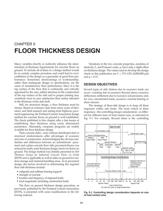
![titions (most important), shrinkage stresses, and impact
(see Safety Factors, Shrinkage Stresses, and Impact).
Appropriate safety factors for static loads, either con-
centrated or distributed, are not well established by expe-
rience or research. The designer should give careful con-
sideration to specific design conditions and performance
requirements and determine performance characteristics
of slabs under similar loading conditions.
Slab stresses for vehicle and post loads were deter-
mined by the use of a computer program with appropriate
modifications in load contact area (Packard 1967). The flex-
ural stresses indicated in the design charts are those at the
interior of a slab, assuming that the load is applied at some
distance from any free edge. For loads applied at or near
free slab edges, calculated flexural stresses are about 50% to
60% greater than those for interior load positions.* When
load transfer occurs across joints (either by dowels or aggre-
gate interlock), flexural stresses at the edge are reduced.
This stress reduction depends on stress transfer efficiency.
Because flexural stresses are 50% to 60% greater at slab
edges without adequate load transfer, slab thickness
should be increased at undoweled butt joints, whether the
joints are at the floor periphery or at interior locations. The
thickened slab compensates for the absence of load trans-
fer and keeps flexural stresses at these edges within safe
limits. See Vehicle Loads (this chapter) for guidelines on
thickening slabs.
For butt-type construction joints with dowel load trans-
fer, load-deflection transfer efficiencies are generally 85% or
better but the corresponding load-stress transfer efficiencies
(calculated) are only about 30% (note: the deflection and
stress load transfer efficiency are not the same). Slab thick-
ening aimed at maintaining tolerable flexural stresses is gen-
erally not needed for doweled joints. Instead, the working
stress is adjusted to accommodate edge stress effects. This is
illustrated in the following paragraph.
The slab thickness design charts used in this publica-
tion were developed for interior-of-slab load locations.
However, the same charts can be used for joints without
significant stress transfer efficiency that are subjected to
moving loads. Effects of edge stresses are accounted for by
adjusting the working stress (WS), using an appropriate
joint factor (JF) based on the higher flexural stresses at
loaded edges. For example, for a modulus of rupture of 3.9
MPa (560 psi), using a safety factor (SF) of 2.2 for interior
load location will provide a working stress of 1.8 MPa (255
psi) (see 5-1 and its accompanying discussion of allowable
number of load applications). For edge loads, the SF is
adjusted by a joint factor of 1.6 (60% higher than for the
interior load condition) to account for the higher concrete
flexural stresses at the edge. Thus the allowable WS is
lower: 3.9/(2.2 x 1.6) = 1.1 MPa [560/(2.2 x 1.6) = 160 psi].
When joint load transfer (and thus stress transfer) can be
assured—for example, by good aggregate interlock or by
dowels—the adjustment to the working stress for frequent
loadings is not as great. However, the designer is cautioned
that slab contraction caused by cooling and drying may
produce control joint cracks that are too wide to permit
aggregate interlock load transfer (Tabatabuie, Barenberg,
and Smith 1979).
Aggregate interlock load transfer efficiency decreases
significantly as the crack widens with time. Crack width
depends on the amount of slab contraction and on joint
spacings.All cracks are affected, whether they occur beneath
contraction joint sawcuts, strip inserts, or at random. The
magnitude of contraction depends on concrete placement
temperatures relative to operating floor temperatures and
on concrete drying shrinkage. Crack width should not exceed
0.89 mm (0.035 in.) if aggregate interlock is to remain effective
(Colley and Humphrey 1967). For thicker floors, aggregate
interlock may be effective even at wider joint openings.
The effects of concrete volume change on contraction
joint crack width are illustrated by the example provided
in the box, Crack Width Calculation Below a Contraction
Joint Sawcut. The coefficient of expansion of concrete is the
change in length per unit length with changes in tempera-
ture. A typical value for the coefficient of expansion of con-
crete is 9.9 x 10⁻⁶/°C (5.5 x 10⁻⁶/°F).
The slab described in the example in the box (Crack
Width Calculation) would not have effective load transfer
Chapter 5
33
*Analysis of concrete flexural stresses using the ILLI SLAB finite element
computer program show that edge stresses for free edge loads and interi-
or slab loads range from 50% to 60% greater when compared to interior
slab stresses. Calculations were made for lift truck and axle wheel spac-
ings of 910 mm and 1220 mm (36 in. and 48 in.), respectively, and a range
of (radius of relative stiffness) from 510 mm to 1520 mm (20 in. to 60 in.).
Crack Width Calculation Below a
Contraction Joint Sawcut
Joint spacing = 4.575 m = 4575 mm* (15 ft)
Temperature drop (from placing concrete to floor
operation) = 11.1°C (20°F)
Long term drying shrinkage = 200 millionths
∆ LT Contraction due to temperature =
0.0000099 ∆ T (°C) L (mm)
∆ LD Contraction due to drying =
(200 ÷ 1,000,000) L (mm)
Total crack width (in mm) = ∆ LT + ∆ LD
= 0.502 + 0.915 = 1.417 mm, say 1.42 mm
∆ LT Contraction due to temperature =
0.0000055 ∆ T (°F) L (in.)
∆ LD Contraction due to drying = (200 ÷ 1,000,000) L (in.)
Total crack width (in.) = ∆ LT + ∆ LD
= 0.0198 + 0.036 = 0.0558 in., say 0.056 in.
*The convention on metric plans is to use mm for all length meas-
urements to avoid confusion. In this publication, however, length
measurements in meters are also used.
= × × ×
( )+
× ×
0 0000099 20 15 12
200
1 000 000
15 12
.
, ,
= × ×
( )+
×
0 0000099 11 1 4575
200
1 000 000
4575
. .
, ,
Book Contents
Publication List](https://image.slidesharecdn.com/eb075concretefloors-210419145726/85/Eb075-concrete-floors-43-320.jpg)
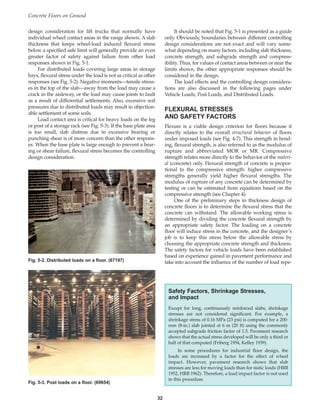
![Bearing stress is significantly less than allowable bearing
stress.
So the computed shear stress for the bearing area is:
Computed shear stress for edge load:
Computed shear stress for corner load:
=
post load
slab depth 0.5 load periphery + slab depth
=
13,000
10.5 0.5 32 + 10.5
= 47 psi
× ×
( ) ( )
[ ]
× ×
( ) ( )
[ ]
=
post load
slab depth 0.75 load periphery + 2 slab depth
=
13,000
10.5 0.75 32 + 2 10.5
= 28 psi
× ×
( ) ×
( )
[ ]
× ×
( ) ×
( )
[ ]
=
13,000
10.5 [32 + 42]
= 17 psi
×
Allowable shear stress
= 0.27 = 0.27 640 = 173 psi
Computed shear stress =
post load
shear area
Computed shear stress for interior load
Load periphery is four times the square root of
=
post load
slab thickness load periphery + 4 slab thickness
Load periphery is four times the square root of bearing
area — here :
= 4 64 = 32 in.
× ×
× ×
( )
[ ]
MR
Calculated corner, edge, and interior shear stresses are
significantly less than allowable concrete shear stresses.
Convert thickness of slab back to metric (if needed):
10.5 in. = 265 mm
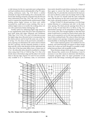
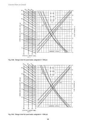
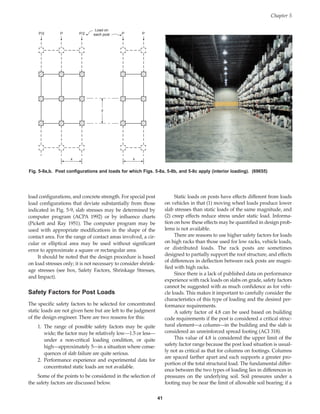
Alternately, the floor thickness design for post loads
located parallel to and along a slab edge or joint with no
load transfer may be accomplished through the use of Figs.
5-10 through 5-12. Post load positions are shown in Fig.
5-10. Figs. 5-11a through 5-11d were based on analysis of
the effect of post loading along slab edges using the JSLAB
finite element analysis program. Figs. 5-11a, b, and c are
for stresses at slab bottom. Fig. 5-11d is for stresses at slab
top surface (negative bending stress). The following inputs
(in.-lb) were used for the analysis:
E = 4 million psi
Poisson’s ratio = 0.15
Slab dimensions = 17 ft by 17 ft
Post contact area = 10 in.2
Modulus of subgrade reaction, k, of 50, 100 and 200 pci
Four spacings of post loads in each direction
Joint factors are not included as the design is based on
free edge loading. Taking an example, for post load spac-
ings of y = 20 in., x = 60 in., and k = 100 pci, use Fig. 5-11a.
(For other y-dimensions, use Figs. 5-11b, c, or d.) With
roughly 28-psi stress per 1000 lb post load for the example
shown, move horizontally to the x = 60 in. line, drop a ver-
tical line to the k = 100 pci curve, then move horizontally to
the right axis to determine a slab thickness of 6.4 in.
For a contact area other than 10 in.2 a correction factor
is used to account for the beneficial effect of a larger bear-
ing plate under the post. Correction factors are provided in
Fig. 5-12a for Figs. 5-11a, b, and c (for slab bottom surface
Concrete Floors on Ground
44
100
80
60
40
20
0 20 40 60 80 100
Allowable Stress per 1000 lb Post Load, psi
Design
Stress
per
1000
lb
Post
Load,
psi
Contact Area (sq in.) = 80 40 20 10
100
80
60
40
20
0 20 40 60 80 100
Allowable Stress per 1000 lb Post Load, psi
Design
Stress
per
1000
lb
Post
Load,
psi
Contact Area (sq in.) = 80 40 20 10
Fig. 5-12a. Design stress depends on allowable stress and
contact area for the case of tensile stress at the slab bottom
for slab edge post loads.
Fig. 5-12b. Design stress depends on allowable stress and
contact area for the case of tensile stress at the slab top for
slab edge post loads.
Book Contents
Publication List](https://image.slidesharecdn.com/eb075concretefloors-210419145726/85/Eb075-concrete-floors-54-320.jpg)
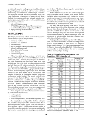
![sponsored by the FHWA, can be used to evaluate cracking
potential.]
Contraction joints can be made in several ways:
• sawing a continuous straight slot in semi-hardened
(slightly soft) concrete with special early-cut saws
• sawing a continuous straight slot in the hardened
concrete
• hand grooving fresh concrete during finishing (not
practical for floors more than 100 mm [4 in.] thick)
• installing premolded plastic or metal inserts during
placing and finishing
Whether joints are made by hand grooving, insert-
ing premolded materials, or sawing slightly soft or hard-
ened concrete, they should usually extend into the slab to
a depth of one-fourth the slab thickness (see Figs. 6-3, 6-4,
and 6-5). The objective is to form a plane of weakness in the
slab so that the crack will occur along that line and no-
where else, as shown in Fig. 6-3.
When floors carry vehicular traffic and joint fillers are
needed, saw cutting the joint is the only acceptable
method. Hand-grooved joints have rounded edges that are
undesirable. Premolded inserts should be avoided because
they may be disturbed during finishing. If the inserts are
not plumb, spalling of the hardened concrete at joint edges
is likely.
Joints in industrial and commercial floors are usually
cut with a saw. Timing of joint sawing is critical. To mini-
mize tensile stresses and random cracking caused by
restrained curling or cooling contraction, sawing should be
done before concrete cools appreciably. Slabs are especial-
ly vulnerable to curling and contraction stresses within the
first 6 to 18 hours after concrete placement, when tensile
strength is very low. Joints should be sawn as soon as the
concrete is hard enough that the sawing does not ravel
joint edges or dislodge coarse aggregate particles.
Lightweight, high-speed, early-cut saws have been
developed to permit joint sawing very soon after floor fin-
ishing, sometimes within 0 to 2 hours (see Fig. 6-6). At this
point, the concrete is very weak, having a strength of about
1 MPa to 3.5 MPa (150 psi to 500 psi). By cutting the slab
before stress builds up, the mechanics of slab cracking that
relate slab thickness to depth of cut are changed. In other
words, if the cut is sawn within a few hours after final fin-
ishing, random cracking can be controlled even if the cut is
less than one-fourth of the slab depth (PCA 1995b).
Most early-cut saws have a small-diameter diamond saw
blade that extends through a slot in a metal skid plate and
cuts a narrow slot about 20 mm to 25 mm (3/4 in. to 1 in.)
deep. The largest early-cut saws can make cuts up to 75 mm
(3 in.) deep, which the saw manufacturer recommends for
slabs up to 660 mm (26 in.) thick. Some contractors use the
lightweight saw for early crack control, then chase the same
saw cut with a larger blade conventional saw 12 to 24 hours
after concrete placement. This second saw pass increases the
sawcut depth to at least one-fourth the slab depth.
In floors with welded wire fabric or reinforcing bars,
there are different ways of handling steel at the joints,
depending on how the joint should function (Ringo 1991):
• open/working joint—cut the steel (provide dowels if
load transfer is needed)
• closed joint—continue steel through the joint (this can
lead to cracking within the panel)
Designers may choose to partially continue steel
through the joint in some instances. In any case, it is impor-
tant to realize that how the steel is designed will affect the
operation of the joint and the potential for cracking within
slab panels (private communication with C. Bimel).
Concrete Floors on Ground
52
Fig. 6-2. Joint material can be wrapped around circular
members or can be attached to formwork before concreting
begins. (69612)
Fig. 6-3. Contraction joint formed by a saw cut. This side
shot of a slab shows a joint extending about one-fourth of
the slab depth, which usually ensures that the crack will
form beneath the joint. (4434)
Book Contents
Publication List](https://image.slidesharecdn.com/eb075concretefloors-210419145726/85/Eb075-concrete-floors-62-320.jpg)
![While a given joint spacing may control random crack-
ing within the panel, that same spacing may not adequate-
ly limit the width of the opening at the joint. This may
affect load transfer across the joint. Crack width (below
contraction joint sawcuts or formed inserts) depends on
the amount of cooling contraction and drying shrinkage.
Contraction joint crack widths can be calculated as shown
in the following example:
Metric
Joint spacing = 4575 mm = (4.575 m)
Concrete cooling = 11.1°C from initial hardening to
facility condition in winter
Temperature coefficients = 9 x 10⁻⁶/°C
Drying skrinkage coefficient = 100 x 10-6
Cooling contraction = 11.1 x 9 x 10-6 x 4575 mm =
0.46 mm
Drying shrinkage = 100 x 10-6 x 4575 mm = 0.46 mm
Total crack width = 0.92 mm
In./lb.
Joint spacing = 15 ft = 180 in.
Concrete cooling = 20°F from initial hardening to facil-
ity condition in winter
Temperature coefficients = 5 x 10⁻⁶/°F
Drying shrinkage coefficient = 100 x 10-6
Cooling contraction = 20 x 5 x 10-6 x 180 in. = 0.0180 in.
Drying shrinkage = 100 x 10-6 x 180 = 0.0180 in.
Total crack width = 0.036 in.
Note that this example shows a crack width that is slightly
exceeding the aggregate interlock effectiveness limit (for
slabs up to 175 mm [7 in.] thick). Concrete with a higher
shrinkage potential or an increase in the temperature dif-
ference (from installation to operation) will push the crack
beyond the limit.
For long joint spacings or for heavily loaded slabs,
round, smooth, steel dowel bars can be used as load trans-
fer devices at contraction or construction joints (see Load
Transfer by Dowels, page 56). However, dowels are not
needed when slab edge loading is considered in the design
process and/or thickened edges are used.
LOAD TRANSFER AT JOINTS
When floor thickness design is based on interior-of-slab
loading, load transfer is needed at joints. Load transfer
across closely spaced contraction joints (less than 4.5 m [15
ft]) is provided by the interlocking action of the aggregate
particles at the fracture faces of the crack that forms below
saw cuts or formed notches (Colley and Humphrey 1967).
This is called aggregate interlock. Load transfer across
wider cracks is developed by a combination of aggregate
interlock and mechanical devices such as dowel bars.
When load transfer is effective, the stresses and deflections
in the slab near the joint are low, and forklift and industri-
al trucks move smoothly across the joint without damag-
ing it, the vehicle, or the cargo.
Load Transfer by Aggregate Interlock
Aggregate interlock at joints in concrete pavements was
investigated by the Portland Cement Association (Colley
and Humphrey 1967, Nowlen 1968). Joint effectiveness
measures the ability (percentage) of the joint to transfer
load from the loaded slab to the unloaded slab (Fig. 6-9). If
load transfer at a joint were perfect, deflections of the
loaded and unloaded slabs would be equal and the effec-
tiveness in terms of slab edge deflections would be 100%.
If there were no load transfer at a joint, only the loaded slab
would deflect and the effectiveness would be zero.
Observations from the investigation are also applicable to
industrial floors on ground.
Effectiveness of aggregate interlock load transfer
depends on:
Chapter 6
55
Table 6-1a. Spacing of Contraction Joints in Meters*
Slab Maximum-size Maximum-size
thickness, aggregate aggregate
mm less than 19 mm 19 mm and larger
125 3.0 3.75
150 3.75 4.5
175 4.25 5.25**
200 5.0** 6.0**
225 5.5** 6.75**
250 6.0** 7.5**
* Spacings are appropriate for slump between 100 mm and 150 mm.
If concrete cools at an early age, shorter spacings may be needed
to control random cracking. (A temperature difference of only 6°C
may be critical.) For slump less than 100 mm, joint spacing can be
increased by 20%.
** When spacings exceed 4.5 m, load transfer by aggregate interlock
decreases markedly.
Table 6-1b. Spacing of Contraction Joints in Feet*
Slab Maximum-size Maximum-size
thickness, aggregate aggregate
in. less than 3/4 in. 3/4 in. and larger
5 10 13
6 12 15
7 14 18**
8 16** 20**
9 18** 23**
10 20** 25**
* Spacings are appropriate for slump between 4 in. and 6 in. If con-
crete cools at an early age, shorter spacings may be needed to con-
trol random cracking. (A temperature difference of only 10°F may
be critical.) For slump less than 4 in., joint spacing can be
increased by 20%.
** When spacings exceed 15 ft, load transfer by aggregate interlock
decreases markedly.
Book Contents
Publication List](https://image.slidesharecdn.com/eb075concretefloors-210419145726/85/Eb075-concrete-floors-65-320.jpg)
![Most of the joint widening is expected to occur within
one year after concrete placement. Beyond that time,
changes in joint width for mature post-tensioned floors
depend primarily on facility operating conditions, which
could fluctuate as much as 11°C (20°F) as a result of win-
tertime heating.
Post-tensioned slabs must be designed by a structural
engineer. Such a design involves choosing sizes and spac-
ings of post-tensioning tendons or bars and strength of the
steel wire. Tendons (strands) generally have diameters of 9
mm, 11 mm, and 13 mm (3/8 in., 7/16 in., and 1/2 in.) for
slabs on grade. Spacings for tendons generally range from
about 500 mm to 1000 mm (20 in. to 40 in.). Ultimate
strength of the steel is 1860 MPa (270 ksi). The steel strands
are typically tensioned to 80% of tendon ultimate capacity.
In addition to tendon anchorage installed at the ends
of the post-tensioned slabs, load transfer dowels are
installed between the ends of post-tensioned slabs and the
gap slabs. Dowels are typically placed at 300 mm (12 in.)
on centers at slab mid-depth.
Gap slabs typically contain reinforcement to hold
potential cracks tightly closed. This reinforcement is placed
at one-third depth from the top of the slab.
Some opening of joints is expected where the post-ten-
sioned slab meets the gap slab. Tolerable joint widths at
ends of post-tensioned slabs depend on types of lift-truck
wheels that will pass over the joint. The objective should be
to minimize wheel ingress into the joint space to prevent
jarring and excessive vehicle maintenance.
A semi-rigid epoxy filler, as recommended for plain
slab-on-grade joints, should be considered for filling active
joints exposed to lift-truck traffic. The joints at the ends of
new post-tensioned slabs will continually widen, often to a
significant degree. To put a floor into service faster, the
joint should be filled prior to introduction of traffic and
should be repaired or replaced when widening makes the
filler ineffective in spall protection. For mature installa-
tions, the movement will result only due to temperature
variations and should require less repair. Fillers should be
installed flush with the floor surface. Joints at ends of pre-
stressed slabs that are not exposed to hard-wheeled traffic
can be sealed with an elastomeric sealant.
Post-tensioned slabs may be used throughout a struc-
ture. Another option is to use them only in dedicated floor
areas, such as for aisles between high storage racks having
stringent flatness and levelness criteria. For relatively nar-
row post-tensioned slabs, the prestress may be needed only
in the direction parallel to the slab’s longitudinal axis.
However, slab width should not exceed the contraction joint
width criteria used for plain slabs. Post-Tensioning Institute
publications should be consulted for further information on
post-tensioned floors (PTI 1983, PTI 1990, PTI 1996).
Continuously Reinforced Slabs
Using relatively large amounts of continuous reinforce-
ment is another way to control cracking in floors with no
contraction joints. Continuous reinforcement is sometimes
used in concrete pavements. At reinforcement percentages
ranging from 0.5% to 0.7% of the slab cross-sectional area,
the amount of steel is about 5 to 7 times greater than that
used in conventionally reinforced slabs with “distributed”
steel. Most floors that contain continuous reinforcement
are designed with about 0.5% steel.
The high percentage of reinforcing steel does not pre-
vent cracking. Instead, closely spaced, narrow cracks form.
Crack spacings range from about 0.6 m to 1.2 m (2 ft to 4
ft). Because the cracks are narrow, load transfer occurs by
aggregate interlock.
For long narrow slabs, such as aisles, the reinforcement
is placed parallel to the longitudinal slab axis. The reinforc-
ing bars are positioned at about one-third the slab depth
below the slab surface and this should be 1.75 of the clear
distance below the slab surface. Spacings between longitu-
dinal bars should be about 150 mm to 200 mm (6 in. to 8 in.).
As an example, for a 150 mm (6 in.) thick floor that contains
13-mm (No. 4) diameter deformed bars at 150-mm (6-in.)
spacings, the amount of reinforcement is 0.55 percent.
Amounts of reinforcement in the slab transverse direc-
tion should be sufficient to avert longitudinal cracks.
Transverse reinforcement can be dimensioned on the basis
of the drag formula as presented on page 60.
Slab ends must be restrained for good floor perform-
ance. Restraints of slab ends to drying shrinkage and tem-
perature contraction are essential to the formation of close-
ly spaced cracks. In the absence of slab end restraints, crack
spacing increases and cracks will widen near slab ends.
(Observation of continuously reinforced highway pave-
ments has shown that if slab ends are not restrained, rough-
ly 46 m [150 ft] of the slab near the ends will exhibit move-
ment and increased crack spacings.) Slab end restraint is
typically provided in one of two ways. The slab ends are
either tied into building foundations or into special below-
grade bulkheads by means of reinforcement. Continuously
reinforced concrete floors should only be tied to peripheral
foundation walls that are designed to carry the horizontal
thrust resulting from floor expansions. Even narrow cracks
can fill with incompressibles over time. With rigid connec-
tions to walls and no room for movement, serious founda-
tion wall displacements could result.
Thickness design for continuously reinforced slabs can
be accomplished by using the design charts for the case of
interior slab loadings found on pages 38 and 39. Where
significant traffic or rack post loads are at or near longitu-
dinal construction joints, the joints should be butt-type
joints with load transfer dowels.
Concrete Floors on Ground
62
Book Contents
Publication List](https://image.slidesharecdn.com/eb075concretefloors-210419145726/85/Eb075-concrete-floors-72-320.jpg)

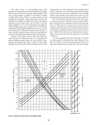
![The subgrade should be uniform, firm, and free from all
sod, grass, humus, and other rich organic matter, as these
materials do not compact. See Chapter 2 for a discussion
of soil properties as they relate to the proper type of sub-
grade and preparation for concrete floors on ground.
For floors with heavy loads—post loads or direct stor-
age on floors—special considerations regarding soil con-
solidation, densification, and/or subsidence are mandato-
ry during design and construction.
Concrete should be placed on a level, uniform surface.
Placement will either be directly on the subgrade or on the
subbase. The subgrade is the natural in-place soil; the sub-
base is generally a compactible fill material that brings the
surface to the proper grade. The subgrade/subbase must
be brought to within required tolerances at the specified
grade. A reasonably accurate, level subgrade will ensure
that the correct thickness of concrete (and subbase if need-
ed) is placed. If the subgrade or subbase surface is uneven,
concrete will be wasted, and the potential for random
cracking will be increased.
Using laser alignment tools permits measurements of
the graded surface to be taken quickly. A scratch template
can be used as a check to reveal high and low spots. For
even faster grading with a high level of accuracy, laser-
guided grading boxes can be used (see Fig. 7-1). This
equipment is capable of fine grading the base to a tolerance
of ± 6 mm (1/4 in.), which can save substantial amounts of
concrete on large slab areas and also improves the surface
flatness and levelness of the floor (Basham 1998). After the
subgrade/subbase has been leveled, it should be compact-
ed. The subgrade/subbase should be moist but not satu-
rated when concrete placement begins (Fig. 7-2).
Section 4.4.1 of ACI 117-90, Standard Specifications for
Tolerances for Concrete Construction and Materials, gives
acceptable thickness tolerances for cast-in-place concrete
slabs. ASTM C 174, Standard Test Method for Measuring
Thickness of Elements Using Drilled Concrete Cores.
For slabs with cross-sections up to 300 mm (12 in.)
thick, the limits are:
+9.5 mm (+3/8 in.) and -6 mm (-1/4 in.)
For slabs thicker than 300 mm (12 in.), but not more
than 900 mm (3 ft) thick, the limits are:
+13 mm (+1/2 in.) and -9.5 mm (-3/8 in.)
The thickness tolerance statement shown above
applies to structural slabs—whether they are on grade or
suspended. From floor load-carrying capability considera-
tions, exceeding the design thickness is not detrimental.
Constructing slabs thinner than shown on the plans, how-
ever, can have a significant impact. The stated -6 mm (-1/4
in.) tolerance can raise flexural stresses by about 10% for
125-mm (5-in.) thick slabs. For thicker slabs, the percent
increase in flexural stress is not as great. In theory, it would
be possible to reduce the tolerance to 3 mm (1/8 in.) for
thinner floors (125 mm to 150 mm [5 in. to 6 in.]) with sig-
nificant loads, but it would be difficult to construct a sub-
grade to such a tight tolerance. Within reason, increased
floor thickness from dimensions shown in contract docu-
ments is acceptable. One caution is that sudden thickness
increases from ruts or holes in the subgrade/subbase
should be avoided, as sudden differences in (concrete)
thickness can lead to localized stresses and cracking.
Where floor elements are thickened, the transition slope
should be shallow (no more than 1 vertical: 10 horizontal).
Concrete Floors on Ground
66
Fig. 7-1. A laser-guided grading box can quickly and accur-
ately level the subgrade. (69660)
Fig. 7-2. Subgrade and/or subbase should be moist when
concrete is placed. (69618)
Book Contents
Publication List](https://image.slidesharecdn.com/eb075concretefloors-210419145726/85/Eb075-concrete-floors-76-320.jpg)
![or presence of an admixture in the concrete and the atmos-
pheric condition at the surface.
Power troweling should be done in a systematic pat-
tern. Two or more passes frequently are required to
increase the compaction of fines at the surface and give
greater resistance to wear. Time must be allowed between
each troweling for the concrete to stiffen and the water
sheen to disappear. The tilt of the trowel blades should be
increased with each pass to exert additional pressure as the
concrete hardens. Each successive troweling should be
made in a direction at right angles to the previous pass.
Jointing
Proper jointing can eliminate unsightly random cracks.
Aspects of jointing that lead to a good job are choosing the
correct type of joint for each location, establishing a good
joint pattern and layout, and installing the joint at the cor-
rect time. Timing of the jointing operations depends on the
tool used to make the joint. (Formed joints have to be made
before troweling.)
Contraction joints can be made with a hand groover, a
preformed insert, or a power saw; however, sawed joints
are the only acceptable type for joints in floors subject to
forklift traffic.
The joint groove, plastic insert, or sawcut should ex-
tend into the slab one-fourth of the slab thickness. Some-
times, a joint depth of one-third the slab thickness is speci-
fied. Some research indicates that a cut shallower than one-
forth may be adequate if made at the proper time. What-
ever the depth of groove, insert, or sawcut specified, it
must be adequate to raise the tensile stress in the reduced
slab section below the joint and thus induce a crack to form
beneath the joint, where it will be inconspicuous.
There are few instances in industrial and commercial
floor work when a hand groover is used to make joints;
however, the groover’s bit must be thin and deep enough
to cut the slab one-fourth of the depth. If joints are created
with hand tools, the control joints should be cut into the
surface while the edging is being done or immediately
after edging.
On large floors it is more convenient to cut joints with
a power saw fitted with an abrasive or diamond blade (Fig.
7-16). Sawing should begin as soon as the surface is firm
enough so that it will not be torn or damaged by the blade,
usually within 4 to 12 hours after the concrete hardens.
However, sawing should be complete prior to the onset of
stresses from curling and contraction. A good rule of
thumb is to complete sawcutting before the new concrete
floor surface cools. Cooling normally occurs the same day
as the concrete placement (depending on the time of day
that placement began).
Contraction or curling stresses can be increased unex-
pectedly. Sudden rain-showers falling on exposed fresh
concrete surfaces will rapidly cool them. This has the
potential to cause restraint stresses and, consequently, ran-
dom cracking. Protecting the fresh surface from drastic
changes in moisture and/or temperature helps prevent
unwanted stresses. The HIPERPAV™ computer program
addresses strength, stress development, and other condi-
tions related to cracking of concrete pavements. It is a help-
ful design and troubleshooting tool. By predicting the
effect of various environmental factors, potentially harm-
ful (crack-inducing) situations can be avoided. During con-
struction, it can be used to identify protective measures for
dealing with unanticipated weather events.
It is important to prevent damage to joint edges. Small,
hard wheels can damage the edges of improperly con-
structed joints. The joints should be filled with a semi-rigid
filler flush with the floor surface. If a joint is formed by an
insert, the insert should be removed by sawing over the
joint alignment and sealing with a semi-rigid filler. Sawing
over the strip to remove it creates the filler reservoir. This
is the only acceptable way to use plastic strips for forming
joints in traffic areas.
Sawcutting the floor to install control joints has tradi-
tionally been done by wet sawing with diamond impreg-
nated blades. Special blades are available for sawing hard
and soft aggregates. Dry sawing with carborundum blades
is done to a limited extent. Dry sawing produces dust, and
the sawcut depth must be frequently monitored because of
potentially rapid blade wear. A more recent innovation is
to cut joints with a relatively small-diameter diamond-
impregnated blade. The blade velocity (revolutions per
minute [rpm]) is much higher than that of the traditional
wet sawcut equipment. Cutting with the high-rpm blade is
done considerably earlier than with traditional methods.
Depth of cut is restricted to 75 mm (3 in.). Two plates (one
on either side of the blade) that rest on top of the concrete
surface and confine the concrete mitigate aggregate ravel-
ing. The equipment is light enough to use on the surface
soon after troweling. If the slab is thicker than about 125
mm (5 in.), it is generally recommended to resaw the crack
to the proper depth at a later time before filling with joint
Chapter 7
75
Fig. 7-16. Control joints can be made by a power saw. These
joints induce straight-line cracking at predetermined
locations. (69657)
Book Contents
Publication List](https://image.slidesharecdn.com/eb075concretefloors-210419145726/85/Eb075-concrete-floors-85-320.jpg)
![FLOOR SURFACE TOLERANCES
For a long time, floor surface tolerances were measured by
laying a straightedge across the floor surface. The quality
of the surface was based on the difference in elevation
between the highest and lowest spots over a 3-m (10-ft)
length. If the difference was small, the floor was fairly flat
in that location; if large, it meant the surface was not as flat.
The straightedge would be moved from one location to
another to measure floor surface flatness.
In the last decade, other methods for measuring floor
surface tolerance were developed because modern vehicles
required flatter surfaces for optimum operation, and more
equitable standards were needed. Of the best known
newer methods, one system is called the F-number system
and the other is known as the surface waviness index
(Wambold and Antle 1996). These methods offer a signifi-
cant advantage over the straightedge method because data
points are collected and saved. If adjustment is necessary
to bring the surface to the required flatness (typically by
grinding), the data make it possible to locate specific areas
on the floor.
These newer methods look at surface differences over
both short lengths and long lengths (chords) and analyze
results using statistics. Elevation differences over short
lengths tell if the surface is bumpy, wavy, or flat, and over
long lengths tell if the surface is sloped, level, or curved.
The measurements not only identify these characteristics,
but make it possible to quantify the surface, that is, tell how
flat or how level it is. ACI recommends that the floor sur-
face tolerance be measured preferably within 24 hours
after placement, but not later than 72 hours after installa-
tion. The Canadian Standards Association suggests taking
the measurements at 72 hours plus-or-minus 12 hours after
completion of the floor finishing.
For the classic method, the 3-m (10-ft) straightedge is
placed in any orientation on the floor surface. With the
straightedge resting on floor surface highpoints, the depth
of a depression in the floor surface is measured. There are
four floor classes to describe the slab surface flatness based
on the depth of depression. For Class AA, the depression is
limited to 3.2 mm (1/8 in.) or smaller; for Class AX, the
limit is 4.8 mm (3/16 in.); for Class BX, the limit is 7.9 mm
(5/16 in.); and for Class CX, it is 12.7 mm (1/2 in.). As ACI
302 points out, there is no accepted standard test procedure
for taking measurements or establishing compliance, so
this method of specifying floor surfaces could lead to con-
flict and litigation.
For the F-number system, also called the “Face Floor
Profile Numbers,” two numbers—a flatness number (FF)
and a levelness number (FL) are used to describe the floor
surface. With this system, floor characteristics are meas-
ured in terms of either metric or inch-pound units, two val-
ues for the floor surface are calculated, and results are
reported as dimensionless ratings.
The FF-number provides criteria for short-wave wavi-
ness of the floor surface. Measurements are made at 300-
mm (1-foot) spacings along straight traverse lines that
extend from joint to joint, but do not cross joints. The flat-
ness number quantitatively describes the bumpiness of the
floor. The FL-number provides limits to surface elevation
variance from design grade. Measurements are made as for
the flatness numbers. The same data used for the flatness
numbers are used to generate the levelness numbers,
which describe how level or slanted the surface is from one
side to another. Notation is always flatness followed by
levelness, with a slash separating the two numbers (FF/FL).
The FF/FL-numbers determine the minimum surface
tolerance acceptable for a floor. Measurements to obtain
the input data for calculating the FF- and FL-number can be
made with an optical level, laser level, leveled straight-
edge, profilograph, dipstick, or digital readout profiler.
Measurements and FF- and FL-number calculations are
made in accordance with ASTM E 1155, Standard Method for
Determining Floor Flatness and Levelness Using the F-Number
System. Though developed in inch-pound units, a com-
plete metric companion to this method has been developed
and is designated ASTM E 1155 M. Floor levelness criteria
should not be applied to floor surfaces purposely sloped,
as, for example, for surface drainage.
The other modern method for assessing a floor surface
is the surface waviness index. The waviness index is
assessed using the standard method described in ASTM E
1486 M, Standard Test Method for Determining Floor
Tolerances Using Waviness, Wheel Path, and Levelness Criteria
[Metric]. (There is a companion inch-pound version desig-
nated ASTM E 1486. Solely for purposes of this discussion,
metric and inch-pound units appear together. There are
two separate standards.) Like the F-number system, it
measures differences in elevation over chords of specific
lengths: usually 0.6 m, 1.2 m, 1.8 m, 2.4 m, and 3.0 m (2 ft,
4 ft, 6 ft, 8 ft, and 10 ft). Readings are taken along a line to
yield a line waviness index (LWI); then these LWIs are
combined into a single value, which is known as the sur-
face waviness index, or SWI. This single number describes
the degree of planeness of the entire floor surface. This is
slightly different from the F-number system, which
describes the planeness of the floor with 2 numbers, one
for flatness and one for levelness (FF/FL). In either system,
results are repeatable, but the two systems are separate and
distinct. While there is no generally recognized correlation
between F-numbers and surface waviness, Table 7-1 pro-
vides a comparison of the various flatness measure-
ments—straightedge tolerance, F-numbers, and SWI.
Note, however, that only one system should be chosen
to describe the surface characteristics of a floor. Table 7-1
compares all three systems. Supporters of the waviness
system, which is often based on chords 0.6 m to 3.0 m (2 ft
to 10 ft), claim it is well suited to floors designed for ran-
dom forklift traffic, because it provides good rideability at
typical speeds. The ACI Committee on tolerances is con-
sidering the suggested standard tolerances. Vinyl tile cov-
ered floors should have an SWI2-10 of about 3 mm (0.12 in.)
Concrete Floors on Ground
78
Book Contents
Publication List](https://image.slidesharecdn.com/eb075concretefloors-210419145726/85/Eb075-concrete-floors-88-320.jpg)

![Adding silica fume or other pozzolans or slag to the
mix can enhance strength and increase abrasion resistance.
High-strength mixes can be susceptible to rapid surface
drying and plastic-shrinkage cracking. Methods for avert-
ing rapid surface evaporation are given on pages 23, 24, 81,
and 82. Good curing is essential not only to produce a hard
top surface but also to avert warping stresses that could
cause debonding before bond strength has developed.
Monolithic Toppings
Monolithic toppings intimately bond to the slab beneath
them, so they can be very thin—13 mm to 25 mm (1/2 in.
to 1 in.). The base slab should be placed and compacted,
then brought to the correct elevation with the topping con-
crete, which is vibrated while the base is still plastic. In this
way the topping becomes part of the structural thickness of
the slab. Construction procedures, panel sizes, joints, and
jointing arrangements are the same as those specified for
the slab itself.
Terrazzo
Portland cement terrazzo is a decorative concrete flooring
material that is typically ground and polished to reveal col-
ored aggregate in a white or colored cement matrix. Its
hard surface is long wearing, which makes it suitable for
heavy duty, high traffic areas where good looks are
desired. Some of the common applications are heavily
used public buildings, such as airport and train terminals,
hospitals, schools, and supermarkets.
The terrazzo surface itself typically is 13 mm (1/2 in.)
thick bonded or monolithically installed over slabs.
Terrazzo surfaces are separated into panels by metal
divider strips that help control unwanted cracking and may
also provide decorative patterns, especially when various
colors are used on adjacent panel sections. The dividers also
serve as leveling guides when placing the terrazzo.
Aggregates most frequently used in conventional
ground and polished terrazzo include granite, marble, and
onyx chips. The chips range in size from 1.6 mm (1/16 in.)
up to 29 mm (1-1/8 in.), but chips can be even wider in
breadth for a different appearance. Two parts of aggregate
are mixed with one part cement matrix, the material is
placed, and additional chips are sprinkled over the top-
ping and troweled into it to achieve the proper consistency
and appearance.
After polishing the floor, a coating of clear epoxy seal-
er can be applied for chemical protection. The National
Terrazzo and Mosaic Association provides information
about specifying and installing these systems.
Separate Bonded Toppings
Separate bonded toppings 19 mm to 25 mm (3/4 in. to
1 in.) thick are applied after the base structural slab has
hardened. A fully bonded topping is considered a part of
the structural thickness of the floor because the base slab
and the topping act together as a monolithic slab. Being
thin, these toppings have little load-carrying capacity of
their own and their satisfactory performance depends
upon their being fully bonded to the base slab.
In preparation for the topping, the slab must be
mechanically roughened so that the coarse aggregate is
exposed and the surface blown clean of dust and debris.
Preparation can be done by rotomilling followed by sand-
blasting or by heavy media shotblasting. For base slabs
with a thick mortar layer near the surface, however, the
scarification need not expose the base slab coarse aggre-
gate. If the base slab concrete is hot and dry, it should be
wetted prior to receiving the bonded topping. After wet-
ting, the surface should be damp (no free water).
Immediately before the topping concrete is placed, a
bonding grout should be brushed into the surface. One
instance when bonding grout may not be needed—which
should be demonstrated by testing—is for a fluid topping
that contains a high cement content. Grout typically con-
sists of 1:1:1/2 cement-sand-water or neat cement (water
plus cement) mixed to a creamy consistency. The slurry is
applied in a thin coat (3-mm [1/8-in.]) and covered with a
topping before the slurry dries out.
Bond Testing
Good bond between topping and base slab is essential for
successful floor performance and high wear resistance. The
quality of the bonded installation can be determined by
bond pulloff tests using the apparatus shown in Fig. 8-6. To
perform the test, a core is drilled through the topping and
bond grout layer into the base concrete. A threaded steel
plug is epoxy-bonded to the topping surface, and a rod
instrumented with a strain gauge is fixed to the threaded
portion of the plug (see Fig. 8-7). Tensile force is applied to
the rod by means of a hydraulic jack. Bond-strength data are
determined from strains in the steel rod at tensile failure.
Examination of the failure surface will demonstrate
where tensile failure occurred, which is one of the five fol-
lowing locations:
• within the topping
• within the bond grout layer
• at the interface between the grout and the topping
• at the interface between the grout and the base slab
• within the base slab concrete
A test method described in ASTM C 1404 provides a
means to measure the adhesive characteristics of materials
used to bond freshly mixed mortar to hardened concrete.
Mode of failure. Because the topping is a high-strength
concrete with a low water-cement ratio, its tensile strength
is in most instances greater than the base slab concrete.
Bonding grouts are also produced with low water-cement
ratios, and may also have greater tensile strength than the
Concrete Floors on Ground
88
Book Contents
Publication List](https://image.slidesharecdn.com/eb075concretefloors-210419145726/85/Eb075-concrete-floors-98-320.jpg)
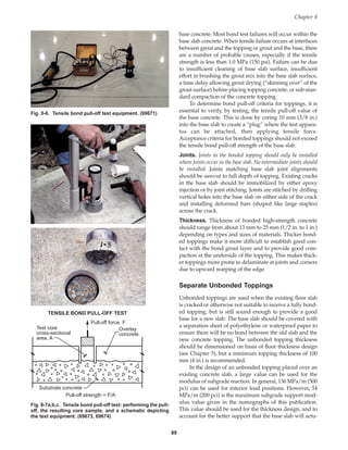
![ally provide, the resulting slab thickness determined from
these figures can be reduced by about 5%. However, it
should be recognized that an unbonded topping slab is
prone to severe upward edge and corner warping if it is
placed over a polyethylene bond breaking slip-sheet over a
very hard base. Thus, this type of construction should be
limited to floors that carry foot traffic and, at best, very
light carts.
Because there is a bondbreaker between the old and
new slabs, joints in the new topping can be laid out in pan-
els to the most suitable size and shape, taking into account
the thickness of the topping and the amount of reinforce-
ment provided (if any). Isolation joints in the base slab,
however, should be extended up through the topping.
FLOOR HARDENERS
Floor hardeners can upgrade wear resistance, reduce dust-
ing, and improve chemical resistance of a floor surface.
These products are normally based on sodium silicate or a
type of fluosilicate. It is important to note that none of
these products will convert a poor-quality floor into a
good-quality floor.
Sodium Silicate (Water Glass)
The cement hydration reaction that takes place during cur-
ing produces hydrated lime [Ca(OH)2] within the concrete
that is converted to calcium carbonate after prolonged
exposure to air. When a solution of sodium metasilicate
(Na2SiO3), commonly known as water glass, is allowed to
soak into the surface, the silicate reacts with calcium com-
pounds to form a hard, glassy substance within the pores
of the concrete. This new substance fills the pores and, after
drying, gives the concrete a denser, harder surface. The
degree of improvement is dependent upon the depth of
penetration by the silicate solution. Therefore, the solution
is diluted significantly to allow adequate penetration.
The treatment consists of two or more coats applied on
successive days. On new concrete, a period of air-drying
after completion of moist-curing gives a reasonably dry
surface to gain maximum penetration. The floor should be
at least 28 days old. The first coat should be a solution of 4
parts by volume of water to 1 part of silicate. The second
coat should be the same solution applied after the first one
has dried. The third coat should be a 3-to-1 solution
applied after the second coat has dried. The treatment is
completed as soon as the concrete surface gains a glassy,
reflective finish. Water-glass treatment will minimize dust-
ing, improve hardness, and increase resistance to chemical
attack, such as from organic acids.
Fluosilicates
Zinc and magnesium fluosilicate sealers are applied in the
same manner as water glass. Each of the compounds can
be used separately or in combination, but a mixture of 20%
zinc and 80% magnesium gives excellent results. For the
first application, 3 parts by weight of fluosilicate com-
pound should be dissolved in 25 parts by weight of water.
(This is equivalent to 120 g of fluosilicate compound per
liter [L] of water, or 1 lb per gallon.) For subsequent coat-
ings, the solution should be 6 parts by weight to each 25
parts of water. (This is the same as 240 g of fluosilicate com-
pound per L of water, or 2 lb per gallon.) To remove
encrusted salts, the floor should be mopped with clear
water shortly after the preceding application has dried.
Safety precautions must be observed when applying these
compounds, owing to their toxicity. Fluoridation of con-
crete surfaces increases the chemical resistance and hard-
ness of the surface.
FLOOR COATINGS
Acids, sugars, and some oils are common chemicals that
can attack concrete floors. Spills should always be cleaned
up quickly. Coatings are applied to floors to improve
chemical resistance, as the concrete by itself resists chemi-
cal attack poorly. Coatings also facilitate housekeeping.
The choice of material or coating system should be
based on how effectively it resists the anticipated exposure
(PCA 2001). When used appropriately, these products offer
good abrasion and chemical resistance and can also be pig-
mented for attractive appearance (PCA 1992). Synthetic
floor coatings include epoxies, polymers, polyurethanes,
chlorinated rubbers, and phenolics. Many of these are pro-
prietary products and are commercially available.
Common to floor coatings is the need for adequate
concrete surface preparation prior to coating application.
The manufacturer’s directions for concrete surface prepa-
ration and application of coatings must be followed close-
ly. New or old, the floor must be treated by shotblasting,
sandblasting, or acid etching to remove surface laitance
and surface contaminants that could prevent bond
between the concrete surface and the coating. Acid etching
is used only when other methods are not practical.
In general, the coating installation consists of a primer
and the coating. The coatings can be applied by roller,
brush, spray, or squeegee. Coating thickness should be as
recommended by the manufacturer but must at least
exceed surface texture or roughness resulting from surface
preparation. Broadcasting silica sand over the wet coating
provides traction on the floor surface, especially useful for
wet exposures. It should be recognized that coatings, like
many floor coverings, are generally impermeable to liquids
and moisture vapor. Successful long-term performance
depends, in part, on absence of moisture vapor pressures
that lead to debonding of the coating. See Chapter 3 for fur-
ther information on moisture control and vapor retarders.
Concrete Floors on Ground
90
Book Contents
Publication List](https://image.slidesharecdn.com/eb075concretefloors-210419145726/85/Eb075-concrete-floors-100-320.jpg)
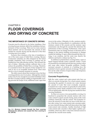
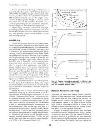
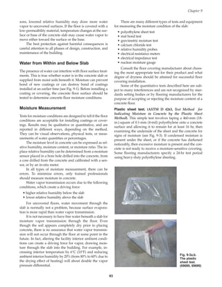
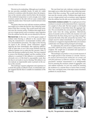
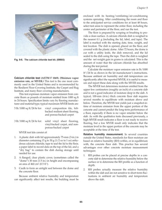
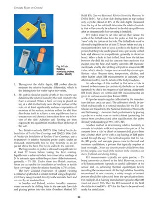
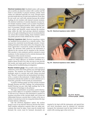
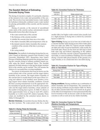
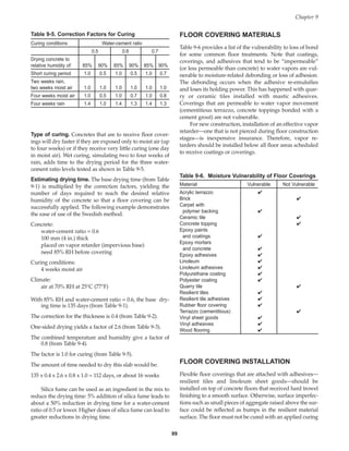
![compound unless tests have shown that the curing com-
pound is compatible with the surface adhesive. The glue is
applied to the clean concrete surface with a notched trowel,
and the covering is pressed into place. Traffic should not be
allowed on the surface until the adhesive has set.
Quarry tile, terrazzo tile, and concrete toppings are
installed over a concrete surface prepared by shotblasting
or sandblasting. If bonded topping installation is sched-
uled, the surface preparation should include rotomilling
followed by sandblasting. Even newly placed concrete
requires shotblasting or sandblasting.
The bond grout for quarry tile can be either a propri-
etary thinset mixture or a cement mixture. The thinset
mixes generally have a latex additive in the mix (usually
contained in the liquid portion of the two-component sys-
tem). The thinset must not be allowed to dry (skin over)
before tiles are pressed into place. Neat cement grouts
(cement plus water mixed to a thick, creamy consistency)
or sand-cement grouts are also used. The thinset or grout is
placed on the prepared, cleaned, and dustfree concrete sur-
face with a notched trowel. Tile should make intimate con-
tact with the grout so that its support is uniform, thus
averting tile cracking under traffic.
Cast-in-place terrazzo should be installed in accor-
dance with the Mosaic Terrazzo Institute methods (NTMA
1999). Base slab surface preparation requirements are as
discussed above for quarry tile installation.
Contraction joints and isolation joints in quarry tile,
ceramic tiles, or terrazzo tile coverings should match those
in the floor base slab. The joints should be full depth and
where exposed to traffic—including foot traffic—they
should be sealed with a semi-rigid epoxy flush with the tile
surface. Spaces between tiles not aligned over contraction
joints should be filled to full depth with a cementitious
joint mortar flush with the surface of adjacent tiles.
Construction joints in base slabs should be treated as con-
traction joints in the covering. Isolation joints should be
filled with a flexible sealant.
COATING FAILURES
When moisture is present in or beneath a concrete slab,
many types of coatings will fail unless they can develop a
good bond soon after application. Nonbreathable coatings
like epoxy, polyester, polyurethane, vinyl ester, and
methacrylate can trap moisture or vapor rising through the
slab, leading to blistering or loss of bond. Coatings can
appear well-bonded even if they have only developed a
bond strength of 0.007 MPa or 0.014 MPa (1 psi or 2 psi). A
well-bonded coating, however, will develop a bond
strength of at least 0.7-MPa (100 psi), and may even exceed
1.4 MPa (200 psi). Neither a hydrostatic head, capillary
action, nor water vapor exerts enough pressure to dislodge
a coating that has a 0.7 MPa (100-psi) bond pull-off
strength. In other words, if a coating can develop good
bond at the time of application, and if the glue is resistant
to moisture (does not dissolve over time), moisture that
rises through the slab will not lead to loss of bond with the
coating. Instead, coatings that suffer moisture-related dam-
age probably never achieved a good bond to the concrete
(Gaul 1996).
Moisture can cause coating failures in two ways: by
preventing proper cure, or by allowing cure but preventing
good bond. For some coatings, the chemical cure is inter-
rupted or severely retarded by the presence of moisture.
This results in a soft coating or one that is sticky on its
underside. There may be a noticeable odor from one of the
coating components. Visually, small blisters (diameter less
than 6 mm [1/4 in.]), closely spaced, will be noticeable.
If the coating cures properly and completely in the
presence of water, there is still the possibility that it will not
achieve good bond under certain moisture conditions. The
experience of the coatings industry has shown that a mois-
ture vapor transmission rate of more than 2.5 kg per 100 m2
per 24 hr (5 lb per 1000 ft2 per 24 hr) (as measured by
ASTM F 1869) can lead to failure. If this type of failure
occurs, the coating has a hard underside that can be easily
peeled from the surface using a blade (putty knife).
Whereas coatings whose cure is prevented by moisture
exhibit small blisters, poorly-bonded coatings exhibit larger
diameter blisters. If osmotic pressure develops, these blis-
ters may contain water under pressure, which will squirt
out when the blister is punctured.
Before a coating is applied, the moisture condition of
the floor must be known. See “Moisture Measurement”
earlier in this chapter for a description of various methods
available for checking moisture in concrete.
To avoid moisture-related failures of floor coverings
due to poor bond, several approaches are suggested. A
vapor retarder located under the slab is the first line of
defense. This prevents excess water from reaching the
underside of the slab.
Breathable coatings. When possible, a coating that
breathes should be used. The trouble with these coatings is
that they are not generally very resistant to chemicals, do
not protect the concrete from water penetration, and are
more difficult to clean.
Proper ambient conditions. Turning off heating or air
conditioning systems reduces the moisture gradient
between the underside and top of a slab. Concrete should
be protected from the sun when coatings are applied. If
concrete is warmed by the sun, water vapor pressure in the
capillaries increases, and a vapor pressure gradient is
established. This tends to push coatings off the surface.
Installing the coatings in the shade and when the concrete
temperature is dropping helps to pull the coating into the
concrete.
Primers. Afast-setting primer will bond quickly to the slab
and should be considered. This material can develop bond
quickly, before moisture collects under the coating or
before vapor pressure builds up to interfere with the bond.
Concrete Floors on Ground
100
Book Contents
Publication List](https://image.slidesharecdn.com/eb075concretefloors-210419145726/85/Eb075-concrete-floors-110-320.jpg)
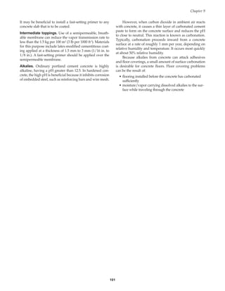

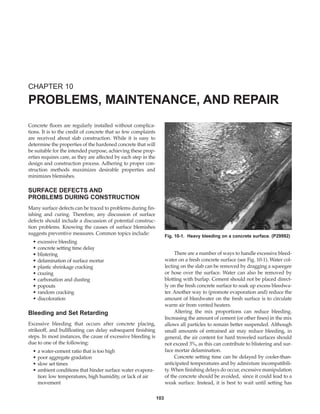
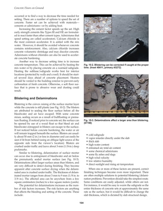
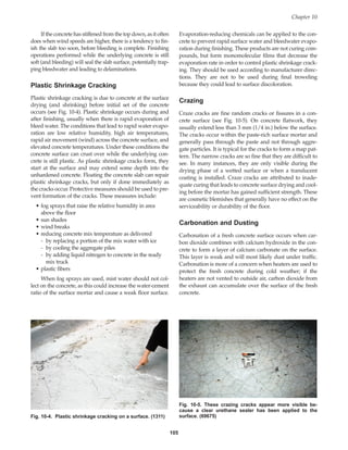
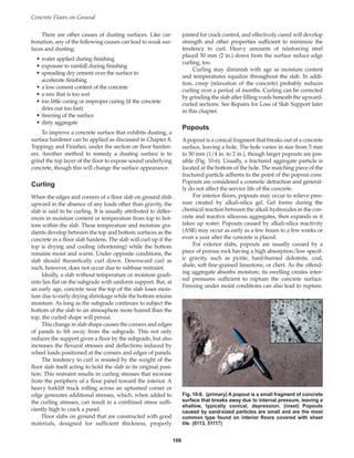
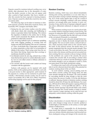
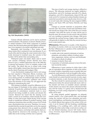
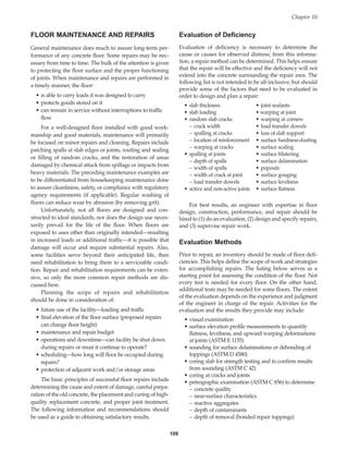

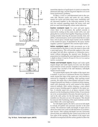
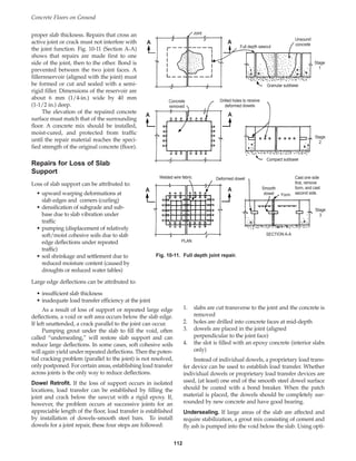
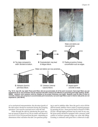
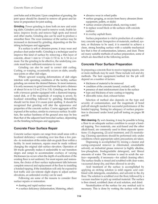
![115
water, sprinkling on a detergent cleaner (highly alkaline,
high-phosphate, non-residue detergent), scrubbing, rinsing
with water, and vacuuming damp-dry. The surface is then
rinsed again with clear water, vacuumed damp-dry, and
allowed to air-dry before applying the new surface finish.
An acid treatment is recommended only for cleaning
floor surfaces that are to receive a new surface finish. Acid
treatment of floors has become less and less common
because the acid cleaners require strict handling and dis-
posal procedures for safety.
Other wet cleaning methods include high-pressure
water-jet blasting and steam cleaning (see Fig. 10-13) (PCA
1995a). Tough cleaning jobs require the use of heat (up to
about 95°C [200°F]) and chemicals. Water blasting can be
done with or without abrasives and at varying water pres-
sures. In addition to water, abrasives may be used to
improve the cutting action. Water blasters can be used to
scarify the concrete surface, removing only 6 mm (1/4 in.).
At the other extreme, water jets can remove concrete
depths up to 300 mm (12 in.). Operating pressures vary
from 0.6 MPa to 69 MPa (100 psi up to 10,000 psi), with 14
MPa to 21 MPa (2000 psi or 3000 psi) being common for
cleaning. Steam cleaning can be done with or without
chemicals. But because it is slow, requires high water tem-
peratures, and does not do as good a job as pressure wash-
ers, steam cleaning slabs is generally not economical.
Dry preparation. Mechanical methods offer an efficient
and economical way to dry clean a concrete surface.
Equipment is available for scabbling, scarifying, grind-
ing, shotblasting, planing, and flame cleaning. Some
machines have a variety of interchangeable cutting and
brushing heads.
Most scabbling and scarifying machines are mecha-
nized versions of a hammer and chisel. Scabbling uses an
air-driven machine that has a varying number of pistons
mounted in a block. Each piston is fitted with a tungsten
carbide bit. Operating much the same as a bushhammer or
chipping hammer (Fig. 10-14), the striking action shatters
away the surface contamination, exposing a clean, sound
concrete with a good mechanical key for bonding.
Scarifying uses a power-driven tool with rotary heads
that can be fitted with a wide variety of scrubbing brushes,
cutting wheels, scouring brushes, and steel scarifying
brushes. Large open areas are suited for scarification by
machine. Scarifying and scabbling tend to roughen the sur-
face more than shotblasting or abrasive blasting.
Shotblasting is done by closed-cycle steel-particle
bombardment to remove any surface contaminants. Shot-
blasting is virtually dust free and is frequently used to pre-
pare floors for installation of coatings.
Planing machines can remove laitance, paint marks,
pitch adhesives, and thermoplastic adhesives, and can cut
back the level of the concrete. Other uses include grooving
the concrete and making nonskid surfaces. The machines
have hardened-steel cutting wheels for hammering off the
surface.
Scabbling, bushhammering, rotomilling, and chipping
cause impacts at the concrete surface (see Fig. 10-15). These
impacts can cause horizontal or near-horizontal cleavage
planes that reduce concrete tensile strength at the surface. To
determine if the tensile strength has been reduced, a bond
pull-off test is made. Where tensile strength is lower due to
the impact scarification process, abrasive blasting or water
blasting is required before installing the bonded topping.
Concrete Overlays
When surface wear has reached a point considered detri-
mental to building operations, action is required to rebuild
Chapter 10
Fig. 10-13. Water blasting or jet blasting is an effective
method of removing concrete without harming the concrete
substrate that remains. (69700)
Fig. 10-14. Weak, defective concrete can be removed with a
chipping hammer or jack hammer. (69677)
Book Contents
Publication List](https://image.slidesharecdn.com/eb075concretefloors-210419145726/85/Eb075-concrete-floors-125-320.jpg)
![Concrete Floors on Ground
116
and restore the original surface. The choice of repair
method depends on cost, volume of the repair area, accept-
able downtime, required strength, required chemical and
abrasion resistance, and ambient conditions while repair is
underway.
Abonded topping (also called thin-bonded resurfacing)
can be installed using normal or high-strength portland
cement concrete mixes or epoxy concrete formulations. With
concrete overlays, bonding grouts may be used, but are not
always necessary. Concrete overlay mixes that have a high
paste content or that are fluid usually do not require a bond-
ing grout. A test patch should be placed to verify the ade-
quacy of bond. When bonding grouts are used, they can
either be cementitious (neat cement) or epoxy primers
and/or epoxy grouts. Many epoxy materials are not resist-
ant to moisture, so they should not be used where moisture
barriers were not installed below the concrete slab (as dis-
cussed in Chapter 3 ), nor anywhere else there is a potential
for water vapor pressure in the slab. Some epoxies can be
used in moist conditions without concern.
When relatively small areas on the concrete surface
require repair, bonded patching is used. The basic princi-
ples are the same as for toppings. Both patching and thin-
bonded resurfacing are discussed below.
BONDED PATCHING
Surface preparation is the key to producing a well-bonded,
shallow concrete patch. Usually, if the patch fails to bond
tightly, it is because laitance, dust, or other contaminants
were not properly removed from the floor surface.
All weak and defective concrete must be removed,
preferably by saw-cutting 20 mm (3/4 in.) deep around the
perimeter of the patch, followed by removal of defective
concrete with a chipping hammer, a bushhammer, or a
scabbler. A chipping hammer should not be heavier than
the nominal 7-kg (15-lb) class. Hand tools such as hammers
and chisels should be used to remove all final particles of
unsound concrete. If needed, gritblasting or water-jet blast-
ing should follow. This step can clean the exposed rein-
forcement of attached mortar and visible rust. It also cleans
all concrete surfaces against which new patch material will
be placed. Prior to placing new concrete, the surface
should be blown clean by airblast, free of compressor oils,
and then flushed with water. Puddles of free water must be
removed before placing the patch.
If using a bonding grout (optional), it should be placed
immediately prior to placing the new concrete. The
cleaned surface should be brushed with a thin (3-mm [1/8-
in.]) coat of freshly mixed grout consisting of sand, cement,
and water (see Fig. 10-16). This bonding grout should have
one part fine sand (2.36 mm [No. 8] maximum size) and
one part portland cement mixed with one-half part water
to give a creamy consistency. Alternately, the bonding
grout could consist of a neat cement mixture (no sand).
Whichever grout is chosen, it should be applied at a rate
that will keep it from drying or skinning over before it is
covered with new concrete.
Mix proportions for patching concrete. When normal or
high-early-strength portland cement is used for the repair,
the mix proportions by volume for concrete and mortar
should be as follows:
Mortar (for patches less than 25 mm [1 in.] thick):
1 part portland cement
2-1/2 to 3 parts sand
Concrete (for deeper patches):
1 part portland cement
2-1/2 parts sand
2-1/2 parts coarse aggregate
Fig. 10-15. Shotblasting removes concrete by impelling
steel shot towards the surface. (52255)
Fig. 10-16. A bonding grout is scrubbed into the prepared
concrete surface with a stiff broom. (69678)
Book Contents
Publication List](https://image.slidesharecdn.com/eb075concretefloors-210419145726/85/Eb075-concrete-floors-126-320.jpg)
![uously wet for 24 hours, and then covered with polyethyl-
ene film or waterproof paper for an additional 48 hours.
Ambient conditions (hot or cold, dry or humid, calm or
windy) dictate the choice of a satisfactory curing method.
Thin Bonded Topping
A fully bonded concrete topping is usually at least 20 mm
(3/4 in.) thick; an unbonded topping is usually a mini-
mum of 100 mm (4 in.) thick. The thickness of an overlay
must be considered because it raises the level of the floor.
The best surface preparation for a bonded overlay is
obtained with one of the dry-cleaning methods described
previously. If contamination is present after dry cleaning,
then wet-cleaning methods should be used to further pre-
pare the surface. An effective check for contamination is to
sprinkle water on the concrete: if the water forms little
globules, contaminants are present that will interfere with
bond. If the water is immediately absorbed, it can be
assumed that the concrete is clean. For surfaces contami-
nated to significant depth by oils—as for example machine
building and automotive production plants—petrographic
examination will provide guidance on the depth of scarifi-
cation needed to reach sound concrete that will provide
good bond pull-off strength.
Mix preparation for bonded overlays. Volume propor-
tions are suitable for small patches, but for large resurfac-
ing jobs, weight batching should be used to eliminate vari-
ations in quality. The mix design varies, depending upon
the thickness of concrete to be placed. The water-cement
ratio can range from 0.33 to 0.45. Aggregates can be select-
ed for their hardwearing and abrasion-resisting qualities.
Low-slump concrete generally works well (50 mm to 75
mm [2 in. to 3 in.]). Adjustments in consistency depend on
thickness of topping, temperature, and equipment avail-
able to do the work. A water-reducing admixture can
improve workability of low-slump concrete, and a super-
plasticizer can produce high-strength concrete at flowable
consistencies.
Formwork. The same principles that apply to edge forms
in general apply to topping forms. The method of
installing and anchoring varies greatly depending on the
job conditions. The forms and intermediate screeds must
be set to grade and positively anchored in position to
maintain a true level.
Laying the topping. The topping should be placed in pan-
els with panel edges aligned with base slab joints. The top-
ping must be well compacted to ensure bond, strength,
and durability. On large projects, a self-propelled finishing
machine with vibrating screed supported on guide rails
should be used. On smaller jobs, a manually operated
vibratory screed or tamper can give satisfactory results.
Various methods of finishing floor slabs have already
been discussed. The new surface must be moist cured for
at least 3 days (preferably 7 days). One practical and satis-
117
For concrete patches, the maximum size of coarse
aggregate is limited to roughly one-third the patch depth.
For 20 mm (3/4 in.) thick topping patches, the maximum
size of coarse aggregate should be 10 mm (3/8 in.). For 50
mm (2 in.) thick patches, the maximum size of coarse
aggregate should be 19 mm (3/4 in.).
The materials are proportioned to make a low-slump
mix using a water-cement ratio not to exceed 0.44 by weight.
Concrete subjected to freeze-thaw cycles and deicer chemi-
cals needs an adequate system of air entrainment with about
5% to 7% total air content (9% for mortar). Where rapid
reuse of the patched area is needed, calcium chloride, not to
exceed 2% by weight of cement, can be used to accelerate
hardening and early-strength gain of non-reinforced con-
crete. Topping patches must not be feather edged.
Caution: Calcium chloride should not be used when dissim-
ilar metals or electrical conduit are encased in the concrete.
Placing and finishing the concrete. Some type of surface
vibration is mandatory for compacting surface patches. A
hand-operated vibratory screed or strikeoff is effective, as
is a portable plate vibrator or compactor float. Hand tamp-
ers can be used when power equipment is not available.
New concrete should be placed and struck off slightly
above the final grade and then mechanically vibrated,
screeded, and floated to final grade (see Fig. 10-17). When a
stiff, low-slump mix is used, there may be no water gain on
the surface. Troweling should not be done when there is free
water on the surface and should not be done to the extent
that free water will be brought to the surface. When the sur-
face has become quite hard, it should be given a second and
third troweling to produce a very hard, dense finish.
Curing. Evaporation of water from thin-concrete patches is
rapid, and if not prevented immediately after the concrete
is finished, rapid evaporation may cause surface crazing,
cracking, and curling. Covering the patch with wet burlap
prevents rapid drying. The surface should be kept contin-
Chapter 10
Fig. 10-17. A stiff mix is placed onto a slab area coated with
a still-wet bonding grout. (69679)
Book Contents
Publication List](https://image.slidesharecdn.com/eb075concretefloors-210419145726/85/Eb075-concrete-floors-127-320.jpg)
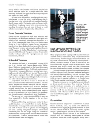
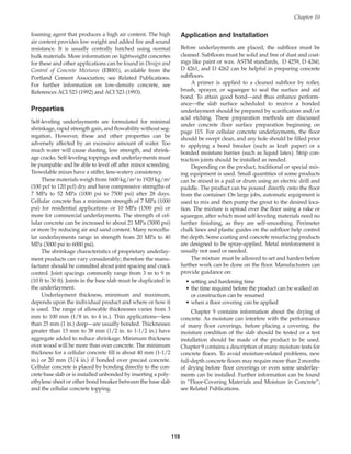

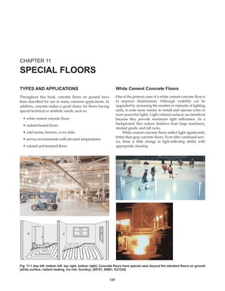
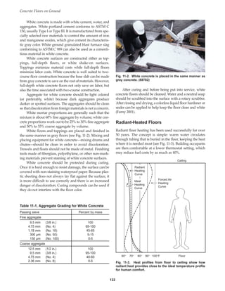
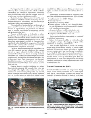
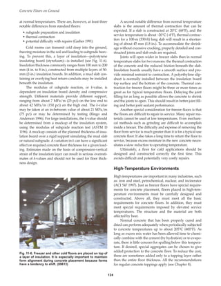
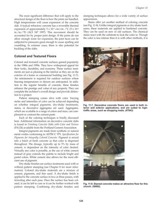
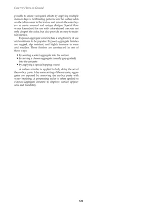
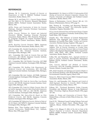
![Concrete Floors on Ground
128
Gilbert, R. I., “Shrinkage Cracking in Fully Restrained
Concrete Members,” ACI Structural Journal, American
Concrete Institute, Farmington Hills, Michigan, March-
April 1992, pages 141–49.
Greening, N. R., and Landgren, R., Surface Discoloration of
Concrete Flatwork, Research Department Bulletin RX203,
Portland Cement Association, Skokie, Illinois, 1966.
Goodyear, Off-The-Road Tires Engineering Data Book,
Goodyear Tire and Rubber Co., Akron, Ohio, 2001, (view at
www.goodyearotr.com/otr/index.html).
Goeb, E. O., “Technical Talk: Do Plastic Fibers Replace Wire
Mesh in a Slab on Grade?” Concrete Products, Primedia
Intertec, Overland Park, Kansas, March 1989, page 11.
Haddadin, M.J., Computer Program for the Analysis and
Design of Foundation Mats and Combined Footings, SR100,
Portland Cement Association, Skokie, Illinois, 1971.
Hanley-Wood, “Effect of High Temperature on Hardened
Concrete,” Concrete Construction, Hanley-Wood, LLC,
Addison, Illinois, November 1971, pages 477–479.
Hanson, J.A., Effects of Curing and Drying Environments on
Splitting Tensile Strength of Concrete, Development Depart-
ment Bulletin DX141, Portland Cement Association,
Skokie, Illinois, 1968.
Hedenblad, G., Drying of Construction Water in
Concrete–Drying Times and Moisture Measurement, T9,
Swedish Council for Building Research, Stockholm, 1997.
[Available from Portland Cement Association as LT229.]
Hedenblad, G., “Drying of Construction Water in
Concrete–The Swedish Experience,” Issues in Moisture
Migration in Concrete, ACBM Technology Transfer Day,
NSF Center for Advanced Cement-Based Materials (at
Northwestern University), Evanston, Illinois, April 1998.
Hetenyi, M., Beams on Elastic Foundations, The University of
Michigan Press, Ann Arbor, Michigan, 1946, 255 pages.
HRB, Road Test One-MD, Highway Research Board, 1952.
HRB, The AASHTO Road Test, Highway Research Board
Special Report No. 61E, 1962.
Kanare, H. M., Understanding Concrete Floors and Moisture
Issues, CD014, Portland Cement Association, Skokie,
Illinois, 2000.
Kelley, E.F., “Applications of the Results of Research to the
Structural Design of Concrete Pavements,” Public Roads,
Vol. 20, No. 5, July 1939, pages 83–104.
Kosmatka, S. H., “Floor-Covering Materials and Moisture
in Concrete,” Concrete Technology Today, PL853, Portland
Cement Association, Skokie, Illinois, September 1985.
Kosmatka, S. H., “Sulfate-Resistant Concrete,” Concrete
Technology Today, PL883, Portland Cement Association,
Skokie, Illinois, October 1988, 3 pages.
Kosmatka, S. H., “Bleeding,” Significance of Tests and
Properties of Concrete and Concrete-Making Materials, STP
169C, American Society for Testing and Materials, West
Conshohocken, Pennsylvania, 1994, pages 88–111. [Also
available from PCA as RP328.]
Kosmatka, S. H., and Panarese, W.C., Design and Control of
Concrete Mixtures, EB001, 13th edition, Portland Cement
Association, Skokie, Illinois, revised 1994, 212 pages.
Kunt, M. M., and McCullogh, B. F., “Evaluation of the
Subbase Drag Formula by Considering Realistic Subbase
Friction Values,” Transportation Research Record 1286,
Transportation Research Board National Research Council
Washington, D.C., 1990, pages 78–83.
Landgren, R., and Hadley, D.W., Surface Popouts Caused by
Alkali-Aggregation Reaction, RD121, Portland Cement
Association, Skokie, Illinois, (to be published) late 2001.
Liu, T. C., “Abrasion Resistance of Concrete,” ACI Journal,
American Concrete Institute, Farmington Hills, Michigan,
September–October 1981.
Lytton, R.L., and Meyer, K.T., “Stiffened Mats on
Expansive Clay,” Journal, Soil Mechanics and Foundations
Division, American Society of Civil Engineers, July 1971.
Marais, L. R., and Perrie, B. D., Concrete Industrial Floors on
the Ground, Portland Cement Institute, Midrand, South
Africa, 1993.
Miller, F.M., Powers, L.J., Taylor, P.C., Investigation of
Discoloration in Concrete Slabs, Serial No. 2228, Portland
Cement Association, Skokie, Illinois, 1999, 22 pages.
Monfore, G. E., A Small Probe-Type Gage for Measuring
Relative Humidity, Research Department Bulletin RX160,
Portland Cement Association, Skokie, Illinois, May 1963.
NAHB, Building Radon Resistant Foundations, #TR104,
National Association of Home Builders National Research
Center, Upper Marlboro, Maryland, 1989.
NAS, Critical for Selection and Design of Residential Slabs-on-
Ground, U.S. National Academy of Sciences Publication
1571, Washington, D.C., 1968.
Nicholson, L. P., “How to Minimize Cracking and Increase
Strength of Slabs on Grade,” Concrete Construction, Hanley-
Wood, LLC, Addison, Illinois, 1981, pages 739–742.
Nowlen, W. J., “Influence of Aggregate Properties on
Effectiveness of Interlock Joints in Concrete Pavements,”
Journal of the PCA Research and Development Laboratories, Vol.
10, No. 2, Portland Cement Association, Skokie, Illinois,
May 1968.
NTMA, Terrazzo Specifications and Design Guide, The
National Terrazzo and Mosaic Association, Inc., Leesburg,
Virginia, 1999, 50 pages (pdf).
Okamoto, P. A., and Nussbaum, Peter J., Concentrated Loads
on Industrial Concrete Floors on Grade, Serial No. 1943,
Portland Cement Association, Skokie, Illinois, July 1984.
Packard, R.G., Computer Program for Airport Pavement
Design, SR029, Portland Cement Association, 1967.
Book Contents
Publication List](https://image.slidesharecdn.com/eb075concretefloors-210419145726/85/Eb075-concrete-floors-138-320.jpg)
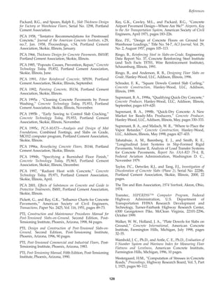
![Wood, S. L., Evaluation of the Long-Term Properties of
Concrete, RD102T, Portland Cement Association, Skokie,
Illinois, 1992.
Wu, C., and Okamoto, P. A., Refinement of the Portland
Cement Association Thickness Design Procedure for Concrete
Highway and Street Pavements, Serial No. 1916, Portland
Cement Association, Skokie, Illinois, 1992
STANDARDS—ASTM AND OTHER
ASTM A 82-97a, Standard Specification for Steel Wire, Plain,
for Concrete Reinforcement
ASTM A 184/A 184M, Standard Specification for Fabricated
Deformed Steel Bar Mats for Concrete Reinforcement
ASTM A 185, Standard Specification for Steel Welded Wire
Fabric, Plain, for Concrete Reinforcement
ASTM A 496, Standard Specification for Steel Wire, Deformed,
for Concrete Reinforcement
ASTM A 497, Standard Specification for Steel Welded Wire
Fabric, Deformed, for Concrete Reinforcement
ASTM A 615/A 615M, Standard Specification for Deformed
and Plain Billet-Steel Bars for Concrete Reinforcement
ASTM A 704/A 704M, Standard Specification for Welded Steel
Plain Bar or Rod Mats for Concrete Reinforcement
ASTM A 706/A 706M, Standard Specification for Low-Alloy
Steel Deformed and Plain Bars for Concrete Reinforcement
ASTM A 767/A 767M, Standard Specification for Zinc-Coated
(Galvanized) Steel Bars for Concrete Reinforcement
ASTM A 820, Specification for Steel Fibers for Fiber-Reinforced
Concrete
ASTM A 884/A 884M, Specification for Epoxy-Coated Steel
Wire and Welded Wire Fabric for Reinforcement
ASTM A 955M, Standard Specification for Deformed and Plain
Stainless Steel Bars For Concrete Reinforcement [Metric]
ASTM A996/A996M-01, Specification for Rail-Steel and Axle-
Steel Deformed Bars for Concrete Reinforcement
ASTM C 33, Specification for Concrete Aggregates
ASTM C 42, Method for Obtaining and Testing Drilled Cores
and Sawed Beams of Concrete
ASTM C 78, Test Method for Flexural Strength of Concrete
(Using Simple Beam with Third-Point Loading)
ASTM C 94, Standard Specification for Ready-Mixed Concrete
ASTM C 150, Standard Specification for Portland Cement
ASTM C 157, Standard Test Method for Length Change of
Hardened Hydraulic-Cement Mortar and Concrete
ASTM C 174, Standard Test Method for Measuring Thickness
of Concrete Elements Using Drilled Concrete Cores
ASTM C 232, Test Methods for Bleeding of Concrete
ASTM C 260, Specification for Air-Entraining Admixtures for
Concrete
ASTM C 295, Practice for Petrographic Examination of
Aggregates for Concrete
ASTM C 330, Specification for Lightweight Aggregates for
Structural Concrete
ASTM C 494 and ASTM C 494M, Specification for Chemical
Admixtures for Concrete
Concrete Floors on Ground
130
Book Contents
Publication List](https://image.slidesharecdn.com/eb075concretefloors-210419145726/85/Eb075-concrete-floors-140-320.jpg)
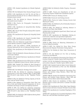
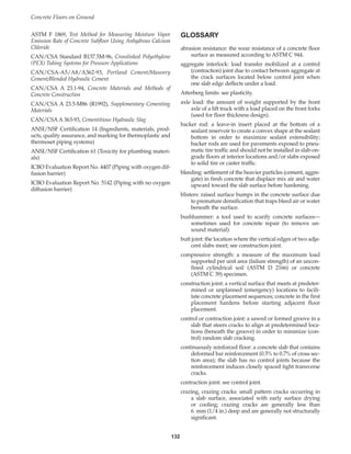
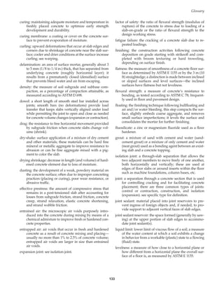
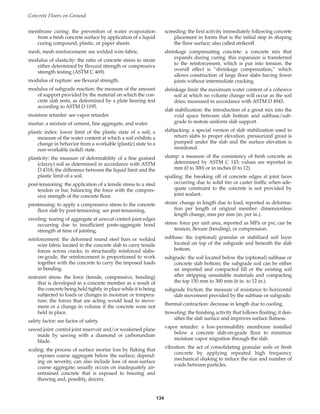
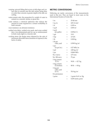
![RELATED PUBLICATIONS
The publications cited in this text as well as other related
publications can be purchased from Portland Cement
Association. The following are particularly useful:
Cement Mason’s Guide, (PA122)
Concrete Slab Surface Causes, Prevention, Repair, (IS177)
Design and Control of Concrete Mixtures, (EB001)
“Discoloration of Concrete—Causes and Remedies,”
Concrete Technology Today (PL861)
Drying of Construction Water in Concrete—Drying Times and
Moisture Measurement (LT229)
Effects of Substances on Concrete and Guide to Protective
Treatments (IS001)
“Floor-Covering Materials and Moisture in Concrete,”
Concrete Technology Today (PL883)
“How to Double the Value of Your Concrete [Floor]
Dollar,” Concrete Technology Today (PL852)
Maintenance of Joints and Cracks in Concrete Pavements
(IS188)
Painting Concrete (EB007)
PCA Soil Primer (EB007)
Removing Stains and Cleaning Concrete Surfaces (IS214)
“Repair with Thin-Bonded Overlay,” Concrete Technology
Today (PL851)
Resurfacing Concrete Floors (IS144)
Slab Thickness Design for Industrial Concrete Floors on Grade
(IS195)
Steel Fiber Reinforced Concrete Properties and Resurfacing
Applications (RD049)
Subgrades and Subbases for Concrete Pavements (IS029)
Surface Treatments for Concrete Floors (IS147)
Transporting and Handling Concrete (IS178)
Understanding Concrete Floors and Moisture Issues (CD014)
White Cement Concrete (EB217)
To order, write, phone, or fax
Customer Service
Portland Cement Association
PO Box 726
Skokie, IL 60076-0726
847.966.6200, ext. 564
800.868.6733 toll free
847.966.9666 fax
Or visit our Web site at www.portcement.org.
Listings of PCA materials are available in the Association’s
various catalogs of publications, computer software, and
audiovisual materials. Free.
An organization of cement companies to improve
and extend the uses of portland cement and concrete
through market development, engineering, research, edu-
cation, and public affairs work.
RELATED WEB SITES
American Concrete Institute
ACI www.aci-int.org
American Concrete Paving Association
ACPA www.pavement.com
American Society for Testing and Materials
ASTM www.astm.org
Canadian Standards Association
CSA www.csa.ca
Construction Specifications Institute
CSI www.csi.org
Decorative Concrete Council
DCC www.decorativeconcretecouncil.org/
Decorative Concrete Network
DCN www.decorative-concrete.net/
National Terrazzo and Mosaic Association
NTMA www.ntma.com
Portland Cement Association
PCA www.portcement.org
Post-Tensioning Institute
PTI www.post-tensioning.org
Concrete Floors on Ground
136
Book Contents
Publication List](https://image.slidesharecdn.com/eb075concretefloors-210419145726/85/Eb075-concrete-floors-146-320.jpg)