SlideShare a Scribd company logo
1 of 39
Download to read offline
Switch Mode Power Supply (15/25/35/50/75/100/150/200/350-W Models)
1
Switch Mode Power Supply (15/25/35/50/75/100/150/200/350-W Models)
S8FS-C
High Reliability at a Reasonable Cost.
Reliable, Basic Power Supplies That
Contribute to Stable Equipment
Operation.
• High Reliability: Enhanced abnormal overvoltage
resistance and lightning surge resistance for stable
operation even with an unstable input voltage.
• Long Life: 105°C electrolytic capacitors are used
to achieve stable quality and long life.
• Wide Input Ranges: 100 to 120 VAC and 200 to 240 VAC
• Global Standards: Conforms to CE (all models), Approved
for cURus (all models) and CCC (15 to 150-W models).
• Easy mounting to DIN Rails with Mounting Brackets (sold
separately).
• 3-year warranty
* Refer to Period and Terms of Warranty on page 36.
Product Lineup
Model Number Structure
Model Number Legend
Note: Not all combinations are possible. Refer to List of Models in Ordering Information on page 2.
Refer to Safety Precautions for All Power Supplies
and Safety Precautions on page 33.
Output
voltage
Power rating
15 W 25 W 35 W 50 W 75 W 100 W 150 W 200 W 350 W
5 V Yes Yes Yes Yes Yes Yes Yes Yes Yes
12 V Yes Yes Yes Yes Yes Yes Yes Yes Yes
15 V Yes Yes Yes Yes Yes Yes Yes --- ---
24 V Yes Yes Yes Yes Yes Yes Yes Yes Yes
36 V --- --- --- --- --- Yes Yes Yes Yes
48 V --- --- --- Yes Yes Yes Yes Yes Yes
S8FS-C
(1) (2) (3)
(1) Power Rating (2) Output Voltage
Code Power rating
015 15 W
025 25 W
035 35 W
050 50 W
075 75 W
100 100 W
150 150 W
200 200 W
350 350 W
Code Output voltage
05 5 V
12 12 V
15 15 V
24 24 V
36 36 V
48 48 V
(3) Terminal Block Direction
Code Terminal Block Direction
Blank
Models with terminal block
facing upward
J
Models with terminal block
facing forward
S8FS-C
2
Ordering Information
List of Models
Note: For details on normal stock models, contact your nearest OMRON representative.
Note: You can use brackets that are sold separately to mount the Power Supplies to DIN Rail. Refer to Mounting Brackets (Order Separately) on
page 26.
*1. The range for compliance with EC Directives and safety standards (UL, EN, etc.) is 100 to 240 VAC (85 to 264 VAC).
*2. The range for compliance with EC Directives and safety standards (UL, EN, etc.) is 100 to 120 VAC (85 to 132 VAC) or 200 to 240 VAC (176
to 264 VAC).
*3. The range for compliance with EC Directives and safety standards (UL, EN, etc.) is 100 to 120 VAC (90 to 132 VAC) or 200 to 240 VAC (180
to 264 VAC).
Power rating Input voltage
Output voltage
(VDC)
Output current Built-in fan
Model with
terminal block
facing upward
Model with
terminal block
facing forward
15 W
100 to 240 VAC
(allowable range:
85 to 264 VAC or
120 to 370 VDC
*1)
5 V 3 A
None
---
S8FS-C01505J
12 V 1.3 A S8FS-C01512J
15 V 1 A S8FS-C01515J
24 V 0.7 A S8FS-C01524J
25 W
5 V 5 A S8FS-C02505 S8FS-C02505J
12 V 2.1 A S8FS-C02512 S8FS-C02512J
15 V 1.7 A S8FS-C02515 S8FS-C02515J
24 V 1.1 A S8FS-C02524 S8FS-C02524J
35 W
5 V 7 A S8FS-C03505 S8FS-C03505J
12 V 3 A S8FS-C03512 S8FS-C03512J
15 V 2.4 A S8FS-C03515 S8FS-C03515J
24 V 1.5 A S8FS-C03524 S8FS-C03524J
50 W
5 V 10 A S8FS-C05005 S8FS-C05005J
12 V 4.2 A S8FS-C05012 S8FS-C05012J
15 V 3.4 A S8FS-C05015 S8FS-C05015J
24 V 2.2 A S8FS-C05024 S8FS-C05024J
48 V 1.1 A S8FS-C05048 S8FS-C05048J
75 W
5 V 14 A S8FS-C07505 S8FS-C07505J
12 V 6.2 A S8FS-C07512 S8FS-C07512J
15 V 5 A S8FS-C07515 S8FS-C07515J
24 V 3.2 A S8FS-C07524 S8FS-C07524J
48 V 1.6 A S8FS-C07548 S8FS-C07548J
100 W
100 to 120 VAC,
200 to 240 VAC
(allowable range:
85 to 132 VAC,
176 to 264 VAC, or
248 to 373 VDC
(Select with the switch.)
*2)
5 V 20 A S8FS-C10005 S8FS-C10005J
12 V 8.5 A S8FS-C10012 S8FS-C10012J
15 V 7 A S8FS-C10015 S8FS-C10015J
24 V 4.5 A S8FS-C10024 S8FS-C10024J
36 V 2.8 A S8FS-C10036 S8FS-C10036J
48 V 2.3 A S8FS-C10048 S8FS-C10048J
150 W
100 to 120 VAC,
200 to 240 VAC
(allowable range:
90 to 132 VAC,
180 to 264 VAC, or
254 to 373 VDC
(Select with the switch.)
*3)
5 V 26 A S8FS-C15005 S8FS-C15005J
12 V 12.5 A S8FS-C15012 S8FS-C15012J
15 V 10 A S8FS-C15015 S8FS-C15015J
24 V 6.5 A S8FS-C15024 S8FS-C15024J
36 V 4.3 A S8FS-C15036 S8FS-C15036J
48 V 3.3 A S8FS-C15048 S8FS-C15048J
200 W
5 V 40 A S8FS-C20005 S8FS-C20005J
12 V 17 A S8FS-C20012 S8FS-C20012J
24 V 8.8 A S8FS-C20024 S8FS-C20024J
36 V 5.9 A S8FS-C20036 S8FS-C20036J
48 V 4.43 A S8FS-C20048 S8FS-C20048J
350 W
5 V 60 A
Yes
S8FS-C35005 S8FS-C35005J
12 V 29 A S8FS-C35012 S8FS-C35012J
24 V 14.6 A S8FS-C35024 S8FS-C35024J
36 V 9.7 A S8FS-C35036 S8FS-C35036J
48 V 7.32 A S8FS-C35048 S8FS-C35048J
S8FS-C
3
Ratings, Characteristics, and Functions
* Refer to Conditions on page 12.
Power rating 15 W
Item Output voltage 5 V 12 V 15 V 24 V
Efficiency *
115 VAC input 80% typ. 84% typ. 84% typ. 85% typ.
230 VAC input 81% typ. 84% typ. 86% typ. 87% typ.
Input
Voltage range *
Single phase 85 to 264 VAC, 120 to 370 VDC (The L terminal for the DC input is the positive side and safety
standards do not apply.) (Derating is required according to the input voltage. Refer to Derating Curves on
page 18.)
Frequency * 50 /60 Hz (47 to 450 Hz)
Current *
115 VAC input 0.3 A typ.
230 VAC input 0.19 A typ.
Power factor ---
Leakage current
115 VAC input 0.05 mA 0.05 mA 0.05 mA 0.05 mA
230 VAC input 0.10 mA 0.10 mA 0.10 mA 0.10 mA
Inrush current *
(for a cold start at 25°)
115 VAC input 16 A typ.
230 VAC input 32 A typ.
Output
Rated Output Current 3 A 1.3 A 1 A 0.7 A
Voltage adjustment range * −10% to 10% (with V. ADJ)
Ripple & Noise
voltage *
100 to 240 VAC
input
30 mVp-p max. 30 mVp-p max. 40 mVp-p max. 30 mVp-p max.
Input variation influence * 0.5% max.
Load variation influence * 1.0% max.
Temperature vari-
ation influence
100 to 240 VAC
input
0.03%/°C max.
Startup time *
115 VAC input 490 ms typ. 500 ms typ. 470 ms typ. 480 ms typ.
230 VAC input 470 ms typ. 480 ms typ. 450 ms typ. 460 ms typ.
Hold time *
115 VAC input 14 ms typ. 16 ms typ. 18 ms typ. 15 ms typ.
230 VAC input 83 ms typ. 87 ms typ. 92 ms typ. 79 ms typ.
Addi-
tional
func-
tions
Overload protection Yes, automatic reset
Overvoltage protection *
Yes, 115% or higher of rated output voltage, power shut off (shut off the input voltage and turn on the input
again)
Overheat protection No
Series operation Yes (For up to 2 Power Supplies, external diodes are required.)
Parallel operation No (However, backup operation is possible, external diodes are required.)
Remote sensing No
Remote control No
Output indicator Yes (LED: Green)
Insula-
tion
Withstand voltage
3 kVAC for 1 min. (between all input terminals and output terminals) current cutoff 20 mA
2 kVAC for 1 min. (between all input terminals and PE terminals) current cutoff 20 mA
1 kVAC for 1 min. (between all output terminals and PE terminals) current cutoff 20 mA
Insulation resistance 100 Ω min. (between all output terminals and all input terminals/PE terminals) at 500 VDC
Envi-
ronment
Ambient operating temperature
−20 to 60°C (Derating is required according to the temperature. Refer to Derating Curves on page 17.) (with
no condensation or icing)
Storage temperature −40 to 85°C (with no condensation or icing)
Ambient operating humidity 20% to 90% (Storage humidity: 10% to 95%)
Vibration resistance
10 to 55 Hz, 0.375-mm half amplitude for 2 h each in X, Y, and Z directions
10 to 500 Hz, 0.26-mm half amplitude for 1 h each in X, Y, and Z directions
Shock resistance 150 m/s2
, 3 times each in ±X, ±Y, ±Z directions
Reliabil-
ity
MTBF * 135,000 hrs min.
Life expectancy * 10 years min.
Con-
struc-
tion
Dimensions (W×H×D) Refer to Dimensions on page 23.
Weight 150 g max.
Cooling fan No
Degree of protection ---
Stan-
dards
Harmonic current emissions Conforms to EN 61000-3-2, GB17625.1
EMI
Conducted Emis-
sions
Conforms to EN 61204-3 Class B, EN 55011 Class B, GB9254
Radiated Emis-
sions
Conforms to EN 61204-3 Class B, EN 55011 Class B, GB9254
EMS Conforms to EN 61204-3 high severity levels
Safety Standards
Approved Standards
UL : cURus UL 60950-1 (Recognition) OVC II Pol2
CSA: cURus C22.2 No60950-1
CCC: GB4943
Conformed Standards
EN: EN 60950-1 OVC II Pol2
Marine Standards No
SEMI No
S8FS-C
4
* Refer to Conditions on page 12.
Power rating 25 W
Item
Output volt-
age
5 V 12 V 15 V 24 V
Efficiency *
115 VAC input 80% typ. 84% typ. 84% typ. 86% typ.
230 VAC input 82% typ. 86% typ. 87% typ. 88% typ.
Input
Voltage range *
Single phase 85 to 264 VAC, 120 to 370 VDC (The L terminal for the DC input is the positive side and safety
standards do not apply.) (Derating is required according to the input voltage. Refer to Derating Curves on page 18.)
Frequency * 50 /60 Hz (47 to 450 Hz)
Current *
115 VAC input 0.48 A typ.
230 VAC input 0.3 A typ.
Power factor ---
Leakage current
115 VAC input 0.10 mA 0.10 mA 0.10 mA 0.10 mA
230 VAC input 0.20 mA 0.20 mA 0.20 mA 0.20 mA
Inrush current *
(for a cold start at 25°)
115 VAC input 16 A typ.
230 VAC input 32 A typ.
Output
Rated Output Current 5 A 2.1 A 1.7 A 1.1 A
Voltage adjustment range * −10% to 10% (with V. ADJ)
Ripple & Noise
voltage *
100 to 240 VAC
input
20 mVp-p max. 20 mVp-p max. 30 mVp-p max. 50 mVp-p max.
Input variation influence * 0.5% max.
Load variation influence * 1.0% max.
Temperature vari-
ation influence
100 to 240 VAC
input
0.03%/°C max.
Startup time *
115 VAC input 390 ms typ. 340 ms typ. 400 ms typ. 360 ms typ.
230 VAC input 360 ms typ. 350 ms typ. 400 ms typ. 360 ms typ.
Hold time *
115 VAC input 17 ms typ. 22 ms typ. 23 ms typ. 21 ms typ.
230 VAC input 103 ms typ. 113 ms typ. 117 ms typ. 112 ms typ.
Addi-
tional
func-
tions
Overload protection Yes, automatic reset
Overvoltage protection * Yes, 115% or higher of rated output voltage, power shut off (shut off the input voltage and turn on the input again)
Overheat protection No
Series operation Yes (For up to 2 Power Supplies, external diodes are required.)
Parallel operation No (However, backup operation is possible, external diodes are required.)
Remote sensing No
Remote control No
Output indicator Yes (LED: Green)
Insula-
tion
Withstand voltage
3 kVAC for 1 min. (between all input terminals and output terminals) current cutoff 20 mA
2 kVAC for 1 min. (between all input terminals and PE terminals) current cutoff 20 mA
1 kVAC for 1 min. (between all output terminals and PE terminals) current cutoff 20 mA
Insulation resistance 100 MΩ min. (between all output terminals and all input terminals/PE terminals) at 500 VDC
Envi-
ronment
Ambient operating temperature
−20 to 60°C (Derating is required according to the temperature. Refer to Derating Curves on page 17.) (with no
condensation or icing)
Storage temperature −40 to 85°C (with no condensation or icing)
Ambient operating humidity 20% to 90% (Storage humidity: 10% to 95%)
Vibration resistance
10 to 55 Hz, 0.375-mm half amplitude for 2 h each in X, Y, and Z directions
10 to 500 Hz, 0.26-mm half amplitude for 1 h each in X, Y, and Z directions
Shock resistance 150 m/s2
, 3 times each in ±X, ±Y, ±Z directions
Reliabil-
ity
MTBF * 135,000 hrs min.
Life expectancy * 10 years min.
Con-
struc-
tion
Dimensions (W×H×D) Refer to Dimensions on pages 20 and 23.
Weight 250 g max.
Cooling fan No
Degree of protection ---
Stan-
dards
Harmonic current emissions Conforms to EN 61000-3-2, GB17625.1
EMI
Conducted
Emissions
Conforms to EN 61204-3 Class B, EN 55011 Class B, GB9254
Radiated
Emissions
Conforms to EN 61204-3 Class B, EN 55011 Class B, GB9254
EMS Conforms to EN 61204-3 high severity levels
Safety Standards
Approved Standards
UL : cURus UL 60950-1 (Recognition) OVC II Pol2
CSA: cURus C22.2 No60950-1
CCC: GB4943
Conformed Standards
EN: EN 60950-1 OVC II Pol2
Marine Standards No
SEMI No
S8FS-C
5
* Refer to Conditions on page 12.
Power rating 35 W
Item Output voltage 5 V 12 V 15 V 24 V
Efficiency *
115 VAC input 81% typ. 83% typ. 84% typ. 87% typ.
230 VAC input 81% typ. 84% typ. 84% typ. 87% typ.
Input
Voltage range *
Single phase 85 to 264 VAC, 120 to 370 VDC (The L terminal for the DC input is the positive side and safety
standards do not apply.) (Derating is required according to the input voltage. Refer to Derating Curves on page 18.)
Frequency * 50 /60 Hz (47 to 450 Hz)
Current *
115 VAC input 0.66 A typ.
230 VAC input 0.41 A typ.
Power factor ---
Leakage current
115 VAC input 0.15 mA 0.15 mA 0.15 mA 0.15 mA
230 VAC input 0.30 mA 0.25 mA 0.25 mA 0.25 mA
Inrush current *
(for a cold start at 25°)
115 VAC input 16 A typ.
230 VAC input 32 A typ.
Output
Rated Output Current 7 A 3 A 2.4 A 1.5 A
Voltage adjustment range * −10% to 10% (with V. ADJ)
Ripple & Noise
voltage *
100 to 240 VAC
input
80 mVp-p max. 90 mVp-p max. 90 mVp-p max. 80 mVp-p max.
Input variation influence * 0.5% max.
Load variation influence * 1.0% max.
Temperature vari-
ation influence
100 to 240 VAC
input
0.03%/°C max.
Startup time *
115 VAC input 750 ms typ. 750 ms typ. 760 ms typ. 770 ms typ.
230 VAC input 700 ms typ. 690 ms typ. 710 ms typ. 720 ms typ.
Hold time *
115 VAC input 13 ms typ. 14 ms typ. 14 ms typ. 15 ms typ.
230 VAC input 74 ms typ. 75 ms typ. 75 ms typ. 79 ms typ.
Addi-
tional
func-
tions
Overload protection Yes, automatic reset
Overvoltage protection * Yes, 115% or higher of rated output voltage, power shut off (shut off the input voltage and turn on the input again)
Overheat protection No
Series operation Yes (For up to 2 Power Supplies, external diodes are required.)
Parallel operation No (However, backup operation is possible, external diodes are required.)
Remote sensing No
Remote control No
Output indicator Yes (LED: Green)
Insula-
tion
Withstand voltage
3 kVAC for 1 min. (between all input terminals and output terminals) current cutoff 20 mA
2 kVAC for 1 min. (between all input terminals and PE terminals) current cutoff 20 mA
1 kVAC for 1 min. (between all output terminals and PE terminals) current cutoff 20 mA
Insulation resistance 100 MΩ min. (between all output terminals and all input terminals/PE terminals) at 500 VDC
Envi-
ronment
Ambient operating temperature
−20 to 60°C (Derating is required according to the temperature. Refer to Derating Curves on page 17.) (with no
condensation or icing)
Storage temperature −40 to 85°C (with no condensation or icing)
Ambient operating humidity 20% to 90% (Storage humidity: 10% to 95%)
Vibration resistance
10 to 55 Hz, 0.375-mm half amplitude for 2 h each in X, Y, and Z directions
10 to 500 Hz, 0.26-mm half amplitude for 1 h each in X, Y, and Z directions
Shock resistance 150 m/s2
, 3 times each in ±X, ±Y, ±Z directions
Reliabil-
ity
MTBF * 135,000 hrs min.
Life expectancy * 10 years min.
Con-
struc-
tion
Dimensions (W×H×D) Refer to Dimensions on pages 20 and 23.
Weight 250 g max.
Cooling fan No
Degree of protection ---
Stan-
dards
Harmonic current emissions Conforms to EN 61000-3-2, GB17625.1
EMI
Conducted
Emissions
Conforms to EN 61204-3 Class B, EN 55011 Class B, GB9254
Radiated
Emissions
Conforms to EN 61204-3 Class B, EN 55011 Class B, GB9254
EMS Conforms to EN 61204-3 high severity levels
Safety Standards
Approved Standards
UL : cURus UL 60950-1 (Recognition) OVC II Pol2
CSA: cURus C22.2 No60950-1
CCC: GB4943
Conformed Standards
EN: EN 60950-1 OVC II Pol2
Marine Standards No
SEMI No
S8FS-C
6
* Refer to Conditions on page 12.
Power rating 50 W
Item Output voltage 5 V 12 V 15 V 24 V 48 V
Efficiency *
115 VAC input 79% typ. 83% typ. 84% typ. 86% typ. 87% typ.
230 VAC input 80% typ. 84% typ. 85% typ. 86% typ. 87% typ.
Input
Voltage range *
Single phase 85 to 264 VAC, 120 to 370 VDC (The L terminal for the DC input is the positive side and safety
standards do not apply.) (Derating is required according to the input voltage. Refer to Derating Curves on page 18.)
Frequency * 50 /60 Hz (47 to 450 Hz)
Current *
115 VAC input 0.97 A typ.
230 VAC input 0.59 A typ.
Power factor ---
Leakage current
115 VAC input 0.25 mA 0.25 mA 0.25 mA 0.25 mA 0.25 mA
230 VAC input 0.60 mA 0.55 mA 0.55 mA 0.55 mA 0.55 mA
Inrush current *
(for a cold start at 25°)
115 VAC input 16 A typ.
230 VAC input 32 A typ.
Output
Rated Output Current 10 A 4.2 A 3.4 A 2.2 A 1.1 A
Voltage adjustment range * −10% to 10% (with V. ADJ)
Ripple & Noise
voltage *
100 to 240 VAC
input
80 mVp-p max. 110 mVp-p max. 100 mVp-p max. 100 mVp-p max. 80 mVp-p max.
Input variation influence * 0.5% max.
Load variation influence * 1.0% max.
Temperature vari-
ation influence
100 to 240 VAC
input
0.03%/°C max.
Startup time *
115 VAC input 730 ms typ. 730 ms typ. 710 ms typ. 710 ms typ. 770 ms typ.
230 VAC input 680 ms typ. 670 ms typ. 610 ms typ. 640 ms typ. 690 ms typ.
Hold time *
115 VAC input 12 ms typ. 14 ms typ. 14 ms typ. 14 ms typ. 14 ms typ.
230 VAC input 71 ms typ. 77 ms typ. 78 ms typ. 77 ms typ. 80 ms typ.
Addi-
tional
func-
tions
Overload protection Yes, automatic reset
Overvoltage protection * Yes, 115% or higher of rated output voltage, power shut off (shut off the input voltage and turn on the input again)
Overheat protection No
Series operation Yes (For up to 2 Power Supplies, external diodes are required.)
Parallel operation No (However, backup operation is possible, external diodes are required.)
Remote sensing No
Remote control No
Output indicator Yes (LED: Green)
Insula-
tion
Withstand voltage
3 kVAC for 1 min. (between all input terminals and output terminals) current cutoff 20 mA
2 kVAC for 1 min. (between all input terminals and PE terminals) current cutoff 20 mA
1 kVAC for 1 min. (between all output terminals and PE terminals) current cutoff 20 mA
Insulation resistance 100 MΩ min. (between all output terminals and all input terminals/PE terminals) at 500 VDC
Envi-
ronment
Ambient operating temperature
−20 to 60°C (Derating is required according to the temperature. Refer to Derating Curves on page 17.) (with no
condensation or icing)
Storage temperature −40 to 85°C (with no condensation or icing)
Ambient operating humidity 20% to 90% (Storage humidity: 10% to 95%)
Vibration resistance
10 to 55 Hz, 0.375-mm half amplitude for 2 h each in X, Y, and Z directions
10 to 500 Hz, 0.26-mm half amplitude for 1 h each in X, Y, and Z directions
Shock resistance 150 m/s2
, 3 times each in ±X, ±Y, ±Z directions
Reliabil-
ity
MTBF * 135,000 hrs min.
Life expectancy * 10 years min.
Con-
struc-
tion
Dimensions (W×H×D) Refer to Dimensions on pages 20 and 24.
Weight 300 g max.
Cooling fan No
Degree of protection ---
Stan-
dards
Harmonic current emissions Conforms to EN 61000-3-2, GB17625.1
EMI
Conducted
Emissions
Conforms to EN 61204-3 Class B, EN 55011 Class B, GB9254
Radiated
Emissions
Conforms to EN 61204-3 Class B, EN 55011 Class B, GB9254
EMS Conforms to EN 61204-3 high severity levels
Safety Standards
Approved Standards
UL : cURus UL 60950-1 (Recognition) OVC II Pol2
CSA: cURus C22.2 No60950-1
CCC: GB4943
Conformed Standards
EN: EN 60950-1 OVC II Pol2
Marine Standards No
SEMI No
S8FS-C
7
* Refer to Conditions on page 12.
Power rating 75 W
Item Output voltage 5 V 12 V 15 V 24 V 48 V
Efficiency *
115 VAC input 75% typ. 83% typ. 84% typ. 87% typ. 88% typ.
230 VAC input 77% typ. 83% typ. 84% typ. 87% typ. 87% typ.
Input
Voltage range *
Single phase 85 to 264 VAC, 120 to 370 VDC (The L terminal for the DC input is the positive side and safety
standards do not apply.) (Derating is required according to the input voltage. Refer to Derating Curves on page 18.)
Frequency * 50 /60 Hz (47 to 450 Hz)
Current *
115 VAC input 1.4 A typ.
230 VAC input 0.83 A typ.
Power factor ---
Leakage current
115 VAC input 0.25 mA 0.25 mA 0.25 mA 0.25 mA 0.25 mA
230 VAC input 0.60 mA 0.60 mA 0.60 mA 0.60 mA 0.60 mA
Inrush current *
(for a cold start at 25°)
115 VAC input 16 A typ.
230 VAC input 32 A typ.
Output
Rated Output Current 14 A 6.2 A 5 A 3.2 A 1.6 A
Voltage adjustment range * −10% to 10% (with V. ADJ)
Ripple & Noise
voltage *
100 to 240 VAC
input
110 mVp-p max. 90 mVp-p max. 110 mVp-p max. 140 mVp-p max. 70 mVp-p max.
Input variation influence * 0.5% max.
Load variation influence * 1.0% max.
Temperature vari-
ation influence
100 to 240 VAC
input
0.03%/°C max.
Startup time *
115 VAC input 750 ms typ. 720 ms typ. 730 ms typ. 750 ms typ. 700 ms typ.
230 VAC input 710 ms typ. 680 ms typ. 690 ms typ. 690 ms typ. 730 ms typ.
Hold time *
115 VAC input 12 ms typ. 13 ms typ. 13 ms typ. 14 ms typ. 15 ms typ.
230 VAC input 75 ms typ. 74 ms typ. 74 ms typ. 76 ms typ. 78 ms typ.
Addi-
tional
func-
tions
Overload protection Yes, automatic reset
Overvoltage protection * Yes, 115% or higher of rated output voltage, power shut off (shut off the input voltage and turn on the input again)
Overheat protection No
Series operation Yes (For up to 2 Power Supplies, external diodes are required.)
Parallel operation No (However, backup operation is possible, external diodes are required.)
Remote sensing No
Remote control No
Output indicator Yes (LED: Green)
Insula-
tion
Withstand voltage
3 kVAC for 1 min. (between all input terminals and output terminals) current cutoff 20 mA
2 kVAC for 1 min. (between all input terminals and PE terminals) current cutoff 20 mA
1 kVAC for 1 min. (between all output terminals and PE terminals) current cutoff 20 mA
Insulation resistance 100 MΩ min. (between all output terminals and all input terminals/PE terminals) at 500 VDC
Envi-
ronment
Ambient operating temperature
−20 to 60°C (Derating is required according to the temperature. Refer to Derating Curves on page 17.) (with no
condensation or icing)
Storage temperature −40 to 85°C (with no condensation or icing)
Ambient operating humidity 20% to 90% (Storage humidity: 10% to 95%)
Vibration resistance
10 to 55 Hz, 0.375-mm half amplitude for 2 h each in X, Y, and Z directions
10 to 500 Hz, 0.26-mm half amplitude for 1 h each in X, Y, and Z directions
Shock resistance 150 m/s2
, 3 times each in ±X, ±Y, ±Z directions
Reliabil-
ity
MTBF * 135,000 hrs min.
Life expectancy * 10 years min.
Con-
struc-
tion
Dimensions (W×H×D) Refer to Dimensions on pages 21 and 24.
Weight 350 g max.
Cooling fan No
Degree of protection ---
Stan-
dards
Harmonic current emissions Conforms to EN 61000-3-2, GB17625.1
EMI
Conducted
Emissions
Conforms to EN 61204-3 Class B, EN 55011 Class B, GB9254
Radiated
Emissions
Conforms to EN 61204-3 Class B, EN 55011 Class B, GB9254
EMS Conforms to EN 61204-3 high severity levels
Safety Standards
Approved Standards
UL : cURus UL 60950-1 (Recognition) OVC II Pol2
CSA: cURus C22.2 No60950-1
CCC: GB4943
Conformed Standards
EN: EN 60950-1 OVC II Pol2
Marine Standards No
SEMI No
S8FS-C
8
* Refer to Conditions on page 12.
Power rating 100 W
Item Output voltage 5 V 12 V 15 V 24 V 36 V 48 V
Efficiency *
115 VAC input 80% typ. 82% typ. 83% typ. 85% typ. 86% typ. 87% typ.
230 VAC input 81% typ. 83% typ. 84% typ. 87% typ. 87% typ. 88% typ.
Input
Voltage range *
Single phase 85 to 132 VAC, 176 to 264 VAC, 248 to 373 VDC Select with the switch.
(The L terminal for the DC input is the positive side and safety standards do not apply.)
(Derating is required according to the input voltage. Refer to Derating Curves on page 18.)
Frequency * 50 /60 Hz (47 to 450 Hz)
Current *
115 VAC input 2 A typ.
230 VAC input 1.1 A typ.
Power factor ---
Leakage current
115 VAC input 0.35 mA 0.35 mA 0.35 mA 0.35 mA 0.40 mA 0.40 mA
230 VAC input 0.60 mA 0.55 mA 0.60 mA 0.50 mA 0.60 mA 0.60 mA
Inrush current *
(for a cold start at 25°)
115 VAC input 32 A typ.
230 VAC input 32 A typ.
Output
Rated Output Current 20 A 8.5 A 7 A 4.5 A 2.8 A 2.3 A
Voltage adjustment range * −10% to 10% (with V. ADJ)
Ripple & Noise
voltage *
100 to 120 VAC/200 to
240 VAC input
100 mVp-p
max.
70 mVp-p max.
120 mVp-p
max.
90 mVp-p max.
120 mVp-p
max.
50 mVp-p max.
Input variation influence * 0.5% max.
Load variation influence * 1.0% max.
Temperature vari-
ation influence
100 to 120 VAC/200 to
240 VAC input
0.03%/°C max.
Startup time *
115 VAC input 740 ms typ. 310 ms typ. 360 ms typ. 350 ms typ. 320 ms typ. 380 ms typ.
230 VAC input 710 ms typ. 540 ms typ. 450 ms typ. 380 ms typ. 480 ms typ. 580 ms typ.
Hold time *
115 VAC input 23 ms typ. 37 ms typ. 36 ms typ. 34 ms typ. 36 ms typ. 34 ms typ.
230 VAC input 29 ms typ. 40 ms typ. 39 ms typ. 39 ms typ. 41 ms typ. 38 ms typ.
Addi-
tional
func-
tions
Overload protection Yes, automatic reset
Overvoltage protection * Yes, 115% or higher of rated output voltage, power shut off (shut off the input voltage and turn on the input again)
Overheat protection No
Series operation Yes (For up to 2 Power Supplies, external diodes are required.)
Parallel operation No (However, backup operation is possible, external diodes are required.)
Remote sensing No
Remote control No
Output indicator Yes (LED: Green)
Insula-
tion
Withstand voltage
3 kVAC for 1 min. (between all input terminals and output terminals) current cutoff 20 mA
2 kVAC for 1 min. (between all input terminals and PE terminals) current cutoff 20 mA
1 kVAC for 1 min. (between all output terminals and PE terminals) current cutoff 20 mA
Insulation resistance 100 MΩ min. (between all output terminals and all input terminals/PE terminals) at 500 VDC
Envi-
ronment
Ambient operating temperature
−20 to 60°C (Derating is required according to the temperature. Refer to Derating Curves on page 17.)
(with no condensation or icing)
Storage temperature −40 to 85°C (with no condensation or icing)
Ambient operating humidity 20% to 90% (Storage humidity: 10% to 95%)
Vibration resistance
10 to 55 Hz, 0.375-mm half amplitude for 2 h each in X, Y, and Z directions
10 to 500 Hz, 0.26-mm half amplitude for 1 h each in X, Y, and Z directions
Shock resistance 150 m/s2
, 3 times each in ±X, ±Y, ±Z directions
Reliabil-
ity
MTBF * 135,000 hrs min.
Life expectancy * 10 years min.
Con-
struc-
tion
Dimensions (W×H×D) Refer to Dimensions on pages 21 and 24.
Weight 400 g max.
Cooling fan No
Degree of protection ---
Stan-
dards
Harmonic current emissions Conforms to EN 61000-3-2, GB17625.1
EMI
Conducted Emissions Conforms to EN 61204-3 Class B, EN 55011 Class B, GB9254
Radiated Emissions Conforms to EN 61204-3 Class B, EN 55011 Class B, GB9254
EMS Conforms to EN 61204-3 high severity levels
Safety Standards
Approved Standards
UL : cURus UL 60950-1 (Recognition) OVC II Pol2
CSA: cURus C22.2 No60950-1
CCC: GB4943
Conformed Standards
EN: EN 60950-1 OVC II Pol2
Marine Standards No
SEMI No
S8FS-C
9
* Refer to Conditions on page 12.
Power rating 150 W
Item Output voltage 5 V 12 V 15 V 24 V 36 V 48 V
Efficiency *
115 VAC input 81% typ. 84% typ. 85% typ. 86% typ. 86% typ. 87% typ.
230 VAC input 82% typ. 85% typ. 86% typ. 87% typ. 87% typ. 88% typ.
Input
Voltage range *
Single phase 90 to 132 VAC , Single phase 180 to 264 VAC , 254 to 373 VDC Select with the switch.
(The L terminal for the DC input is the positive side and safety standards do not apply.)
(Derating is required according to the input voltage. Refer to Derating Curves on page 18.)
Frequency * 50 /60 Hz (47 to 450 Hz)
Current *
115 VAC input 2.8 A typ.
230 VAC input 1.6 A typ.
Power factor ---
Leakage current
115 VAC input 0.50 mA 0.50 mA 0.50 mA 0.50 mA 0.40 mA 0.50 mA
230 VAC input 0.75 mA 0.75 mA 0.75 mA 0.70 mA 0.60 mA 0.70 mA
Inrush current *
(for a cold start at 25°)
115 VAC input 32 A typ.
230 VAC input 32 A typ.
Output
Rated Output Current 26 A 12.5 A 10 A 6.5 A 4.3 A 3.3 A
Voltage adjustment range * −10% to 10% (with V. ADJ)
Ripple & Noise
voltage *
100 to 120 VAC/200 to
240 VAC input
50 mVp-p max. 90 mVp-p max.
110 mVp-p
max.
100 mVp-p
max.
200 mVp-p
max.
120 mVp-p
max.
Input variation influence * 0.5% max.
Load variation influence * 1.0% max.
Temperature vari-
ation influence
100 to 120 VAC/200 to
240 VAC input
0.03%/°C max.
Startup time *
115 VAC input 770 ms typ. 730 ms typ. 740 ms typ. 770 ms typ. 730 ms typ. 760 ms typ.
230 VAC input 750 ms typ. 720 ms typ. 730 ms typ. 760 ms typ. 720 ms typ. 750 ms typ.
Hold time *
115 VAC input 29 ms typ. 24 ms typ. 27 ms typ. 23 ms typ. 23 ms typ. 24 ms typ.
230 VAC input 35 ms typ. 30 ms typ. 31 ms typ. 28 ms typ. 29 ms typ. 29 ms typ.
Addi-
tional
func-
tions
Overload protection Yes, automatic reset
Overvoltage protection *
Yes, 115% or higher of rated output voltage, power shut off (shut off the input voltage and turn on the input
again)
Overheat protection No
Series operation Yes (For up to 2 Power Supplies, external diodes are required.)
Parallel operation No (However, backup operation is possible, external diodes are required.)
Remote sensing No
Remote control No
Output indicator Yes (LED: Green)
Insula-
tion
Withstand voltage
3 kVAC for 1 min. (between all input terminals and output terminals) current cutoff 20 mA
2 kVAC for 1 min. (between all input terminals and PE terminals) current cutoff 20 mA
1 kVAC for 1 min. (between all output terminals and PE terminals) current cutoff 20 mA
Insulation resistance 100 MΩ min. (between all output terminals and all input terminals/PE terminals) at 500 VDC
Envi-
ronment
Ambient operating temperature
−20 to 60°C (Derating is required according to the temperature. Refer to Derating Curves on page 17.)
(with no condensation or icing)
Storage temperature −40 to 85°C (with no condensation or icing)
Ambient operating humidity 20% to 90% (Storage humidity: 10% to 95%)
Vibration resistance
10 to 55 Hz, 0.375-mm half amplitude for 2 h each in X, Y, and Z directions
10 to 500 Hz, 0.26-mm half amplitude for 1 h each in X, Y, and Z directions
Shock resistance 150 m/s2
, 3 times each in ±X, ±Y, ±Z directions
Reliabil-
ity
MTBF * 135,000 hrs min.
Life expectancy * 10 years min.
Con-
struc-
tion
Dimensions (W×H×D) Refer to Dimensions on pages 21 and 24.
Weight 500 g max.
Cooling fan No
Degree of protection ---
Stan-
dards
Harmonic current emissions Conforms to EN 61000-3-2, GB17625.1
EMI
Conducted Emissions Conforms to EN 61204-3 Class B, EN 55011 Class B, GB9254
Radiated Emissions Conforms to EN 61204-3 Class B, EN 55011 Class B, GB9254
EMS Conforms to EN 61204-3 high severity levels
Safety Standards
Approved Standards
UL : cURus UL 60950-1 (Recognition) OVC II Pol2
CSA: cURus C22.2 No60950-1
CCC: GB4943
Conformed Standards
EN: EN 60950-1 OVC II Pol2
Marine Standards No
SEMI No
S8FS-C
10
* Refer to Conditions on page 12.
Power rating 200 W
Item Output voltage 5 V 12 V 24 V 36 V 48 V
Efficiency *
115 VAC input 81% typ. 85% typ. 88% typ. 89% typ. 88% typ.
230 VAC input 82% typ. 86% typ. 88% typ. 89% typ. 89% typ.
Input
Voltage range *
Single phase 90 to 132 VAC , Single phase 180 to 264 VAC , 254 to 373 VDC Select with the switch.
(The L terminal for the DC input is the positive side and safety standards do not apply.)
(Derating is required according to the input voltage. Refer to Derating Curves on page 18.)
Frequency * 50 /60 Hz (47 to 450 Hz)
Current *
115 VAC input 4.2 A typ.
230 VAC input 2.6 A typ.
Power factor ---
Leakage current
115 VAC input 0.35 mA 0.25 mA 0.40 mA 0.20 mA 0.40 mA
230 VAC input 0.60 mA 0.50 mA 0.75 mA 0.45 mA 0.80 mA
Inrush current *
(for a cold start at 25°)
115 VAC input 16 A typ.
230 VAC input 32 A typ.
Output
Rated Output Current 40 A 17 A 8.8 A 5.9 A 4.43 A
Voltage adjustment range * −10% to 10% (with V. ADJ)
Ripple & Noise
voltage *
100 to 120 VAC/200
to 240 VAC input
60 mVp-p max. 60 mVp-p max. 110 mVp-p max. 130 mVp-p max. 120 mVp-p max.
Input variation influence * 0.5% max.
Load variation influence * 1.0% max.
Temperature vari-
ation influence
100 to 120 VAC/200
to 240 VAC input
0.03%/°C max.
Startup time *
115 VAC input 620 ms typ. 630 ms typ. 580 ms typ. 630 ms typ. 620 ms typ.
230 VAC input 600 ms typ. 610 ms typ. 550 ms typ. 600 ms typ. 600 ms typ.
Hold time *
115 VAC input 32 ms typ. 30 ms typ. 38 ms typ. 30 ms typ. 31 ms typ.
230 VAC input 37 ms typ. 35 ms typ. 45 ms typ. 37 ms typ. 37 ms typ.
Addi-
tional
func-
tions
Overload protection Yes, automatic reset
Overvoltage protection * Yes, 115% or higher of rated output voltage, power shut off (shut off the input voltage and turn on the input again)
Overheat protection No
Series operation Yes (For up to 2 Power Supplies, external diodes are required.)
Parallel operation No (However, backup operation is possible, external diodes are required.)
Remote sensing No
Remote control No
Output indicator Yes (LED: Green)
Insula-
tion
Withstand voltage
3 kVAC for 1 min. (between all input terminals and output terminals) current cutoff 20 mA
2 kVAC for 1 min. (between all input terminals and PE terminals) current cutoff 20 mA
1 kVAC for 1 min. (between all output terminals and PE terminals) current cutoff 20 mA
Insulation resistance 100 MΩ min. (between all output terminals and all input terminals/PE terminals) at 500 VDC
Envi-
ronment
Ambient operating temperature
−20 to 50°C (Derating is required according to the temperature. Refer to Derating Curves on page 17.) (with
no condensation or icing)
Storage temperature −40 to 85°C (with no condensation or icing)
Ambient operating humidity 20% to 90% (Storage humidity: 10% to 95%)
Vibration resistance
10 to 55 Hz, 0.375-mm half amplitude for 2 h each in X, Y, and Z directions
10 to 500 Hz, 0.26-mm half amplitude for 1 h each in X, Y, and Z directions
Shock resistance 150 m/s2
, 3 times each in ±X, ±Y, ±Z directions
Reliabil-
ity
MTBF * 135,000 hrs min.
Life expectancy * 10 years min.
Con-
struc-
tion
Dimensions (W×H×D) Refer to Dimensions on pages 22 and 25.
Weight 700 g max.
Cooling fan No
Degree of protection ---
Stan-
dards
Harmonic current emissions ---
EMI
Conducted Emis-
sions
Conforms to EN 61204-3 Class A, EN 55011 Class A
Radiated Emis-
sions
Conforms to EN 61204-3 Class A, EN 55011 Class A
EMS Conforms to EN 61204-3 high severity levels
Safety Standards
Approved Standards
UL : cURus UL 60950-1 (Recognition) OVC II Pol2
CSA: cURus C22.2 No60950-1
Conformed Standards
EN: EN 60950-1 OVC II Pol2
Marine Standards No
SEMI No
S8FS-C
11
* Refer to Conditions on page 12.
Power rating 350 W
Item Output voltage 5 V 12 V 24 V 36 V 48 V
Efficiency *
115 VAC input 77% typ. 83% typ. 86% typ. 87% typ. 87% typ.
230 VAC input 78% typ. 84% typ. 88% typ. 88% typ. 88% typ.
Input
Voltage range *
Single phase 90 to 132 VAC , Single phase 180 to 264 VAC , 254 to 373 VDC Select with the switch.
(The L terminal for the DC input is the positive side and safety standards do not apply.)
(Derating is required according to the input voltage. Refer to Derating Curves on page 18.)
Frequency * 50 /60 Hz (47 to 450 Hz)
Current *
115 VAC input 6.6 A typ.
230 VAC input 3.9 A typ.
Power factor ---
Leakage current
115 VAC input 0.40 mA 0.40 mA 0.40 mA 0.40 mA 0.40 mA
230 VAC input 0.75 mA 0.80 mA 0.75 mA 0.80 mA 0.80 mA
Inrush current *
(for a cold start at 25°)
115 VAC input 16 A typ.
230 VAC input 32 A typ.
Output
Rated Output Current 60 A 29 A 14.6 A 9.7 A 7.32 A
Voltage adjustment range * −10% to 10% (with V. ADJ)
Ripple & Noise
voltage *
100 to 120 VAC/200 to
240 VAC input
110 mVp-p max. 130 mVp-p max. 120 mVp-p max. 180 mVp-p max. 180 mVp-p max.
Input variation influence * 0.5% max.
Load variation influence * 2.0% max. 1.0% max.
Temperature vari-
ation influence
100 to 120 VAC/200 to
240 VAC input
0.03%/°C max.
Startup time *
115 VAC input 610 ms typ. 620 ms typ. 580 ms typ. 610 ms typ. 610 ms typ.
230 VAC input 570 ms typ. 590 ms typ. 560 ms typ. 590 ms typ. 590 ms typ.
Hold time *
115 VAC input 25 ms typ. 18 ms typ. 17 ms typ. 19 ms typ. 19 ms typ.
230 VAC input 31 ms typ. 25 ms typ. 23 ms typ. 25 ms typ. 24 ms typ.
Addi-
tional
func-
tions
Overload protection Yes, automatic reset
Overvoltage protection *
Yes, 115% or higher of rated output voltage, power shut off (shut off the input voltage and turn on the input
again)
Overheat protection
Yes, power shut off (shut off the input voltage and turn on the input again) (Overheat protection when the
cooling fan is in an abnormal condition)
Series operation Yes (For up to 2 Power Supplies, external diodes are required.)
Parallel operation No (However, backup operation is possible, external diodes are required.)
Remote sensing No
Remote control No
Output indicator Yes (LED: Green)
Insula-
tion
Withstand voltage
3 kVAC for 1 min. (between all input terminals and output terminals) current cutoff 20 mA
2 kVAC for 1 min. (between all input terminals and PE terminals) current cutoff 20 mA
1 kVAC for 1 min. (between all output terminals and PE terminals) current cutoff 20 mA
Insulation resistance 100 MΩ min. (between all output terminals and all input terminals/PE terminals) at 500 VDC
Envi-
ronment
Ambient operating temperature
−20 to 60°C (Derating is required according to the temperature. Refer to Derating Curves on page 17.)
(with no condensation or icing)
Storage temperature −40 to 85°C (with no condensation or icing)
Ambient operating humidity 20% to 90% (Storage humidity: 10% to 95%)
Vibration resistance
10 to 55 Hz, 0.375-mm half amplitude for 2 h each in X, Y, and Z directions
10 to 500 Hz, 0.26-mm half amplitude for 1 h each in X, Y, and Z directions
Shock resistance 150 m/s2
, 3 times each in ±X, ±Y, ±Z directions
Reliabil-
ity
MTBF * 135,000 hrs min.
Life expectancy * 10 years min.
Con-
struc-
tion
Dimensions (W×H×D) Refer to Dimensions on pages 22 and 25.
Weight 800 g max.
Cooling fan Yes
Degree of protection ---
Stan-
dards
Harmonic current emissions ---
EMI
Conducted Emissions Conforms to EN 61204-3 Class A, EN 55011 Class A
Radiated Emissions Conforms to EN 61204-3 Class A, EN 55011 Class A
EMS Conforms to EN 61204-3 high severity levels
Safety Standards
Approved Standards
UL : cURus UL 60950-1 (Recognition) OVC II Pol2
CSA: cURus C22.2 No60950-1
Conformed Standards
EN: EN 60950-1 OVC II Pol2
Marine Standards No
SEMI No
S8FS-C
12
Conditions
Inrush Current, Startup Time, and Output Hold Time
Note: Twice the normal input current will flow for a redundant system.
Sufficiently check the fusing characteristics of fuses and the
operating characteristics of breakers and select fuses and
breakers so that external fuses will not burn out or breakers will
not operate due to inrush current.
Ripple Noise Voltage
The specified standard for the ripple voltage noise was measured with
the following measurement circuit.
Efficiency The value is given for the rated output voltage and rated output current.
Input
Voltage range Although some inverters give 50/60 Hz as the output frequency, do not use an inverter output as the power
source for the Power Supply. Doing so may result in smoking or burning due to internal temperature
increases in the Power Supply. If you connect a UPS to the input, do not connect one with a square wave
output.
Frequency
Current The value is given for the rated output voltage and rated output current.
Inrush current (for a cold start at 25°C) The value is given for a cold start at 25°C. Refer to Engineering Data on pages 17 to 19 for details.
Output
Voltage adjustment range
If the output voltage adjuster (V. ADJ) is turned, the voltage will increase by 10% or more over the
voltage adjustment range.
When adjusting the output voltage, confirm the actual output voltage from the Power Supply and be sure
that load is not damaged.
Ripple & Noise voltage
The value is given for the rated output voltage and rated output current.
The value is for an ambient operating temperature of 25°C.
Input variation influence
This is the maximum variation in the output voltage when the input voltage is gradually changed within the
allowable input voltage range at the rated output voltage and rated output current.
Load variation influence
This is the value when the output current is changed from 0 A to the rated output current while the input
voltage is within the allowable input voltage.
Startup time
The value is given for the rated output voltage and rated output current.
The value is given for a cold start at 25°C. Refer to Engineering Data on page 17 to 19 for details.
Hold time
The value is given for the rated output voltage and rated output current.
The value is given for a cold start at 25°C. Refer to Engineering Data on page 17 to 19 for details.
Additional
functions
Overvoltage protection Refer to Overvoltage Protection on page 19 for information on resetting the input power.
Reliability
MTBF The MTBF was calculated according to JEITA RCR-9102.
Life expectancy
Refer to Recommended Replacement Periods and Periodic Replacement for Preventive Maintenance on
page 36 for details.
Startup time Hold time
AC input
voltage
AC input
current
Output
voltage
Inrush current on input application
90% 96.5%
Input ON Input OFF
S8FS-C
Oscilloscope
frequency
band: 20 MHz
C1
Twisted to
12 turns.
C2
Load
C1: 47 µF
C2: 0.1 µF
Coaxial cable
+V
−V
S8FS-C
13
Connections
Block Diagrams
Voltage
detection
Overvoltage
detection
Drive
control circuit
+V
−V
DC output
Rectifier/
smoothing circuit
Photocoupler
Overcurrent
detection
Noise
filter
Inrush current
protection
Fuse:
3.15 A
AC (L)
Input
AC (N)
Rectifier Smoothing
circuit
S8FS-C015 J (15 W)
AC (L)
Input
AC (N)
Fuse
25 W: 4 A
35 W: 3.15 A
50 W: 4 A
75 W: 5 A
Voltage
detection
Overvoltage
detection
Drive
control circuit
+V
−V
DC output
Rectifier/
smoothing circuit
Photocoupler
Overcurrent
detection
Noise
filter
Inrush current
protection
Rectifier Smoothing
circuit
S8FS-C025 (25 W)
S8FS-C035 (35 W)
S8FS-C050 (50 W)
S8FS-C075 (75 W)
Input voltage selector switch
100 to 120 VAC/
200 to 240 VAC
switching
Input
Fuse:
5 A
Voltage
detection
Overvoltage
detection
Drive
control circuit
−V
DC output
Rectifier/
smoothing circuit
Photocoupler
Overcurrent
detection
Noise
filter
Inrush current
protection
Rectifier/
smoothing circuit
+VAC (L)
AC (N)
S8FS-C100 (100 W)
S8FS-C
14
Input
Fuse:
5 A
Voltage
detection
Overvoltage
detection
Drive
control circuit
−V
DC output
Rectifier/
smoothing circuit
Photocoupler
Overcurrent
detection
Noise
filter
Inrush current
protection
Rectifier/
smoothing circuit
+VAC (L)
AC (N)
Input voltage selector switch
100 to 120 VAC/
200 to 240 VAC
switching
S8FS-C150 (150 W)
Input
Fuse:
8 A
Voltage
detection
Overvoltage
detection
Drive
control circuit
−V
DC output
Rectifier/
smoothing circuit
Photocoupler
Overcurrent
detection
Noise
filter
Inrush current
protection
Rectifier/
smoothing circuit
+VAC (L)
AC (N)
Input voltage selector switch
100 to 120 VAC/
200 to 240 VAC
switching
S8FS-C200 (200 W)
S8FS-C
15
Overheating
detection
Fan
Input
Fuse:
10 A
Voltage
detection
Overvoltage
detection
Drive
control circuit
−V
DC output
Rectifier/
smoothing circuit
Photocoupler
Overcurrent
detection
Noise
filter
Inrush current
protection
Rectifier/
smoothing circuit
+VAC (L)
AC (N)
Input voltage selector switch
100 to 120 VAC/
200 to 240 VAC
switching
S8FS-C35024 (350 W)
Overheating
detection
Fan
Input
Fuse:
10 A
Voltage
detection
Overvoltage
detection
Drive
control circuit
−V
DC output
Rectifier/
smoothing circuit
Photocoupler
Overcurrent
detection
Noise
filter
Inrush current
protection
Rectifier/
smoothing circuit
+VAC (L)
AC (N)
Rectifier/
smoothing circuit
Input voltage selector switch
100 to 120 VAC/
200 to 240 VAC
switching
S8FS-C35005 (350 W)
S8FS-C35012 (350 W)
S8FS-C35036 (350 W)
S8FS-C35048 (350 W)
S8FS-C
16
Construction and Nomenclature
Nomenclature
*1. The fuse is located on the (L) side. It is not user replaceable. For a DC power input, connect the positive voltage to the L terminal.
*2. This is the protective earth terminal specified in the safety standards. Always ground this terminal.
*3. The 100-W, 150-W, 200-W, and 350-W models only.
*4. Refer to Input Voltage Selector Switch in Safety Precautions on page 33.
15-W Models
25-W, 35-W, 50-W,
and 75-W Models
100-W and 150-W Models 200-W and 350-W Models
No. Name Function
1 Input terminals (L), (N) Connect the input lines to these terminals. *1
2 Protective Earth Terminal (PE)( ) Connect the ground line to this terminal. *2
3 DC output terminals (−V), (+V) Connect the load lines to these terminals.
4 Output indicator (DC ON: Green) Lit while the DC output is ON.
5 Output voltage adjuster (V. ADJ) Use to adjust the output voltage.
6 Input voltage selector switch Used to switch the input voltage. *3, *4
S8FS-C100
S8FS-C150
S8FS-C200
S8FS-C350
1
4
5
32
S8FS-C025 J
S8FS-C035 J
S8FS-C050 J
S8FS-C075 J
S8FS-C025
S8FS-C035
S8FS-C050
S8FS-C075
S8FS-C100 J
S8FS-C150 J
S8FS-C200 J
S8FS-C350 J
1
4
5
32
1
4
5
32
6
1
4
5
3 2
6
1
4
5
3 2
6
S8FS-C015 J
1
4
5
32 1
4
5
32
6
6
S8FS-C
17
Engineering Data
Derating Curves
Derating for Ambient Temperatures
Note: The internal parts may occasionally deteriorate or be damaged. Use the standard mounting method only. Do not use the Power Supply in
the area outside the derating curve.
Power rating
15 W 25 W 35 W 50 W 75 W 100 W 150 W 200 W 350 W
Output voltage
5 V
(1)
(2)
(1) (1)
(3) (4) (5) (7)
(1)
12 V
(1) (1)
(2) (1)
(6)
15 V --- ---
24 V
(6) (1)36 V --- --- --- --- ---
48 V --- --- --- (1) (1)
(1) (2) (3)
(4) (5) (6)
(7)
−30 −20 −10 0 10 20 30 40 50 60 70 80
110
100
90
80
70
60
50
40
30
20
10
0
Ambient temperature (°C)
Loadratio(%)
−30 −20 −10 0 10 20 30 40 50 60 70 80
110
100
90
80
70
60
50
40
30
20
10
0
Ambient temperature (°C)
Loadratio(%)
−30 −20 −10 0 10 20 30 40 50 60 70 80
110
100
90
80
70
60
50
40
30
20
10
0
Ambient temperature (°C)
Loadratio(%)
−30 −20 −10 0 10 20 30 40 50 60 70 80
110
100
90
80
70
60
50
40
30
20
10
0
Ambient temperature (°C)
Loadratio(%)
−30 −20 −10 0 10 20 30 40 50 60 70 80
110
100
90
80
70
60
50
40
30
20
10
0
Ambient temperature (°C)
Loadratio(%)
−30 −20 −10 0 10 20 30 40 50 60 70 80
110
100
90
80
70
60
50
40
30
20
10
0
Ambient temperature (°C)
Loadratio(%)
−30 −20 −10 0 10 20 30 40 50 60 70 80
110
100
90
80
70
60
50
40
30
20
10
0
Ambient temperature (°C)
Loadratio(%)
S8FS-C
18
Derating for Input Voltages
Note: The internal parts may occasionally deteriorate or be damaged. Use the standard mounting method only. Do not use the Power Supply in
the area outside the derating curve.
Power rating
15 W 25 W 35 W 50 W 75 W 100 W 150 W 200 W 350 W
Output voltage
5 V
(8) (8) (8) (8) (8)
(9) (10) (11) (12)
(11) (14) (11) (15)
12 V
15 V --- ---
24 V
(13) (15) (11) (15)36 V --- --- --- --- ---
48 V --- --- --- (8) (8)
(8) (9) (10)
(11) (12) (13)
(14) (15)
85 115 145 175 205 235 265
110
100
90
80
70
60
50
40
30
20
10
0
Input voltage (Vac)
Loadratio(%)
85 95 105 115 125 135
110
100
90
80
70
60
50
40
30
20
10
0
Loadratio(%)
Input voltage (Vac)
175 185 195 205 215 225 235 245 255 265
110
100
90
80
70
60
50
40
30
20
10
0
Loadratio(%)
Input voltage (Vac)
90 100 110 120 130 140
110
100
90
80
70
60
50
40
30
20
10
0
Loadratio(%)
Input voltage (Vac)
180 190 200 210 220 230 240 250 260 270
110
100
90
80
70
60
50
40
30
20
10
0
Loadratio(%)
Input voltage (Vac)
90 100 110 120 130 140
110
100
90
80
70
60
50
40
30
20
10
0
Input voltage (Vac)
Loadratio(%)
180 190 200 210 220 230 240 250 260 270
110
100
90
80
70
60
50
40
30
20
10
0
Loadratio(%)
Input voltage (Vac)
180 190 200 210 220 230 240 250 260 270
110
100
90
80
70
60
50
40
30
20
10
0
Loadratio(%)
Input voltage (Vac)
S8FS-C
19
Overload Protection
The load and the Power Supply are automatically protected from
short-circuit currents and overcurrent damage by this function.
Overload protection is activated if the output current rises above
105% of the rated current.
When the output current returns within the rated range, the overload
protection is automatically cleared.
The values shown in the above diagrams are for reference only.
Note: 1. If the Power Supply has been short-circuited or supplied
with an overcurrent longer than 10 seconds, the internal
parts of the Power Supply may occasionally deteriorate or
be damaged.
2. Internal parts may possibly deteriorate or be damaged if the
Power Supply is used for applications with frequent inrush
current or overloading at the load end. Do not use the Power
Supply for such applications.
Overvoltage Protection
Consider the possibility of an overvoltage and design the system so
that the load will not be subjected to an excessive voltage even if the
feedback circuit in the Power Supply fails. When an excessive voltage
that is approximately 130% of the rated voltage or more is output, the
output voltage is shut OFF, preventing damage to the load due to
overvoltage. Reset the input power by turning it OFF for at least three
minutes and then turning it back ON again.
The values shown in the above diagrams are for reference only.
Note: Do not turn ON the power again until the cause of the
overvoltage has been removed.
Overheat Protection (S8FS-C350 Only)
If the internal temperature rises excessively as a result of fan failure
or any other reason, the overheat protection circuit will operate to
protect internal elements. Reset the input power by turning it OFF for
at least three minutes and then turning it back ON again.
Intermittent
operation
Output current (%)
0 10050
Outputvoltage(V)
Overvoltage protection operating
Variable rangeRated output
voltage
+10%
−10%
0 V
+30%
(approx.)
Outputvoltage(V)
S8FS-C
20
Dimensions (Unit: mm)
Power Supplies
Models with Terminal Block Facing Upward
3.59.5
8.16
20.5
6.5
18
5
3.5
5
40.5
82±1
28
17.5
99±1
88.5±0.5
40±0.5
55±0.5
87±0.5
74±0.5
3.5 dia.
Side: Two, M3 (Depth: 3 mm max.)
Bottom:
Two, M3 (Depth: 5 mm max.)
Five, M3.5
35±1
3.5 dia.
S8FS-C025 (25 W)
Panel mounting hole dimensions
Using the mounting
holes in the Power
Supply
Using the screw
holes in the
Power Supply
Bottom
mounting
Side
mounting
Two, M3
88.5±0.5
40±0.5
Two, 3.5 dia.
55±0.5
Two, M3
87±0.5 74±0.5
Two, 3.5 dia.
3.59.5
8.16
20.5
6.5
18
5
3.5
45.5
97±1
29
18.5
99±1
89±0.5
55±0.5
87±0.5
74±0.5
3.5 dia.
4.5
Side: Two, M3 (Depth: 3 mm max.)
Bottom:
Two, M3 (Depth: 5 mm max.)
3.5 dia.
36±1
Five, M3.5
55.5±0.5
S8FS-C035 (35 W)
Panel mounting hole dimensions
Using the mounting
holes in the Power
Supply
Using the screw
holes in the
Power Supply
Bottom
mounting
Side
mounting
Two, M3
89±0.5
55.5±0.5
Two, 3.5 dia.
55±0.5
Two, M3
87±0.5 74±0.5
Two, 3.5 dia.
Bottom: Two, M3 (Depth: 5 mm max.)
3.5 dia.
Side: Three, M3 (Depth: 6 mm max.)
3.5 dia.
Five, M3.5
3.5
78
9.5
8.16
4.5
6.5
33
5.25
85.5±0.5
97±1
33±0.5
129±1
122.5±0.5
38±1
13±0.5
18±0.5
3.5
10
28.5
77±0.532
19
28.5
120±0.5
S8FS-C050 (50 W)
Panel mounting hole dimensions
Using the mounting
holes in the Power
Supply
Using the screw
holes in the Power
Supply
Bottom
mounting
Side
mounting
Two, M3
122.5±0.5
85.5±0.5
Two, 3.5 dia.
33±0.5
Three, M3
120±0.5
13±0.5 77±0.5
Three, 3.5 dia. 18±0.5
9±0.5
S8FS-C
21
Bottom: Two, M3
(Depth: 5 mm max.)
3.5 dia.
Side: Three, M3 (Depth: 6 mm max.)
3.5 dia.
Seven, M3.5
3.59.5
8.16
4.5
6.5
32
5.5
88±0.5
97±1
159±1
152.5±0.5
38±1
13±0.518±0.5
3.5
10.5
28.5
78±0.5
22
24
19
28.5
150±0.5
117±0.5
S8FS-C075 (75 W)
S8FS-C100 (100 W)
Panel mounting hole dimensions
Using the mounting
holes in the Power
Supply
Using the screw
holes in the
Power Supply
Bottom
mounting
Side
mounting
Two, M3
152.5±0.5
84.5±0.5
Two, 3.5 dia.
78±0.5
Three, M3
150±0.5
18±0.5 117±0.5
Three, 3.5 dia. 18±0.5
9.5±0.5
Note: The figure shows a 100-W Power Supply.
A 75-W Power Supply has 5 terminals.
S8FS-C150 (150 W)
Panel mounting hole dimensions
Using the
mounting holes in
the Power Supply
Using the screw
holes in the Power
Supply
Bottom
mounting
Side
mounting
Two, M3
192.5±0.5
80±0.5
Four, 3.5 dia.
120±0.5
80±0.5
Three, M3
190±0.5
13±0.5 157±0.5
Three, 3.5 dia. 18±0.5
8.5±0.5
Bottom: Four, M3 (Depth: 5 mm max.)
3.5 dia.
Side: Three, M3 (Depth: 6 mm max.)
Seven,
M3.5
9.5
8.16
4.5
6.5
5.25
7.5
85.5±0.5
80±0.5
97
199±1
192.5±0.5
120±0.5
38±1
13±0.5
18±0.5
3.5
10
28.5
22
62
19.5
28.5
190±0.5
157±0.5
3.5
S8FS-C
22
Bottom: Four, M4 (Depth: 5 mm max.)
Side: Four, M4 (Depth: 6 mm max.)
9.5
8.16
30
50±0.5
112.5±1
150±0.5
50±1
25±0.5
(12.5)
32.5
212±1
15032.5
Nine, M3.5
S8FS-C200 (200 W)
Panel mounting hole dimensions
Using the screw holes
in the Power Supply
Bottom
mounting
Side
mounting
Four, 4.5 dia.
150±0.5
50±0.5
Four, 4.5 dia.
150±0.5
25±0.5
Bottom: Four, M4 (Depth: 5 mm max.)
Side: Four, M4 (Depth: 6 mm max.)
9.5
8.16
30
34.1
50±0.5
112.5±1
150±0.5
50±1
25±0.5
(12.5)
32.5
41.5
212±1
150±0.532.5
Nine, M3.5
(1.2)
S8FS-C350 (350 W)
Panel mounting hole dimensions
Using the screw holes
in the Power Supply
Bottom
mounting
Side
mounting
Four, 4.5 dia.
150±0.5
50±0.5
Four, 4.5 dia.
150±0.5
25±0.5
S8FS-C
23
Models with Terminal Block Facing Forward
Bottom: Two, M3 (Depth: 4 mm max.)
14 max.
51±1
28±1
78±1
25.4
14
55±0.5
66.5
12.5
8.75
6
7.62
2.75
Side: Two, M3 (Depth: 3 mm max.)
Five, M3
S8FS-C015 J (15 W)
Panel mounting hole dimensions
Using the screw holes in
the Power Supply
Bottom
mounting
Side
mounting
Two, 3.5 dia.
55±0.5
Two, 3.5 dia.
66.5±0.5
Bottom: Two, M3 (Depth: 5 mm max.)
82±1
40±0.5
40.5
35±1
28
17.5
55±0.5
87±0.5
74±0.5188.2
9.5
99±1
20.5
5
6.5
5
3.5
(12)
3.5
Side: Two, M3 (Depth: 3 mm max.)
Five, M3.5
3.5 dia.
3.5 dia.
88.5 ±0.5
S8FS-C025 J (25 W)
Panel mounting hole dimensions
Using the mounting
holes in the Power
Supply
Using the screw
holes in the
Power Supply
Bottom
mounting
Side
mounting
Two, M3
88.5±0.5
40±0.5
Two, 3.5 dia.
55±0.5
Two, M3
87±0.5 74±0.5
Two, 3.5 dia.
Bottom: Two, M3 (Depth: 5 mm max.)
97±1
55.5±0.5
45.5
36±1
29
18.5
55±0.5
87±0.5
74±0.5188.2
9.5
99±1
20.5
4.5
6.5
5
3.5
3.5
Side: Two, M3 (Depth: 3 mm max.)
Five, M3.5
3.5 dia.
3.5 dia.
(12)
89±0.5
S8FS-C035 J (35 W)
Panel mounting hole dimensions
Using the mounting
holes in the Power
Supply
Using the screw
holes in the
Power Supply
Bottom
mounting
Side
mounting
Two, M3
89±0.5
55.5±0.5
Two, 3.5 dia.
55±0.5
Two, M3
87±0.5 74±0.5
Two, 3.5 dia.
S8FS-C
24
Side: Three, M3 (Depth: 6 mm max.)
Bottom: Two, M3 (Depth: 5 mm max.)
Five, M3.5
3.5 dia.
3.5 dia.
(12)
97±1
85.5±0.5
33
38±1
13±0.5
28.5
33±0.5
120±0.5
77±0.532
28.5
19
8.2
9.5
122.5±0.5
129±1
78
4.5
6.5
5.25
3.5
3.5
10
18±0.5
S8FS-C050 J (50 W)
Panel mounting hole dimensions
Using the mounting
holes in the Power
Supply
Using the screw
holes in the
Power Supply
Bottom
mounting
Side
mounting
Two, M3
122.5±0.5
85.5±0.5
Two, 3.5 dia.
33±0.5
Three, M3
120±0.5
13±0.5 77±0.5
Three, 3.5 dia. 18±0.5
9±0.5
Side: Three, M3 (Depth: 6 mm max.)
Bottom: Two, M3
(Depth: 5 mm max.)
Seven, M3.5
3.5 dia.
3.5 dia.
(12)
97±1
84.5±0.5
32
38±1
13±0.5
28.5
150±0.5
117±0.522
28.5
19
8.2
9.5
152.5±0.5
159±1
24
4.5
6.5
5.5
3.5
3.5
78±0.5
10.5
18±0.5
S8FS-C075 J (75 W)
S8FS-C100 J (100 W)
Panel mounting hole dimensions
Using the mounting
holes in the Power
Supply
Using the screw
holes in the Power
Supply
Bottom
mounting
Side
mounting
Two, M3
152.5±0.5
84.5±0.5
Two, 3.5 dia.
78±0.5
Three, M3
150±0.5
18±0.5 117±0.5
Three, 3.5 dia. 18±0.5
9.5±0.5
Note: The figure shows a 100-W Power Supply.
A 75-W Power Supply has 5 terminals.
Side: Three, M3 (Depth: 6 mm max.)
Bottom: Four, M3 (Depth: 5 mm max.)
Seven, M3.5
3.5 dia.
(12)
97±1
85.5±0.5
80±0.5
38±1
13±0.5
28.5
190±0.5
157±0.522
28.5
19.5
8.2
9.5
192.5±0.5
120±0.5
199±1
62
4.5
6.5
5.25
7.5
3.5
3.5
10
18±0.5
S8FS-C150 J (150 W)
Panel mounting hole dimensions
Using the
mounting holes in
the Power Supply
Using the screw
holes in the Power
Supply
Bottom
mounting
Side
mounting
Two, M3
192.5±0.5
80±0.5
Four, 3.5 dia.
120±0.5
80±0.5
Three, M3
190±0.5
13±0.5 157±0.5
Three, 3.5 dia. 18±0.5
8.5±0.5
S8FS-C
25
112.5±1
50±0.5
30
50±1
150±0.5
150±0.5
212±1
32.5
32.5
Side: Four, M4 (Depth: 6 mm max.)
Bottom: Four, M4 (Depth: 5 mm max.)
Nine, M3.5
25±0.5
(12)
(12.5)
8.2
9.5
S8FS-C200 J (200 W) Panel mounting hole dimensions
Using the screw holes
in the Power Supply
Bottom
mounting
Side
mounting
Four, 4.5 dia.
150±0.5
50±0.5
Four, 4.5 dia.
150±0.5
25±0.5
112.5±1
50±0.5
30
34.1
41.5
50±1
150±0.5
150±0.5
212±1
32.5
32.5
Side: Four, M4 (Depth: 6 mm max.)
Bottom: Four, M4 (Depth: 5 mm max.)
Nine, M3.5
25±0.5
(12)
(12.5)
(1.2)
8.2
9.5
S8FS-C350 J (350 W)
Panel mounting hole dimensions
Using the screw holes
in the Power Supply
Bottom
mounting
Side
mounting
Four, 4.5 dia.
150±0.5
50±0.5
Four, 4.5 dia.
150±0.5
25±0.5
S8FS-C
26
Mounting Brackets (Order Separately)(Please ask your dealer for details of delivery.)
Power rating Mounting direction Model
15 W
DIN Rail
S82Y-FSC015DIN
25 W S82Y-FSC025DIN
35 W
S82Y-FSC050DIN
50 W
75 W
S82Y-FSC150DIN100 W
150 W
200 W
S82Y-FSC350DIN
350 W
15 W
Bottom-mounting to
DIN Rail
S82Y-FSC015DIN-S
25 W S82Y-FSC025DIN-S
35 W S82Y-FSC035DIN-S
50 W S82Y-FSC050DIN-S
75 W
S82Y-FSC100DIN-S
100 W
150 W S82Y-FSC150DIN-S
200 W
Bottom-mounting with L-brackets S82Y-FSC350B (4 brackets)
350 W
4.5 (Sliding: 7.2 max.)
Two, M3
5 max.
(13) 5
25.5
25.5
28.7
29.2
96.7
S82Y-FSC015DIN
Mounting Method
Accessories (2 locations)
Be sure to use the accessory screws.
Mounting screw tightening torque: 0.48 to
0.59 N·m for M3 screws
3.5 (Sliding: 6.2 max.)
Two, M3
5 max.
(12) 5
35.2
36.2
49.5
32.5
117.7
107.5
S82Y-FSC025DIN
Accessories (2 locations)
Be sure to use the accessory screws.
Mounting screw tightening torque: 0.48 to
0.59 N·m for M3 screws
Mounting Method
S8FS-C
27
4.5 (Sliding: 7.8 max.)
M3 (35 W)
M3 (50 W)50 W
50 W 35 W
50 W
35 W
35 W
5 max.
(12)
(12)
5
35.2
37.2
39.2
117.7
147.7
49.5
47.5
48.5
48.5
5.5 (Sliding: 8.8 max.)
S82Y-FSC050DIN
Accessories (2 locations)
Be sure to use the accessory screws.
Mounting screw tightening torque:
0.48 to 0.59 N·m for M3 screws
Mounting Method
5.4 (Sliding: 7.8 max.)
150 W
150 W
150 W
75 W/100 W
75 W/100 W
75 W/100 W
5 max.
(12)
(12) 5
36.7
39.2
177.7
217.7
47.9
49.1
49.1
47.9
Four, M3
4.2 (Sliding: 6.6 max.)
S82Y-FSC150DIN
Mounting Method
Accessories (4 locations)
Be sure to use the accessory screws.
Mounting screw tightening torque:
0.48 to 0.59 N·m for M3 screws
4.5 (Sliding: 7.2 max.)
200 W/350 W
Four, M4
5 max.
(12) 5
49.2
51.2
230.7
56.25
56.25
S82Y-FSC350DIN
Mounting Method
Accessories (4 locations)
Be sure to use the accessory screws.
Mounting screw tightening torque:
0.48 to 0.59 N·m for M3 screws
S8FS-C
28
4.5 (Sliding: 7.2 max.)
53
38.75
25.5
25.5
Two, M3
(13)
28.7
87.7
79.5
47.2
S82Y-FSC015DIN-S
Mounting Method
Accessories (2 locations)
Be sure to use the accessory screws.
Mounting screw tightening torque: 0.48 to 0.59 N·m for
M3 screws
3.5 (Sliding: 6.2 max.)
78.5
49.5
32.5
45.75
Two, M3
(12)
35.2
108.2
98
60.2
S82Y-FSC025DIN-S
Mounting Method
Accessories (2 locations)
Be sure to use the accessory screws.
Mounting screw tightening torque: 0.48 to
0.59 N·m for M3 screws
85.8
48.5
48.5
46.75
Two, M3
(12)
35.2
107.2
98
60.2
5.8 (Sliding: 9.3 max.)
S82Y-FSC035DIN-S
Mounting Method
Accessories (2 locations)
Be sure to use the accessory screws.
Mounting screw tightening torque: 0.48 to 0.59
N·m for M3 screws
S8FS-C
29
4.5 (Sliding: 7.2 max.)
85.5
48.5
48.5
48.75
Two, M3
(12)
35.2
138.2
98
80.2
S82Y-FSC050DIN-S
Mounting Method
Accessories (2 locations)
Be sure to use the accessory screws.
Mounting screw tightening torque:
0.48 to 0.59 N·m for M3 screws
98.8
47.9
49.1
48.75 Four, M375 W/100 W
(12)
36.7
168.2
88.7
151
4.2 (Sliding: 6.9 max.)
S82Y-FSC100DIN-S
Mounting Method
Accessories (4 locations)
Be sure to use the accessory screws.
Mounting screw tightening torque: 0.48
to 0.59 N·m for M3 screws
5.4 (Sliding: 7.8 max.)
98.8
47.9
48.75 Four, M4
(12)
36.7
208.2
108.7
151
49.1
S82Y-FSC150DIN-S
Mounting Method
Accessories (4 locations)
Be sure to use the accessory screws.
Mounting screw tightening torque:
1.08 to 1.32 N·m for M4 screws
S8FS-C
30
Nine, M3.5
135 145
150
Four, M4
4.5 dia.
R2.2
11.25
4.4
2
12.5
15
19.5
6.5
16.25
150± 0.5
1.8
(18.05)
135± 0.5
S82Y-FSC350B (Four Brackets)
Mounting Method
Accessories (4 locations)
Be sure to use the accessory screws.
Mounting screw tightening torque: 1.08 to
1.32 N·m for M4 screws
Panel mounting hole dimensions
S8FS-C
31
For Users of S8JC DIN Rail-mounting Power Supplies
If you are using a DIN Rail-mounting S8JC-series Power Supply, you can replace it with an S8FS-C-series Power Supply with Forward-facing
Terminal Block and a DIN Rail Mounting Bracket.
Table of Corresponding S8JC Power Supplies and S8FS-C@J Power Supplies with DIN Rail Mounting Brackets
*1. To mount an S8FS-series Power Supply to a DIN Rail, purchase a DIN Rail-mounting Bracket separately from the Power Supply.
*2. Consult with your OMRON representative if you use a 15-W or 35-W S8JC-Z Power Supply with a 48-V output voltage.
Power
rating
S8JC-Z *2 S8JC-ZS S8FS-C Power Supply DIN Rail-mounting Bracket *1
15 W
S8JC-Z01505CD S8JC-ZS01505CD-AC2 ⇒ S8FS-C01505J
+ S82Y-FSC015DINS8JC-Z01512CD S8JC-ZS01512CD-AC2 ⇒ S8FS-C01512J
S8JC-Z01524CD S8JC-ZS01524CD-AC2 ⇒ S8FS-C01524J
35 W
S8JC-Z03505CD S8JC-ZS03505CD-AC2 ⇒ S8FS-C03505J
+ S82Y-FSC050DINS8JC-Z03512CD S8JC-ZS03512CD-AC2 ⇒ S8FS-C03512J
S8JC-Z03524CD S8JC-ZS03524CD-AC2 ⇒ S8FS-C03524J
50 W
S8JC-Z05005CD S8JC-ZS05005CD-AC2 ⇒ S8FS-C05005J
+ S82Y-FSC050DIN
S8JC-Z05012CD S8JC-ZS05012CD-AC2 ⇒ S8FS-C05012J
S8JC-Z05024CD S8JC-ZS05024CD-AC2 ⇒ S8FS-C05024J
S8JC-Z05048CD --- ⇒ S8FS-C05048J
100 W
S8JC-Z10005CD S8JC-ZS10005CD-AC2 ⇒ S8FS-C10005J
+ S82Y-FSC150DIN
S8JC-Z10012CD S8JC-ZS10012CD-AC2 ⇒ S8FS-C10012J
S8JC-Z10024CD S8JC-ZS10024CD-AC2 ⇒ S8FS-C10024J
S8JC-Z10048CD --- ⇒ S8FS-C10048J
150 W
S8JC-Z15005CD S8JC-ZS15005CD-AC2 ⇒ S8FS-C15005J
+ S82Y-FSC150DIN
S8JC-Z15012CD S8JC-ZS15012CD-AC2 ⇒ S8FS-C15012J
S8JC-Z15024CD S8JC-ZS15024CD-AC2 ⇒ S8FS-C15024J
S8JC-Z15048CD --- ⇒ S8FS-C15048J
350 W
S8JC-Z35005CD S8JC-ZS35005CD-AC2 ⇒ S8FS-C35005J
+ S82Y-FSC350DINS8JC-Z35012CD S8JC-ZS35012CD-AC2 ⇒ S8FS-C35012J
S8JC-Z35024CD S8JC-ZS35024CD-AC2 ⇒ S8FS-C35024J
S8FS-C
32
DIN Rail (Order Separately)
Note: All units are in millimeters unless otherwise indicated.
Note: 1. If there is a possibility that the Power Supply will be subject to vibration or shock, use a steel DIN Rail. Otherwise, metallic filings may
result from aluminum abrasion.
2. If there is a possibility of the Power Supply sliding sideways, place an End Plate (PFP-M) on each end of the Power Supply.
Terminal Cover (Order Separately)
Terminal block direction
Power
rating
Applicable models
Terminal Cover
model number
Models with terminal block
facing upward
25-W S82Y-FSC-C025@@
S82Y-FSC-C5
35-W S82Y-FSC-C035@@
50-W S82Y-FSC-C050@@
75-W S82Y-FSC-C075@@
100-W S82Y-FSC-C100@@
S82Y-FSC-C7
150-W S82Y-FSC-C150@@
200-W S82Y-FSC-C200@@
S82Y-FSC-C9
350-W S82Y-FSC-C350@@
Models with terminal block
facing forward
15-W S82Y-FSC-C015@@J S82Y-FSC-C5MF
25-W S82Y-FSC-C025@@J
S82Y-FSC-C5F
35-W S82Y-FSC-C035@@J
50-W S82Y-FSC-C050@@J
75-W S82Y-FSC-C075@@J
100-W S82Y-FSC-C100@@J
S82Y-FSC-C7F
150-W S82Y-FSC-C150@@J
200-W S82Y-FSC-C200@@J
S82Y-FSC-C9F
350-W S82Y-FSC-C350@@J
Mounting Rail
(Material: Aluminum)
4.5
15 25 25
10 10
1,000 (500)*
25 25 15 (5)*
35±0.3
7.3±0.15
27±0.15
1
* Value in parentheses are for PFP-50N.
Model
PFP-100N
PFP-50N
Mounting Rail
(Material: Aluminum)
4.5
15 25 25
10 10
1,000
25 25 15 1 1.5
29.2242735±0.3
16
Model
PFP-100N2
1.3
4.8
35.5 35.5
1.8
1.8
M4 spring washer
10
6.2
1
50
11.5
10
M4 × 8
panhead
screw
End Plate
Model
PFP-M
S8FS-C
33
Safety Precautions
Refer to Safety Precautions for All Power Supplies.
Warning Indications
Meaning of Product Safety Symbols
Minor electric shock, fire, or Product failure may
occasionally occur. Do not disassemble, modify, or
repair the Product or touch the interior of the
Product.
Minor burns may occasionally occur. Do not touch
the Product while power is being supplied or
immediately after power is turned OFF.
Fire may occasionally occur. Tighten terminal screws
to the specified torque.
S8FS-C015@@J: 4.25 to 5.13 lb-in (0.48 to 0.58 N·m)
Other than S8FS-C015@@J: 6.55 to 7.78 lb-in (0.74
to 0.88 N·m)
Minor injury due to electric shock may occasionally
occur. Do not touch the terminals while power is
being supplied.
Minor electric shock, fire, or Product failure may
occasionally occur. Do not allow any pieces of metal
or conductors or any clippings or cuttings resulting
from installation work to enter the Product.
Ambient Operating and Storage Environments
• Store the Power Supply at a temperature of −40 to 85°C and a
humidity of 10% to 95%.
• The internal parts may occasionally deteriorate or be damaged.
Use the standard mounting method only. Do not use the Power
Supply outside the derating range.
• Use the Power Supply at a humidity of 20% to 90%.
• Do not use the Power Supply in locations subject to direct sunlight.
• Do not use the Power Supply in locations where liquids, foreign
matter, or corrosive gases may enter the interior of the Power
Supplies.
Installation Environment
• Do not use the Power Supply in locations subject to shocks or
vibrations. Install the Power Supply away from contactors and
other parts and devices that are sources of vibration.
• Install the Power Supply well away from any sources of strong,
high-frequency noise and surge.
Input Voltage Selector Switch
• For 100-W or higher models, the input voltage is factory-set to 200
to 240 V.
To use an input voltage of 100 to 120 VAC, change the input
voltage selector switch to the 100 to 120 VAC setting.
To use a DC input, set the input voltage selector switch to the 200
to 240 VAC setting.
• Minor electric shock may occasionally occur. Do not operate the
input voltage selector switch while power is being supplied.
Mounting
• Take adequate measures to ensure proper heat dissipation to
increase the long-term reliability of the Power Supply.
• For models other than the S8FS-C350 , be sure to allow
convection in the atmosphere around devices when mounting. Do
not use the Power Supply in locations where the ambient
temperature exceeds the range of the derating curve.
• For the S8FS-C350 : Forced air cooling with a fan is used. Do
not allow the ventilation holes to be blocked. The effectiveness of
cooling would be reduced.
• The internal parts may occasionally deteriorate or be damaged.
Use the standard mounting method only. Do not use the Power
Supply outside the derating range.
• If you mount the Power Supply by using the screw holes provided
on the chassis, the screws should preferably not penetrate beyond
the exterior by more than 3 mm inside the Power Supply. If you use
screws that are longer than this, make sure that they do not
penetrate beyond the depth given in the dimensional diagram. Use
the following tightening torque.
0.48 to 0.59 N·m for M3 screws
1.08 to 1.32 N·m for M4 screws
• When cutting out holes for mounting, make sure that cuttings do
not enter the interior of the Power Supplies.
• The internal parts may occasionally deteriorate or be damaged due
to adverse heat radiation. Do not loosen the screws on the Power
Supplies.
CAUTION
Indicates a potentially hazardous situation
which, if not avoided, may result in minor
or moderate injury or in property damage.
Precautions for
Safe Use
Supplementary comments on what to do
or avoid doing, to use the product safely.
Precautions for
Correct Use
Supplementary comments on what to do
or avoid doing, to prevent failure to
operate, malfunction or undesirable effect
on product performance.
Indicates the possibility of electric shock under
specific conditions.
Indicates the possibility of injuries by high
temperature under specific conditions.
Indicates the possibility of injuries, such as
electric shock by disassembling the device,
prohibiting disassembly.
Indicates the instructions of unspecified
general action.
CAUTION
Precautions for Safe Use
S8FS-C
34
Mounting
The standard mounting pattern is shown below.
Mounting Pattern A
The above figure shows a model with the terminal block facing
upward.
Mounting Pattern B
The above figure shows a model with the terminal block facing
upward.
Mounting Pattern C *2
The above figure shows a model with the terminal block facing
upward.
Mounting Pattern D *2
The above figure shows a model with the terminal block facing
upward.
To mount the Power Supply to a DIN Rail,
hook portion (A) of the Power Supply onto the
DIN Rail and press the Power Supply in
direction (B) until you hear it lock into place.
Make sure that the catch on the Mounting
Bracket is engaged with the DIN Rail.
To dismount the Power Supply, pull down
portion (C) with a flat-blade screwdriver and
pull out the Power Supply.
*1. Air flow
*2. For mounting patterns C and D, a
separately sold Mounting Bracket is
used to mount the Power Supplies to
DIN Rail. Refer to Mounting Brackets
(Order Separately) on page 26 for the
separately sold Mounting Brackets.
Wiring
• Connect the ground completely.
A protective earthing terminal stipulated in safety standards is
used. Electric shock or malfunction may occur if the ground is not
connected completely.
• Minor fire may possibly occur. Ensure that input and output
terminals are wired correctly.
• Do not apply more than 75 N force to the terminal block when
tightening it.
• Be sure to remove the sheet covering the Power Supply for
machining before power-ON so that it does not interfere with heat
dissipation.
• Use the following material for the wires to be connected to the
S8FS-C to prevent smoking or ignition caused by abnormal loads.
Recommended Wire Gauges
Note: The current capacity for the output terminals on the S8FS-
C025 to S8FS-C350 is 25 A for each terminal.
Make sure to use multiple terminals together if the current flow
is higher than the current capacity for each terminal.
Overload Protection
• If the Power Supply has been short-circuited or supplied with an
overcurrent longer than 10 seconds, the internal parts of the Power
Supply may occasionally deteriorate or be damaged.
• Internal parts may possibly deteriorate or be damaged if the Power
Supply is used for applications with frequent inrush current or
overloading at the load end. Do not use the Power Supply for such
applications.
20 mm min.
*1 75 mm min.
20 mm min.
*1 75 mm min.
20 mm min.
*1 *1 75 mm min.
20 mm min. 20 mm min.
*1
S8FS-C@@@@ S8FS-C@@@@J
75 mm min.
(B)
(A)
Terminals Model
Recommended
Wire Gauges
Input
S8FS-C015 AWG14 to 22
S8FS-C025 to S8FS-C100 AWG12 to 20
S8FS-C150 or S8FS-C200 AWG12 to 16
S8FS-C350 AWG12
Output
S8FS-C015 AWG14 to 18
S8FS-C02512 to S8FS-C02524
AWG12 to 20S8FS-C03515 to S8FS-C03524
S8FS-C05024 to S8FS-C05048
S8FS-C02505 or S8FS-C03512
AWG12 to 16
S8FS-C05012 to S8FS-C05015
S8FS-C07515 to S8FS-C07548
S8FS-C10024 to S8FS-C10048
S8FS-C15036 to S8FS-C15048
S8FS-C03505 or S8FS-C05005
AWG12
S8FS-C07505 to S8FS-C07512
S8FS-C10005 to S8FS-C10015
S8FS-C15003 to S8FS-C15024
S8FS-C200 or S8FS-C350
Protective
earth
terminal
S8FS-C015 AWG14
S8FS-C025 to S8FS-C350 AWG12 to 14
Rail stopper
(C)
S8FS-C
35
Output Voltage Adjuster (V. ADJ)
• The output voltage adjuster (V. ADJ) may possibly be damaged if
it is turned with unnecessary force. Do not turn the adjuster with
excessive force.
• After completing output voltage adjustment, be sure that the output
capacity or output current does not exceed the rated output
capacity or rated output current.
Series Operation
Two Power Supplies can be connected in series.
Note: 1. If the load is short-circuited, a reverse voltage will be
generated inside the Power Supply. If this occurs the Power
Supply may possibly deteriorate or be damaged. Always
connect a diode as shown in the figure. Select a diode
having the following ratings.
2. Although Power Supplies having different specifications can
be connected in series, the current flowing through the load
must not exceed the smaller rated output current.
Making Positive/Negative Outputs
• The outputs are floating outputs (i.e., the primary circuits and
secondary circuits are separated). You can therefore make
positive and negative outputs by using two Power Supplies. You
can make positive and negative outputs with any of the models.
If positive and negative outputs are used, connect Power Supplies
of the same model as shown in the following figure. (Combinations
with different output capacities or output voltages can be made.
However, use the lower of the two maximum rated output currents
as the current to the loads.)
• Depending on the model, internal circuits may be damaged due to
startup failure when the power is turned ON if loads such as a
servomotor or operational amplifier operate in series. Therefore,
connect bypass diodes (D1, D2) as shown in the following figure.
• Select a diode having the following ratings.
Parallel Operation
Parallel operation is not possible.
Backup Operation
Backup operation is possible if you use two Power Supplies of the
same model.
Connect diodes as shown in the following figure for backup operation.
Select a diode having the following ratings.
• The output voltages of Power Supplies A and B output must be set
higher only by a value equivalent to the drop in forward voltages
(VF) of diodes D1 and D2.
• Power loss occurs equivalent to the Power Supply output current
(IOUT) times the diode forward voltage (VF), and heat is generated.
The diode must be cooled to ensure that its temperature is kept at
or below the value indicated in the diode catalog.
• There will be a power loss caused by load power and diodes. Be
sure that this total power loss does not exceed the rated output
power (rated output voltage times rated output current) of each
Power Supply.
In Case There Is No Output Voltage
The possible cause for no output voltage may be that the overcurrent
or overvoltage protection has operated. The internal protection circuit
may operate if a large amount of surge voltage such as a lightening
surge occurs while turning ON the Power Supply.
In case there is no output voltage, please check the following points
before contacting us:
• Checking overload protection status:
Check whether the load is in overload status or is short-circuited.
Remove wires to load when checking.
• Checking overvoltage or internal protection:
Turn the power supply OFF once, and leave it OFF for at least 3
minutes. Then turn it ON again to see if this clears the condition.
Charging Batteries
If you connect a battery at the load, install overcurrent control and
overvoltage protection circuits.
Type Schottky Barrier diode
Dielectric strength (VRRM) Twice the rated output voltage or above
Forward current (IF) Twice the rated output current or above
Type Schottky Barrier diode
Dielectric strength (VRRM) Twice the rated output voltage or above
Forward current (IF) Twice the rated output current or above
Correct
+V
−V
AC (L)
AC (N)
AC (L)
AC (N)
+V
−V
INPUT
+V
+V
0 V
−V
−V
INPUT
+V
−V
LoadLoad
INPUT
+V
D2
D1
−V
INPUT
+V
−V
LoadLoad
Load
Type Schottky Barrier diode
Dielectric strength (VRRM) Twice the rated output voltage or above
Forward current (IF) Twice the rated output current or above
+V
−V
AC (L)
AC (N)
AC (L)
AC (N)
+V
−V
Incorrect
Parallel
Operation
+V
A
B
D1
D2
−V
+V
−V
Load
S8FS-C
36
Period and Terms of Warranty
Warranty Period
The Power Supply warranty is valid for a period of three years from the date of shipment from the factory.
Terms of Warranty
The warranty is valid only for the following operating conditions.
1. Average ambient operating temperature of the Power Supply: 40°C max.
2. Average load rate: 80% max.
3. Mounting method: Standard mounting
* The maximum ratings must be within the derating curve.
If the Power Supply fails for reasons attributable to OMRON within the above warranty period, OMRON will repair or replace the faulty part of the
Power Supply at the place of purchase or the place where the Power Supply delivered without charge.
This warranty does not cover the following types of failures.
Recommended Replacement Periods and Periodic Replacement for
Preventive Maintenance
The recommended replacement period for preventive maintenance is greatly influenced by the application environment of the Power Supply. As
a guideline, the recommended replacement period is 7 to 10 years.* To prevent failures and accidents that can be caused by using a Power Supply
beyond its service life, we recommend that you replace the Power Supply as early as possible within the recommended replacement period.
However, bear in mind that the recommended replacement period is for reference only and does not guarantee the life of the Power Supply.
Many electronic components are used in the Power Supply and the Power Supply depends on the correct operation of these components to
achieve the original Power Supply functions and performance. However, the influence of the ambient temperature on aluminum electrolytic
capacitors is large, and the service life is reduced by half for each 10°C rise in temperature (Arrhenius law). When the capacity reduction life of the
electrolytic capacitor is reached, Power Supply failures or accidents may occur. We therefore recommend that you replace the Power Supply
periodically to minimize Power Supply failures and accidents in advance.
* The recommended replacement period applies under the following conditions: rated input voltage, load rate of 50% max., ambient temperature
of 40°C max., and the standard mounting method. (The fan is excluded for models with fans.)
This product model is designed with a service life of 10 years minimum under the above conditions.
(1) Failures that result from handling or operation of the Power Supply under conditions or in environments that are not given in this document
and not given in any other specifications exchanged between OMRON and the customer
(2) Failures that originate in causes other than the delivered product itself
(3) Failures caused by disassembly, modification, or repair of the Power Supply by anyone other than OMRON
(4) Failures caused by applications or uses for which the Power Supply was not originally intended
(5) Failures caused by factors that could not be anticipated with the scientific or technical knowledge available when the Power Supply was
shipped
(6) Failures caused by other causes for which OMRON is not responsible, such as natural disasters and other acts of God
This warranty is limited to the individual product that was delivered and does not cover any secondary, subsequent, or related damages.
Terms and Conditions of Sale
1. Offer; Acceptance. These terms and conditions (these "Terms") are deemed
part of all quotes, agreements, purchase orders, acknowledgments, price lists,
catalogs, manuals, brochures and other documents, whether electronic or in
writing, relating to the sale of products or services (collectively, the "Products")
by Omron Electronics LLC and its subsidiary companies (“Omron”). Omron
objects to any terms or conditions proposed in Buyer’s purchase order or other
documents which are inconsistent with, or in addition to, these Terms.
2. Prices; Payment Terms. All prices stated are current, subject to change with-
out notice by Omron. Omron reserves the right to increase or decrease prices
on any unshipped portions of outstanding orders. Payments for Products are
due net 30 days unless otherwise stated in the invoice.
3. Discounts. Cash discounts, if any, will apply only on the net amount of invoices
sent to Buyer after deducting transportation charges, taxes and duties, and will
be allowed only if (i) the invoice is paid according to Omron’s payment terms
and (ii) Buyer has no past due amounts.
4. Interest. Omron, at its option, may charge Buyer 1-1/2% interest per month or
the maximum legal rate, whichever is less, on any balance not paid within the
stated terms.
5. Orders. Omron will accept no order less than $200 net billing.
6. Governmental Approvals. Buyer shall be responsible for, and shall bear all
costs involved in, obtaining any government approvals required for the impor-
tation or sale of the Products.
7. Taxes. All taxes, duties and other governmental charges (other than general
real property and income taxes), including any interest or penalties thereon,
imposed directly or indirectly on Omron or required to be collected directly or
indirectly by Omron for the manufacture, production, sale, delivery, importa-
tion, consumption or use of the Products sold hereunder (including customs
duties and sales, excise, use, turnover and license taxes) shall be charged to
and remitted by Buyer to Omron.
8. Financial. If the financial position of Buyer at any time becomes unsatisfactory
to Omron, Omron reserves the right to stop shipments or require satisfactory
security or payment in advance. If Buyer fails to make payment or otherwise
comply with these Terms or any related agreement, Omron may (without liabil-
ity and in addition to other remedies) cancel any unshipped portion of Prod-
ucts sold hereunder and stop any Products in transit until Buyer pays all
amounts, including amounts payable hereunder, whether or not then due,
which are owing to it by Buyer. Buyer shall in any event remain liable for all
unpaid accounts.
9. Cancellation; Etc. Orders are not subject to rescheduling or cancellation
unless Buyer indemnifies Omron against all related costs or expenses.
10. Force Majeure. Omron shall not be liable for any delay or failure in delivery
resulting from causes beyond its control, including earthquakes, fires, floods,
strikes or other labor disputes, shortage of labor or materials, accidents to
machinery, acts of sabotage, riots, delay in or lack of transportation or the
requirements of any government authority.
11. Shipping; Delivery. Unless otherwise expressly agreed in writing by Omron:
a. Shipments shall be by a carrier selected by Omron; Omron will not drop ship
except in “break down” situations.
b. Such carrier shall act as the agent of Buyer and delivery to such carrier shall
constitute delivery to Buyer;
c. All sales and shipments of Products shall be FOB shipping point (unless oth-
erwise stated in writing by Omron), at which point title and risk of loss shall
pass from Omron to Buyer; provided that Omron shall retain a security inter-
est in the Products until the full purchase price is paid;
d. Delivery and shipping dates are estimates only; and
e. Omron will package Products as it deems proper for protection against nor-
mal handling and extra charges apply to special conditions.
12. Claims. Any claim by Buyer against Omron for shortage or damage to the
Products occurring before delivery to the carrier must be presented in writing
to Omron within 30 days of receipt of shipment and include the original trans-
portation bill signed by the carrier noting that the carrier received the Products
from Omron in the condition claimed.
13. Warranties. (a) Exclusive Warranty. Omron’s exclusive warranty is that the
Products will be free from defects in materials and workmanship for a period of
twelve months from the date of sale by Omron (or such other period expressed
in writing by Omron). Omron disclaims all other warranties, express or implied.
(b) Limitations. OMRON MAKES NO WARRANTY OR REPRESENTATION,
EXPRESS OR IMPLIED, ABOUT NON-INFRINGEMENT, MERCHANTABIL-
ITY OR FITNESS FOR A PARTICULAR PURPOSE OF THE PRODUCTS.
BUYER ACKNOWLEDGES THAT IT ALONE HAS DETERMINED THAT THE
PRODUCTS WILL SUITABLY MEET THE REQUIREMENTS OF THEIR
INTENDED USE. Omron further disclaims all warranties and responsibility of
any type for claims or expenses based on infringement by the Products or oth-
erwise of any intellectual property right. (c) Buyer Remedy. Omron’s sole obli-
gation hereunder shall be, at Omron’s election, to (i) replace (in the form
originally shipped with Buyer responsible for labor charges for removal or
replacement thereof) the non-complying Product, (ii) repair the non-complying
Product, or (iii) repay or credit Buyer an amount equal to the purchase price of
the non-complying Product; provided that in no event shall Omron be responsi-
ble for warranty, repair, indemnity or any other claims or expenses regarding
the Products unless Omron’s analysis confirms that the Products were prop-
erly handled, stored, installed and maintained and not subject to contamina-
tion, abuse, misuse or inappropriate modification. Return of any Products by
Buyer must be approved in writing by Omron before shipment. Omron Compa-
nies shall not be liable for the suitability or unsuitability or the results from the
use of Products in combination with any electrical or electronic components,
circuits, system assemblies or any other materials or substances or environ-
ments. Any advice, recommendations or information given orally or in writing,
are not to be construed as an amendment or addition to the above warranty.
See http://www.omron247.com or contact your Omron representative for pub-
lished information.
14. Limitation on Liability; Etc. OMRON COMPANIES SHALL NOT BE LIABLE
FOR SPECIAL, INDIRECT, INCIDENTAL, OR CONSEQUENTIAL DAMAGES,
LOSS OF PROFITS OR PRODUCTION OR COMMERCIAL LOSS IN ANY
WAY CONNECTED WITH THE PRODUCTS, WHETHER SUCH CLAIM IS
BASED IN CONTRACT, WARRANTY, NEGLIGENCE OR STRICT LIABILITY.
Further, in no event shall liability of Omron Companies exceed the individual
price of the Product on which liability is asserted.
15. Indemnities. Buyer shall indemnify and hold harmless Omron Companies and
their employees from and against all liabilities, losses, claims, costs and
expenses (including attorney's fees and expenses) related to any claim, inves-
tigation, litigation or proceeding (whether or not Omron is a party) which arises
or is alleged to arise from Buyer's acts or omissions under these Terms or in
any way with respect to the Products. Without limiting the foregoing, Buyer (at
its own expense) shall indemnify and hold harmless Omron and defend or set-
tle any action brought against such Companies to the extent based on a claim
that any Product made to Buyer specifications infringed intellectual property
rights of another party.
16. Property; Confidentiality. Any intellectual property in the Products is the exclu-
sive property of Omron Companies and Buyer shall not attempt to duplicate it
in any way without the written permission of Omron. Notwithstanding any
charges to Buyer for engineering or tooling, all engineering and tooling shall
remain the exclusive property of Omron. All information and materials supplied
by Omron to Buyer relating to the Products are confidential and proprietary,
and Buyer shall limit distribution thereof to its trusted employees and strictly
prevent disclosure to any third party.
17. Export Controls. Buyer shall comply with all applicable laws, regulations and
licenses regarding (i) export of products or information; (iii) sale of products to
“forbidden” or other proscribed persons; and (ii) disclosure to non-citizens of
regulated technology or information.
18. Miscellaneous. (a) Waiver. No failure or delay by Omron in exercising any right
and no course of dealing between Buyer and Omron shall operate as a waiver
of rights by Omron. (b) Assignment. Buyer may not assign its rights hereunder
without Omron's written consent. (c) Law. These Terms are governed by the
law of the jurisdiction of the home office of the Omron company from which
Buyer is purchasing the Products (without regard to conflict of law princi-
ples). (d) Amendment. These Terms constitute the entire agreement between
Buyer and Omron relating to the Products, and no provision may be changed
or waived unless in writing signed by the parties. (e) Severability. If any provi-
sion hereof is rendered ineffective or invalid, such provision shall not invalidate
any other provision. (f) Setoff. Buyer shall have no right to set off any amounts
against the amount owing in respect of this invoice. (g) Definitions. As used
herein, “including” means “including without limitation”; and “Omron Compa-
nies” (or similar words) mean Omron Corporation and any direct or indirect
subsidiary or affiliate thereof.
Certain Precautions on Specifications and Use
1. Suitability of Use. Omron Companies shall not be responsible for conformity
with any standards, codes or regulations which apply to the combination of the
Product in the Buyer’s application or use of the Product. At Buyer’s request,
Omron will provide applicable third party certification documents identifying
ratings and limitations of use which apply to the Product. This information by
itself is not sufficient for a complete determination of the suitability of the Prod-
uct in combination with the end product, machine, system, or other application
or use. Buyer shall be solely responsible for determining appropriateness of
the particular Product with respect to Buyer’s application, product or system.
Buyer shall take application responsibility in all cases but the following is a
non-exhaustive list of applications for which particular attention must be given:
(i) Outdoor use, uses involving potential chemical contamination or electrical
interference, or conditions or uses not described in this document.
(ii) Use in consumer products or any use in significant quantities.
(iii) Energy control systems, combustion systems, railroad systems, aviation
systems, medical equipment, amusement machines, vehicles, safety equip-
ment, and installations subject to separate industry or government regulations.
(iv) Systems, machines and equipment that could present a risk to life or prop-
erty. Please know and observe all prohibitions of use applicable to this Prod-
uct.
NEVER USE THE PRODUCT FOR AN APPLICATION INVOLVING SERIOUS
RISK TO LIFE OR PROPERTY OR IN LARGE QUANTITIES WITHOUT
ENSURING THAT THE SYSTEM AS A WHOLE HAS BEEN DESIGNED TO
ADDRESS THE RISKS, AND THAT THE OMRON’S PRODUCT IS PROP-
ERLY RATED AND INSTALLED FOR THE INTENDED USE WITHIN THE
OVERALL EQUIPMENT OR SYSTEM.
2. Programmable Products. Omron Companies shall not be responsible for the
user’s programming of a programmable Product, or any consequence thereof.
3. Performance Data. Data presented in Omron Company websites, catalogs
and other materials is provided as a guide for the user in determining suitabil-
ity and does not constitute a warranty. It may represent the result of Omron’s
test conditions, and the user must correlate it to actual application require-
ments. Actual performance is subject to the Omron’s Warranty and Limitations
of Liability.
4. Change in Specifications. Product specifications and accessories may be
changed at any time based on improvements and other reasons. It is our prac-
tice to change part numbers when published ratings or features are changed,
or when significant construction changes are made. However, some specifica-
tions of the Product may be changed without any notice. When in doubt, spe-
cial part numbers may be assigned to fix or establish key specifications for
your application. Please consult with your Omron’s representative at any time
to confirm actual specifications of purchased Product.
5. Errors and Omissions. Information presented by Omron Companies has been
checked and is believed to be accurate; however, no responsibility is assumed
for clerical, typographical or proofreading errors or omissions.
OMRON CANADA, INC. • HEAD OFFICE
Toronto, ON, Canada • 416.286.6465 • 866.986.6766 • www.omron247.com
OMRON ELECTRONICS DE MEXICO • HEAD OFFICE
México DF • 52.55.59.01.43.00 • 01-800-226-6766 • mela@omron.com
OMRON ELECTRONICS DE MEXICO • SALES OFFICE
Apodaca, N.L. • 52.81.11.56.99.20 • 01-800-226-6766 • mela@omron.com
OMRON ELETRÔNICA DO BRASIL LTDA • HEAD OFFICE
São Paulo, SP, Brasil • 55.11.2101.6300 • www.omron.com.br
OMRON ARGENTINA • SALES OFFICE
Cono Sur • 54.11.4783.5300
OMRON CHILE • SALES OFFICE
Santiago • 56.9.9917.3920
OTHER OMRON LATIN AMERICA SALES
54.11.4783.5300
Authorized Distributor:
T38I-E-01 09/15 Note: Specifications are subject to change. © 2015 Omron Electronics LLC Printed in U.S.A.
Printed on recycled paper.
Automation Control Systems
• Machine Automation Controllers (MAC) • Programmable Controllers (PLC)
• Operator interfaces (HMI) • Distributed I/O • Software
Drives & Motion Controls
• Servo & AC Drives • Motion Controllers & Encoders
Temperature & Process Controllers
• Single and Multi-loop Controllers
Sensors & Vision
• Proximity Sensors • Photoelectric Sensors • Fiber-Optic Sensors
• Amplified Photomicrosensors • Measurement Sensors
• Ultrasonic Sensors • Vision Sensors
Industrial Components
• RFID/Code Readers • Relays • Pushbuttons & Indicators
• Limit and Basic Switches • Timers • Counters • Metering Devices
• Power Supplies
Safety
• Laser Scanners • Safety Mats • Edges and Bumpers • Programmable Safety
Controllers • Light Curtains • Safety Relays • Safety Interlock Switches
OMRON AUTOMATION AND SAFETY • THE AMERICAS HEADQUARTERS • Chicago, IL USA • 847.843.7900 • 800.556.6766 • www.omron247.com
OMRON EUROPE B.V. • Wegalaan 67-69, NL-2132 JD, Hoofddorp, The Netherlands. • +31 (0) 23 568 13 00 • www.industrial.omron.eu

More Related Content

What's hot

Catalog bộ nguồn IDEC PS5R-S Power Supply
Catalog bộ nguồn IDEC PS5R-S Power SupplyCatalog bộ nguồn IDEC PS5R-S Power Supply
Catalog bộ nguồn IDEC PS5R-S Power SupplyBeeteco
 
Catalog cs iec industrial_control_dienhathe.vn
Catalog cs iec industrial_control_dienhathe.vnCatalog cs iec industrial_control_dienhathe.vn
Catalog cs iec industrial_control_dienhathe.vnDien Ha The
 
Cataloge schneider catalogue schneider-dienhathe.vn
Cataloge schneider catalogue schneider-dienhathe.vnCataloge schneider catalogue schneider-dienhathe.vn
Cataloge schneider catalogue schneider-dienhathe.vnDien Ha The
 
Lm7805
Lm7805Lm7805
Lm7805tyhfre
 
Cataloge schneider contactor ct-dienhathe.vn
Cataloge schneider contactor ct-dienhathe.vnCataloge schneider contactor ct-dienhathe.vn
Cataloge schneider contactor ct-dienhathe.vnDien Ha The
 
ABB Contactors - 4 Pole Contactors ABB AF09 AF09Z (AC DC) Contactors
ABB Contactors - 4 Pole Contactors ABB AF09 AF09Z  (AC DC) ContactorsABB Contactors - 4 Pole Contactors ABB AF09 AF09Z  (AC DC) Contactors
ABB Contactors - 4 Pole Contactors ABB AF09 AF09Z (AC DC) ContactorsThorne & Derrick International
 
Original Driver Mosfet IRS21814STRPBF IRS21814S 21814 SOP-14 New Internationa...
Original Driver Mosfet IRS21814STRPBF IRS21814S 21814 SOP-14 New Internationa...Original Driver Mosfet IRS21814STRPBF IRS21814S 21814 SOP-14 New Internationa...
Original Driver Mosfet IRS21814STRPBF IRS21814S 21814 SOP-14 New Internationa...AUTHELECTRONIC
 

What's hot (12)

Catalog bộ nguồn IDEC PS5R-S Power Supply
Catalog bộ nguồn IDEC PS5R-S Power SupplyCatalog bộ nguồn IDEC PS5R-S Power Supply
Catalog bộ nguồn IDEC PS5R-S Power Supply
 
Bt151 datasheet
Bt151 datasheetBt151 datasheet
Bt151 datasheet
 
Catalog terminal Idec
Catalog terminal IdecCatalog terminal Idec
Catalog terminal Idec
 
Catalog hmi idec
Catalog hmi idecCatalog hmi idec
Catalog hmi idec
 
Lm7805
Lm7805Lm7805
Lm7805
 
Catalog cs iec industrial_control_dienhathe.vn
Catalog cs iec industrial_control_dienhathe.vnCatalog cs iec industrial_control_dienhathe.vn
Catalog cs iec industrial_control_dienhathe.vn
 
Cataloge schneider catalogue schneider-dienhathe.vn
Cataloge schneider catalogue schneider-dienhathe.vnCataloge schneider catalogue schneider-dienhathe.vn
Cataloge schneider catalogue schneider-dienhathe.vn
 
Ref 615
Ref 615Ref 615
Ref 615
 
Lm7805
Lm7805Lm7805
Lm7805
 
Cataloge schneider contactor ct-dienhathe.vn
Cataloge schneider contactor ct-dienhathe.vnCataloge schneider contactor ct-dienhathe.vn
Cataloge schneider contactor ct-dienhathe.vn
 
ABB Contactors - 4 Pole Contactors ABB AF09 AF09Z (AC DC) Contactors
ABB Contactors - 4 Pole Contactors ABB AF09 AF09Z  (AC DC) ContactorsABB Contactors - 4 Pole Contactors ABB AF09 AF09Z  (AC DC) Contactors
ABB Contactors - 4 Pole Contactors ABB AF09 AF09Z (AC DC) Contactors
 
Original Driver Mosfet IRS21814STRPBF IRS21814S 21814 SOP-14 New Internationa...
Original Driver Mosfet IRS21814STRPBF IRS21814S 21814 SOP-14 New Internationa...Original Driver Mosfet IRS21814STRPBF IRS21814S 21814 SOP-14 New Internationa...
Original Driver Mosfet IRS21814STRPBF IRS21814S 21814 SOP-14 New Internationa...
 

Similar to Catalog bộ nguồn omron S8 FS-C Beeteco.com

Idec catalog switching power supplies ep1196 0ps5r-sallslim
Idec catalog switching power supplies ep1196 0ps5r-sallslimIdec catalog switching power supplies ep1196 0ps5r-sallslim
Idec catalog switching power supplies ep1196 0ps5r-sallslimDien Ha The
 
Idec catalog switching power supplies ep1196 0ps5r-sallslim
Idec catalog switching power supplies ep1196 0ps5r-sallslimIdec catalog switching power supplies ep1196 0ps5r-sallslim
Idec catalog switching power supplies ep1196 0ps5r-sallslimDien Ha The
 
Catalog rccb va rcbo abb
Catalog rccb va rcbo abbCatalog rccb va rcbo abb
Catalog rccb va rcbo abbDien Ha The
 
VO615A-2X009T - Datasheet - VISHAY
VO615A-2X009T - Datasheet - VISHAYVO615A-2X009T - Datasheet - VISHAY
VO615A-2X009T - Datasheet - VISHAYMarioFarias18
 
ABB Contactors - 3 Pole Contactors ABB AF09 AF09Z (AC DC) Contactors
ABB Contactors - 3 Pole Contactors ABB AF09 AF09Z (AC DC) ContactorsABB Contactors - 3 Pole Contactors ABB AF09 AF09Z (AC DC) Contactors
ABB Contactors - 3 Pole Contactors ABB AF09 AF09Z (AC DC) ContactorsThorne & Derrick International
 
Catalog cs iec industrial_control
Catalog cs iec industrial_controlCatalog cs iec industrial_control
Catalog cs iec industrial_controlDien Ha The
 
Idec timers idec
Idec timers idecIdec timers idec
Idec timers idecDien Ha The
 
Idec timers idec
Idec timers idecIdec timers idec
Idec timers idecDien Ha The
 
Catalogue Timer Idec - Beeteco.com
Catalogue Timer Idec - Beeteco.comCatalogue Timer Idec - Beeteco.com
Catalogue Timer Idec - Beeteco.comBeeteco
 
Advanced motion controls se10a20ac
Advanced motion controls se10a20acAdvanced motion controls se10a20ac
Advanced motion controls se10a20acElectromate
 
Advanced motion controls se10a40ac
Advanced motion controls se10a40acAdvanced motion controls se10a40ac
Advanced motion controls se10a40acElectromate
 
Advanced motion controls se30a20ac
Advanced motion controls se30a20acAdvanced motion controls se30a20ac
Advanced motion controls se30a20acElectromate
 
Data Sheet LM7805
Data Sheet LM7805Data Sheet LM7805
Data Sheet LM7805arwicaksono
 
Delta drp024 power_supply_catalog
Delta drp024 power_supply_catalogDelta drp024 power_supply_catalog
Delta drp024 power_supply_catalogElectromate
 
Original Relay G5RL 1A 12V New Omron 
Original Relay G5RL 1A 12V New Omron Original Relay G5RL 1A 12V New Omron 
Original Relay G5RL 1A 12V New Omron AUTHELECTRONIC
 
Original Opto ACPL-T350 AT350 T350 350 DIP-8 New AVAGO
Original Opto ACPL-T350 AT350 T350 350 DIP-8 New AVAGOOriginal Opto ACPL-T350 AT350 T350 350 DIP-8 New AVAGO
Original Opto ACPL-T350 AT350 T350 350 DIP-8 New AVAGOAUTHELECTRONIC
 
Esv 300 sxxxst-2017060905595765811.pdf
Esv 300 sxxxst-2017060905595765811.pdfEsv 300 sxxxst-2017060905595765811.pdf
Esv 300 sxxxst-2017060905595765811.pdfLuminhome Lighting
 
Neway inverter range
Neway inverter rangeNeway inverter range
Neway inverter rangeNEWAY POWER
 

Similar to Catalog bộ nguồn omron S8 FS-C Beeteco.com (20)

Idec catalog switching power supplies ep1196 0ps5r-sallslim
Idec catalog switching power supplies ep1196 0ps5r-sallslimIdec catalog switching power supplies ep1196 0ps5r-sallslim
Idec catalog switching power supplies ep1196 0ps5r-sallslim
 
Idec catalog switching power supplies ep1196 0ps5r-sallslim
Idec catalog switching power supplies ep1196 0ps5r-sallslimIdec catalog switching power supplies ep1196 0ps5r-sallslim
Idec catalog switching power supplies ep1196 0ps5r-sallslim
 
Catalog rccb va rcbo abb
Catalog rccb va rcbo abbCatalog rccb va rcbo abb
Catalog rccb va rcbo abb
 
VO615A-2X009T - Datasheet - VISHAY
VO615A-2X009T - Datasheet - VISHAYVO615A-2X009T - Datasheet - VISHAY
VO615A-2X009T - Datasheet - VISHAY
 
ABB Contactors - 3 Pole Contactors ABB AF09 AF09Z (AC DC) Contactors
ABB Contactors - 3 Pole Contactors ABB AF09 AF09Z (AC DC) ContactorsABB Contactors - 3 Pole Contactors ABB AF09 AF09Z (AC DC) Contactors
ABB Contactors - 3 Pole Contactors ABB AF09 AF09Z (AC DC) Contactors
 
Catalog cs iec industrial_control
Catalog cs iec industrial_controlCatalog cs iec industrial_control
Catalog cs iec industrial_control
 
Idec timers idec
Idec timers idecIdec timers idec
Idec timers idec
 
Idec timers idec
Idec timers idecIdec timers idec
Idec timers idec
 
Catalogue Timer Idec - Beeteco.com
Catalogue Timer Idec - Beeteco.comCatalogue Timer Idec - Beeteco.com
Catalogue Timer Idec - Beeteco.com
 
Advanced motion controls se10a20ac
Advanced motion controls se10a20acAdvanced motion controls se10a20ac
Advanced motion controls se10a20ac
 
Advanced motion controls se10a40ac
Advanced motion controls se10a40acAdvanced motion controls se10a40ac
Advanced motion controls se10a40ac
 
Advanced motion controls se30a20ac
Advanced motion controls se30a20acAdvanced motion controls se30a20ac
Advanced motion controls se30a20ac
 
Data Sheet LM7805
Data Sheet LM7805Data Sheet LM7805
Data Sheet LM7805
 
Delta drp024 power_supply_catalog
Delta drp024 power_supply_catalogDelta drp024 power_supply_catalog
Delta drp024 power_supply_catalog
 
PLC: Power PCB Relay de 5V OMRON
PLC: Power PCB Relay de 5V OMRON PLC: Power PCB Relay de 5V OMRON
PLC: Power PCB Relay de 5V OMRON
 
Original Relay G5RL 1A 12V New Omron 
Original Relay G5RL 1A 12V New Omron Original Relay G5RL 1A 12V New Omron 
Original Relay G5RL 1A 12V New Omron 
 
Original Opto ACPL-T350 AT350 T350 350 DIP-8 New AVAGO
Original Opto ACPL-T350 AT350 T350 350 DIP-8 New AVAGOOriginal Opto ACPL-T350 AT350 T350 350 DIP-8 New AVAGO
Original Opto ACPL-T350 AT350 T350 350 DIP-8 New AVAGO
 
Esv 300 sxxxst-2017060905595765811.pdf
Esv 300 sxxxst-2017060905595765811.pdfEsv 300 sxxxst-2017060905595765811.pdf
Esv 300 sxxxst-2017060905595765811.pdf
 
Growatt 2500 - 5500
Growatt 2500 - 5500Growatt 2500 - 5500
Growatt 2500 - 5500
 
Neway inverter range
Neway inverter rangeNeway inverter range
Neway inverter range
 

More from Beeteco

Catalog presentation bộ nguồn Omron Datasheet S8 FS-C
Catalog presentation bộ nguồn Omron Datasheet S8 FS-CCatalog presentation bộ nguồn Omron Datasheet S8 FS-C
Catalog presentation bộ nguồn Omron Datasheet S8 FS-CBeeteco
 
Catalog presentation bộ nguồn omron 8 FS-C Beeteco
Catalog presentation bộ nguồn omron 8 FS-C BeetecoCatalog presentation bộ nguồn omron 8 FS-C Beeteco
Catalog presentation bộ nguồn omron 8 FS-C BeetecoBeeteco
 
Catalog Socket loại hình trụ cho bộ điều khiển - beeteco.com
Catalog Socket loại hình trụ cho bộ điều khiển - beeteco.comCatalog Socket loại hình trụ cho bộ điều khiển - beeteco.com
Catalog Socket loại hình trụ cho bộ điều khiển - beeteco.comBeeteco
 
Bộ đặt thời gian Sao - Tam giác nhỏ gọn ATS8SD-4 Series Autonics - beeteco.com
Bộ đặt thời gian Sao - Tam giác nhỏ gọn ATS8SD-4 Series Autonics - beeteco.comBộ đặt thời gian Sao - Tam giác nhỏ gọn ATS8SD-4 Series Autonics - beeteco.com
Bộ đặt thời gian Sao - Tam giác nhỏ gọn ATS8SD-4 Series Autonics - beeteco.comBeeteco
 
Catalog bộ lọc sóng hài Circutor - Beeteco.com
Catalog bộ lọc sóng hài Circutor - Beeteco.comCatalog bộ lọc sóng hài Circutor - Beeteco.com
Catalog bộ lọc sóng hài Circutor - Beeteco.comBeeteco
 
Catalog Bộ đặt thời gian Power OFF Delay
Catalog Bộ đặt thời gian Power OFF DelayCatalog Bộ đặt thời gian Power OFF Delay
Catalog Bộ đặt thời gian Power OFF DelayBeeteco
 
Catalog Contactor FJ Series - Beeteco
Catalog Contactor FJ Series - BeetecoCatalog Contactor FJ Series - Beeteco
Catalog Contactor FJ Series - BeetecoBeeteco
 
Catalog Pressure Sensor PSM Series Autonics - Beeteco
Catalog Pressure Sensor PSM Series Autonics - BeetecoCatalog Pressure Sensor PSM Series Autonics - Beeteco
Catalog Pressure Sensor PSM Series Autonics - BeetecoBeeteco
 
Catalog Pressure Sensor PSAN Series - Beeteco
Catalog Pressure Sensor PSAN Series - BeetecoCatalog Pressure Sensor PSAN Series - Beeteco
Catalog Pressure Sensor PSAN Series - BeetecoBeeteco
 
Catalog Pressure Sentor PSA / PSB Autonics - Beeteco
Catalog Pressure Sentor PSA / PSB Autonics - BeetecoCatalog Pressure Sentor PSA / PSB Autonics - Beeteco
Catalog Pressure Sentor PSA / PSB Autonics - BeetecoBeeteco
 
Catalog Temperature Controller TZN/ TZ series Autonics - Beeteco
Catalog Temperature Controller TZN/ TZ series Autonics - BeetecoCatalog Temperature Controller TZN/ TZ series Autonics - Beeteco
Catalog Temperature Controller TZN/ TZ series Autonics - BeetecoBeeteco
 
Catalog Temperature Controller TC3YF Series - beeteco
Catalog Temperature Controller TC3YF Series - beetecoCatalog Temperature Controller TC3YF Series - beeteco
Catalog Temperature Controller TC3YF Series - beetecoBeeteco
 
Catalog Temperature Controller TC Series - Beeteco
Catalog Temperature Controller TC Series - BeetecoCatalog Temperature Controller TC Series - Beeteco
Catalog Temperature Controller TC Series - BeetecoBeeteco
 
IDEC thay thế PLC dòng FC4A, FC5A bằng dòng PLC mới FC6A
IDEC thay thế PLC dòng FC4A, FC5A bằng dòng PLC mới FC6AIDEC thay thế PLC dòng FC4A, FC5A bằng dòng PLC mới FC6A
IDEC thay thế PLC dòng FC4A, FC5A bằng dòng PLC mới FC6ABeeteco
 
Bộ điều khiển nhiệt độ (Temperature Controller) Fuji Electric PXF9
Bộ điều khiển nhiệt độ (Temperature Controller) Fuji Electric PXF9Bộ điều khiển nhiệt độ (Temperature Controller) Fuji Electric PXF9
Bộ điều khiển nhiệt độ (Temperature Controller) Fuji Electric PXF9Beeteco
 
Bộ điều khiển nhiệt độ (Temperature Controller) Fuji Electric PXF5
Bộ điều khiển nhiệt độ (Temperature Controller) Fuji Electric PXF5Bộ điều khiển nhiệt độ (Temperature Controller) Fuji Electric PXF5
Bộ điều khiển nhiệt độ (Temperature Controller) Fuji Electric PXF5Beeteco
 
Bộ điều khiển nhiệt độ (Temperature Controller) Fuji Electric PXF4
Bộ điều khiển nhiệt độ (Temperature Controller) Fuji Electric PXF4Bộ điều khiển nhiệt độ (Temperature Controller) Fuji Electric PXF4
Bộ điều khiển nhiệt độ (Temperature Controller) Fuji Electric PXF4Beeteco
 
Catalog ra mắt những tính năng mới của nút nhấn phi 30 IDEC
Catalog ra mắt những tính năng mới của nút nhấn phi 30 IDECCatalog ra mắt những tính năng mới của nút nhấn phi 30 IDEC
Catalog ra mắt những tính năng mới của nút nhấn phi 30 IDECBeeteco
 
Thông báo dừng sản xuất màn hình cảm ứng HMI V8-series Fuji Electric
Thông báo dừng sản xuất màn hình cảm ứng HMI V8-series Fuji ElectricThông báo dừng sản xuất màn hình cảm ứng HMI V8-series Fuji Electric
Thông báo dừng sản xuất màn hình cảm ứng HMI V8-series Fuji ElectricBeeteco
 
Catalog Cảm biến tiệm cận Autonics loại hình trụ dòng PR
Catalog Cảm biến tiệm cận Autonics loại hình trụ dòng PRCatalog Cảm biến tiệm cận Autonics loại hình trụ dòng PR
Catalog Cảm biến tiệm cận Autonics loại hình trụ dòng PRBeeteco
 

More from Beeteco (20)

Catalog presentation bộ nguồn Omron Datasheet S8 FS-C
Catalog presentation bộ nguồn Omron Datasheet S8 FS-CCatalog presentation bộ nguồn Omron Datasheet S8 FS-C
Catalog presentation bộ nguồn Omron Datasheet S8 FS-C
 
Catalog presentation bộ nguồn omron 8 FS-C Beeteco
Catalog presentation bộ nguồn omron 8 FS-C BeetecoCatalog presentation bộ nguồn omron 8 FS-C Beeteco
Catalog presentation bộ nguồn omron 8 FS-C Beeteco
 
Catalog Socket loại hình trụ cho bộ điều khiển - beeteco.com
Catalog Socket loại hình trụ cho bộ điều khiển - beeteco.comCatalog Socket loại hình trụ cho bộ điều khiển - beeteco.com
Catalog Socket loại hình trụ cho bộ điều khiển - beeteco.com
 
Bộ đặt thời gian Sao - Tam giác nhỏ gọn ATS8SD-4 Series Autonics - beeteco.com
Bộ đặt thời gian Sao - Tam giác nhỏ gọn ATS8SD-4 Series Autonics - beeteco.comBộ đặt thời gian Sao - Tam giác nhỏ gọn ATS8SD-4 Series Autonics - beeteco.com
Bộ đặt thời gian Sao - Tam giác nhỏ gọn ATS8SD-4 Series Autonics - beeteco.com
 
Catalog bộ lọc sóng hài Circutor - Beeteco.com
Catalog bộ lọc sóng hài Circutor - Beeteco.comCatalog bộ lọc sóng hài Circutor - Beeteco.com
Catalog bộ lọc sóng hài Circutor - Beeteco.com
 
Catalog Bộ đặt thời gian Power OFF Delay
Catalog Bộ đặt thời gian Power OFF DelayCatalog Bộ đặt thời gian Power OFF Delay
Catalog Bộ đặt thời gian Power OFF Delay
 
Catalog Contactor FJ Series - Beeteco
Catalog Contactor FJ Series - BeetecoCatalog Contactor FJ Series - Beeteco
Catalog Contactor FJ Series - Beeteco
 
Catalog Pressure Sensor PSM Series Autonics - Beeteco
Catalog Pressure Sensor PSM Series Autonics - BeetecoCatalog Pressure Sensor PSM Series Autonics - Beeteco
Catalog Pressure Sensor PSM Series Autonics - Beeteco
 
Catalog Pressure Sensor PSAN Series - Beeteco
Catalog Pressure Sensor PSAN Series - BeetecoCatalog Pressure Sensor PSAN Series - Beeteco
Catalog Pressure Sensor PSAN Series - Beeteco
 
Catalog Pressure Sentor PSA / PSB Autonics - Beeteco
Catalog Pressure Sentor PSA / PSB Autonics - BeetecoCatalog Pressure Sentor PSA / PSB Autonics - Beeteco
Catalog Pressure Sentor PSA / PSB Autonics - Beeteco
 
Catalog Temperature Controller TZN/ TZ series Autonics - Beeteco
Catalog Temperature Controller TZN/ TZ series Autonics - BeetecoCatalog Temperature Controller TZN/ TZ series Autonics - Beeteco
Catalog Temperature Controller TZN/ TZ series Autonics - Beeteco
 
Catalog Temperature Controller TC3YF Series - beeteco
Catalog Temperature Controller TC3YF Series - beetecoCatalog Temperature Controller TC3YF Series - beeteco
Catalog Temperature Controller TC3YF Series - beeteco
 
Catalog Temperature Controller TC Series - Beeteco
Catalog Temperature Controller TC Series - BeetecoCatalog Temperature Controller TC Series - Beeteco
Catalog Temperature Controller TC Series - Beeteco
 
IDEC thay thế PLC dòng FC4A, FC5A bằng dòng PLC mới FC6A
IDEC thay thế PLC dòng FC4A, FC5A bằng dòng PLC mới FC6AIDEC thay thế PLC dòng FC4A, FC5A bằng dòng PLC mới FC6A
IDEC thay thế PLC dòng FC4A, FC5A bằng dòng PLC mới FC6A
 
Bộ điều khiển nhiệt độ (Temperature Controller) Fuji Electric PXF9
Bộ điều khiển nhiệt độ (Temperature Controller) Fuji Electric PXF9Bộ điều khiển nhiệt độ (Temperature Controller) Fuji Electric PXF9
Bộ điều khiển nhiệt độ (Temperature Controller) Fuji Electric PXF9
 
Bộ điều khiển nhiệt độ (Temperature Controller) Fuji Electric PXF5
Bộ điều khiển nhiệt độ (Temperature Controller) Fuji Electric PXF5Bộ điều khiển nhiệt độ (Temperature Controller) Fuji Electric PXF5
Bộ điều khiển nhiệt độ (Temperature Controller) Fuji Electric PXF5
 
Bộ điều khiển nhiệt độ (Temperature Controller) Fuji Electric PXF4
Bộ điều khiển nhiệt độ (Temperature Controller) Fuji Electric PXF4Bộ điều khiển nhiệt độ (Temperature Controller) Fuji Electric PXF4
Bộ điều khiển nhiệt độ (Temperature Controller) Fuji Electric PXF4
 
Catalog ra mắt những tính năng mới của nút nhấn phi 30 IDEC
Catalog ra mắt những tính năng mới của nút nhấn phi 30 IDECCatalog ra mắt những tính năng mới của nút nhấn phi 30 IDEC
Catalog ra mắt những tính năng mới của nút nhấn phi 30 IDEC
 
Thông báo dừng sản xuất màn hình cảm ứng HMI V8-series Fuji Electric
Thông báo dừng sản xuất màn hình cảm ứng HMI V8-series Fuji ElectricThông báo dừng sản xuất màn hình cảm ứng HMI V8-series Fuji Electric
Thông báo dừng sản xuất màn hình cảm ứng HMI V8-series Fuji Electric
 
Catalog Cảm biến tiệm cận Autonics loại hình trụ dòng PR
Catalog Cảm biến tiệm cận Autonics loại hình trụ dòng PRCatalog Cảm biến tiệm cận Autonics loại hình trụ dòng PR
Catalog Cảm biến tiệm cận Autonics loại hình trụ dòng PR
 

Recently uploaded

College Call Girls Nashik Nehal 7001305949 Independent Escort Service Nashik
College Call Girls Nashik Nehal 7001305949 Independent Escort Service NashikCollege Call Girls Nashik Nehal 7001305949 Independent Escort Service Nashik
College Call Girls Nashik Nehal 7001305949 Independent Escort Service NashikCall Girls in Nagpur High Profile
 
(RIA) Call Girls Bhosari ( 7001035870 ) HI-Fi Pune Escorts Service
(RIA) Call Girls Bhosari ( 7001035870 ) HI-Fi Pune Escorts Service(RIA) Call Girls Bhosari ( 7001035870 ) HI-Fi Pune Escorts Service
(RIA) Call Girls Bhosari ( 7001035870 ) HI-Fi Pune Escorts Serviceranjana rawat
 
(MEERA) Dapodi Call Girls Just Call 7001035870 [ Cash on Delivery ] Pune Escorts
(MEERA) Dapodi Call Girls Just Call 7001035870 [ Cash on Delivery ] Pune Escorts(MEERA) Dapodi Call Girls Just Call 7001035870 [ Cash on Delivery ] Pune Escorts
(MEERA) Dapodi Call Girls Just Call 7001035870 [ Cash on Delivery ] Pune Escortsranjana rawat
 
APPLICATIONS-AC/DC DRIVES-OPERATING CHARACTERISTICS
APPLICATIONS-AC/DC DRIVES-OPERATING CHARACTERISTICSAPPLICATIONS-AC/DC DRIVES-OPERATING CHARACTERISTICS
APPLICATIONS-AC/DC DRIVES-OPERATING CHARACTERISTICSKurinjimalarL3
 
Extrusion Processes and Their Limitations
Extrusion Processes and Their LimitationsExtrusion Processes and Their Limitations
Extrusion Processes and Their Limitations120cr0395
 
Coefficient of Thermal Expansion and their Importance.pptx
Coefficient of Thermal Expansion and their Importance.pptxCoefficient of Thermal Expansion and their Importance.pptx
Coefficient of Thermal Expansion and their Importance.pptxAsutosh Ranjan
 
HARMONY IN THE NATURE AND EXISTENCE - Unit-IV
HARMONY IN THE NATURE AND EXISTENCE - Unit-IVHARMONY IN THE NATURE AND EXISTENCE - Unit-IV
HARMONY IN THE NATURE AND EXISTENCE - Unit-IVRajaP95
 
Call Girls in Nagpur Suman Call 7001035870 Meet With Nagpur Escorts
Call Girls in Nagpur Suman Call 7001035870 Meet With Nagpur EscortsCall Girls in Nagpur Suman Call 7001035870 Meet With Nagpur Escorts
Call Girls in Nagpur Suman Call 7001035870 Meet With Nagpur EscortsCall Girls in Nagpur High Profile
 
Analog to Digital and Digital to Analog Converter
Analog to Digital and Digital to Analog ConverterAnalog to Digital and Digital to Analog Converter
Analog to Digital and Digital to Analog ConverterAbhinavSharma374939
 
(ANVI) Koregaon Park Call Girls Just Call 7001035870 [ Cash on Delivery ] Pun...
(ANVI) Koregaon Park Call Girls Just Call 7001035870 [ Cash on Delivery ] Pun...(ANVI) Koregaon Park Call Girls Just Call 7001035870 [ Cash on Delivery ] Pun...
(ANVI) Koregaon Park Call Girls Just Call 7001035870 [ Cash on Delivery ] Pun...ranjana rawat
 
Introduction and different types of Ethernet.pptx
Introduction and different types of Ethernet.pptxIntroduction and different types of Ethernet.pptx
Introduction and different types of Ethernet.pptxupamatechverse
 
Call for Papers - African Journal of Biological Sciences, E-ISSN: 2663-2187, ...
Call for Papers - African Journal of Biological Sciences, E-ISSN: 2663-2187, ...Call for Papers - African Journal of Biological Sciences, E-ISSN: 2663-2187, ...
Call for Papers - African Journal of Biological Sciences, E-ISSN: 2663-2187, ...Christo Ananth
 
High Profile Call Girls Nagpur Meera Call 7001035870 Meet With Nagpur Escorts
High Profile Call Girls Nagpur Meera Call 7001035870 Meet With Nagpur EscortsHigh Profile Call Girls Nagpur Meera Call 7001035870 Meet With Nagpur Escorts
High Profile Call Girls Nagpur Meera Call 7001035870 Meet With Nagpur EscortsCall Girls in Nagpur High Profile
 
Model Call Girl in Narela Delhi reach out to us at 🔝8264348440🔝
Model Call Girl in Narela Delhi reach out to us at 🔝8264348440🔝Model Call Girl in Narela Delhi reach out to us at 🔝8264348440🔝
Model Call Girl in Narela Delhi reach out to us at 🔝8264348440🔝soniya singh
 
main PPT.pptx of girls hostel security using rfid
main PPT.pptx of girls hostel security using rfidmain PPT.pptx of girls hostel security using rfid
main PPT.pptx of girls hostel security using rfidNikhilNagaraju
 
Call Girls Delhi {Jodhpur} 9711199012 high profile service
Call Girls Delhi {Jodhpur} 9711199012 high profile serviceCall Girls Delhi {Jodhpur} 9711199012 high profile service
Call Girls Delhi {Jodhpur} 9711199012 high profile servicerehmti665
 

Recently uploaded (20)

★ CALL US 9953330565 ( HOT Young Call Girls In Badarpur delhi NCR
★ CALL US 9953330565 ( HOT Young Call Girls In Badarpur delhi NCR★ CALL US 9953330565 ( HOT Young Call Girls In Badarpur delhi NCR
★ CALL US 9953330565 ( HOT Young Call Girls In Badarpur delhi NCR
 
College Call Girls Nashik Nehal 7001305949 Independent Escort Service Nashik
College Call Girls Nashik Nehal 7001305949 Independent Escort Service NashikCollege Call Girls Nashik Nehal 7001305949 Independent Escort Service Nashik
College Call Girls Nashik Nehal 7001305949 Independent Escort Service Nashik
 
Call Us -/9953056974- Call Girls In Vikaspuri-/- Delhi NCR
Call Us -/9953056974- Call Girls In Vikaspuri-/- Delhi NCRCall Us -/9953056974- Call Girls In Vikaspuri-/- Delhi NCR
Call Us -/9953056974- Call Girls In Vikaspuri-/- Delhi NCR
 
(RIA) Call Girls Bhosari ( 7001035870 ) HI-Fi Pune Escorts Service
(RIA) Call Girls Bhosari ( 7001035870 ) HI-Fi Pune Escorts Service(RIA) Call Girls Bhosari ( 7001035870 ) HI-Fi Pune Escorts Service
(RIA) Call Girls Bhosari ( 7001035870 ) HI-Fi Pune Escorts Service
 
(MEERA) Dapodi Call Girls Just Call 7001035870 [ Cash on Delivery ] Pune Escorts
(MEERA) Dapodi Call Girls Just Call 7001035870 [ Cash on Delivery ] Pune Escorts(MEERA) Dapodi Call Girls Just Call 7001035870 [ Cash on Delivery ] Pune Escorts
(MEERA) Dapodi Call Girls Just Call 7001035870 [ Cash on Delivery ] Pune Escorts
 
APPLICATIONS-AC/DC DRIVES-OPERATING CHARACTERISTICS
APPLICATIONS-AC/DC DRIVES-OPERATING CHARACTERISTICSAPPLICATIONS-AC/DC DRIVES-OPERATING CHARACTERISTICS
APPLICATIONS-AC/DC DRIVES-OPERATING CHARACTERISTICS
 
Extrusion Processes and Their Limitations
Extrusion Processes and Their LimitationsExtrusion Processes and Their Limitations
Extrusion Processes and Their Limitations
 
Coefficient of Thermal Expansion and their Importance.pptx
Coefficient of Thermal Expansion and their Importance.pptxCoefficient of Thermal Expansion and their Importance.pptx
Coefficient of Thermal Expansion and their Importance.pptx
 
HARMONY IN THE NATURE AND EXISTENCE - Unit-IV
HARMONY IN THE NATURE AND EXISTENCE - Unit-IVHARMONY IN THE NATURE AND EXISTENCE - Unit-IV
HARMONY IN THE NATURE AND EXISTENCE - Unit-IV
 
Call Girls in Nagpur Suman Call 7001035870 Meet With Nagpur Escorts
Call Girls in Nagpur Suman Call 7001035870 Meet With Nagpur EscortsCall Girls in Nagpur Suman Call 7001035870 Meet With Nagpur Escorts
Call Girls in Nagpur Suman Call 7001035870 Meet With Nagpur Escorts
 
Analog to Digital and Digital to Analog Converter
Analog to Digital and Digital to Analog ConverterAnalog to Digital and Digital to Analog Converter
Analog to Digital and Digital to Analog Converter
 
(ANVI) Koregaon Park Call Girls Just Call 7001035870 [ Cash on Delivery ] Pun...
(ANVI) Koregaon Park Call Girls Just Call 7001035870 [ Cash on Delivery ] Pun...(ANVI) Koregaon Park Call Girls Just Call 7001035870 [ Cash on Delivery ] Pun...
(ANVI) Koregaon Park Call Girls Just Call 7001035870 [ Cash on Delivery ] Pun...
 
Introduction and different types of Ethernet.pptx
Introduction and different types of Ethernet.pptxIntroduction and different types of Ethernet.pptx
Introduction and different types of Ethernet.pptx
 
Roadmap to Membership of RICS - Pathways and Routes
Roadmap to Membership of RICS - Pathways and RoutesRoadmap to Membership of RICS - Pathways and Routes
Roadmap to Membership of RICS - Pathways and Routes
 
Call for Papers - African Journal of Biological Sciences, E-ISSN: 2663-2187, ...
Call for Papers - African Journal of Biological Sciences, E-ISSN: 2663-2187, ...Call for Papers - African Journal of Biological Sciences, E-ISSN: 2663-2187, ...
Call for Papers - African Journal of Biological Sciences, E-ISSN: 2663-2187, ...
 
High Profile Call Girls Nagpur Meera Call 7001035870 Meet With Nagpur Escorts
High Profile Call Girls Nagpur Meera Call 7001035870 Meet With Nagpur EscortsHigh Profile Call Girls Nagpur Meera Call 7001035870 Meet With Nagpur Escorts
High Profile Call Girls Nagpur Meera Call 7001035870 Meet With Nagpur Escorts
 
Model Call Girl in Narela Delhi reach out to us at 🔝8264348440🔝
Model Call Girl in Narela Delhi reach out to us at 🔝8264348440🔝Model Call Girl in Narela Delhi reach out to us at 🔝8264348440🔝
Model Call Girl in Narela Delhi reach out to us at 🔝8264348440🔝
 
main PPT.pptx of girls hostel security using rfid
main PPT.pptx of girls hostel security using rfidmain PPT.pptx of girls hostel security using rfid
main PPT.pptx of girls hostel security using rfid
 
Call Girls Delhi {Jodhpur} 9711199012 high profile service
Call Girls Delhi {Jodhpur} 9711199012 high profile serviceCall Girls Delhi {Jodhpur} 9711199012 high profile service
Call Girls Delhi {Jodhpur} 9711199012 high profile service
 
Exploring_Network_Security_with_JA3_by_Rakesh Seal.pptx
Exploring_Network_Security_with_JA3_by_Rakesh Seal.pptxExploring_Network_Security_with_JA3_by_Rakesh Seal.pptx
Exploring_Network_Security_with_JA3_by_Rakesh Seal.pptx
 

Catalog bộ nguồn omron S8 FS-C Beeteco.com

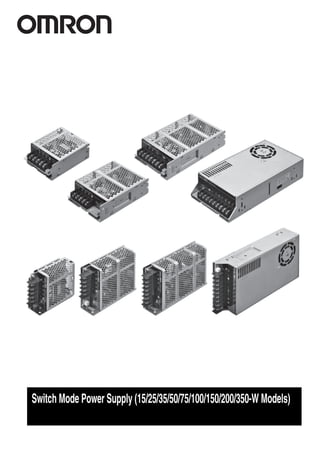
  • 1. Switch Mode Power Supply (15/25/35/50/75/100/150/200/350-W Models)
  • 2. 1 Switch Mode Power Supply (15/25/35/50/75/100/150/200/350-W Models) S8FS-C High Reliability at a Reasonable Cost. Reliable, Basic Power Supplies That Contribute to Stable Equipment Operation. • High Reliability: Enhanced abnormal overvoltage resistance and lightning surge resistance for stable operation even with an unstable input voltage. • Long Life: 105°C electrolytic capacitors are used to achieve stable quality and long life. • Wide Input Ranges: 100 to 120 VAC and 200 to 240 VAC • Global Standards: Conforms to CE (all models), Approved for cURus (all models) and CCC (15 to 150-W models). • Easy mounting to DIN Rails with Mounting Brackets (sold separately). • 3-year warranty * Refer to Period and Terms of Warranty on page 36. Product Lineup Model Number Structure Model Number Legend Note: Not all combinations are possible. Refer to List of Models in Ordering Information on page 2. Refer to Safety Precautions for All Power Supplies and Safety Precautions on page 33. Output voltage Power rating 15 W 25 W 35 W 50 W 75 W 100 W 150 W 200 W 350 W 5 V Yes Yes Yes Yes Yes Yes Yes Yes Yes 12 V Yes Yes Yes Yes Yes Yes Yes Yes Yes 15 V Yes Yes Yes Yes Yes Yes Yes --- --- 24 V Yes Yes Yes Yes Yes Yes Yes Yes Yes 36 V --- --- --- --- --- Yes Yes Yes Yes 48 V --- --- --- Yes Yes Yes Yes Yes Yes S8FS-C (1) (2) (3) (1) Power Rating (2) Output Voltage Code Power rating 015 15 W 025 25 W 035 35 W 050 50 W 075 75 W 100 100 W 150 150 W 200 200 W 350 350 W Code Output voltage 05 5 V 12 12 V 15 15 V 24 24 V 36 36 V 48 48 V (3) Terminal Block Direction Code Terminal Block Direction Blank Models with terminal block facing upward J Models with terminal block facing forward
  • 3. S8FS-C 2 Ordering Information List of Models Note: For details on normal stock models, contact your nearest OMRON representative. Note: You can use brackets that are sold separately to mount the Power Supplies to DIN Rail. Refer to Mounting Brackets (Order Separately) on page 26. *1. The range for compliance with EC Directives and safety standards (UL, EN, etc.) is 100 to 240 VAC (85 to 264 VAC). *2. The range for compliance with EC Directives and safety standards (UL, EN, etc.) is 100 to 120 VAC (85 to 132 VAC) or 200 to 240 VAC (176 to 264 VAC). *3. The range for compliance with EC Directives and safety standards (UL, EN, etc.) is 100 to 120 VAC (90 to 132 VAC) or 200 to 240 VAC (180 to 264 VAC). Power rating Input voltage Output voltage (VDC) Output current Built-in fan Model with terminal block facing upward Model with terminal block facing forward 15 W 100 to 240 VAC (allowable range: 85 to 264 VAC or 120 to 370 VDC *1) 5 V 3 A None --- S8FS-C01505J 12 V 1.3 A S8FS-C01512J 15 V 1 A S8FS-C01515J 24 V 0.7 A S8FS-C01524J 25 W 5 V 5 A S8FS-C02505 S8FS-C02505J 12 V 2.1 A S8FS-C02512 S8FS-C02512J 15 V 1.7 A S8FS-C02515 S8FS-C02515J 24 V 1.1 A S8FS-C02524 S8FS-C02524J 35 W 5 V 7 A S8FS-C03505 S8FS-C03505J 12 V 3 A S8FS-C03512 S8FS-C03512J 15 V 2.4 A S8FS-C03515 S8FS-C03515J 24 V 1.5 A S8FS-C03524 S8FS-C03524J 50 W 5 V 10 A S8FS-C05005 S8FS-C05005J 12 V 4.2 A S8FS-C05012 S8FS-C05012J 15 V 3.4 A S8FS-C05015 S8FS-C05015J 24 V 2.2 A S8FS-C05024 S8FS-C05024J 48 V 1.1 A S8FS-C05048 S8FS-C05048J 75 W 5 V 14 A S8FS-C07505 S8FS-C07505J 12 V 6.2 A S8FS-C07512 S8FS-C07512J 15 V 5 A S8FS-C07515 S8FS-C07515J 24 V 3.2 A S8FS-C07524 S8FS-C07524J 48 V 1.6 A S8FS-C07548 S8FS-C07548J 100 W 100 to 120 VAC, 200 to 240 VAC (allowable range: 85 to 132 VAC, 176 to 264 VAC, or 248 to 373 VDC (Select with the switch.) *2) 5 V 20 A S8FS-C10005 S8FS-C10005J 12 V 8.5 A S8FS-C10012 S8FS-C10012J 15 V 7 A S8FS-C10015 S8FS-C10015J 24 V 4.5 A S8FS-C10024 S8FS-C10024J 36 V 2.8 A S8FS-C10036 S8FS-C10036J 48 V 2.3 A S8FS-C10048 S8FS-C10048J 150 W 100 to 120 VAC, 200 to 240 VAC (allowable range: 90 to 132 VAC, 180 to 264 VAC, or 254 to 373 VDC (Select with the switch.) *3) 5 V 26 A S8FS-C15005 S8FS-C15005J 12 V 12.5 A S8FS-C15012 S8FS-C15012J 15 V 10 A S8FS-C15015 S8FS-C15015J 24 V 6.5 A S8FS-C15024 S8FS-C15024J 36 V 4.3 A S8FS-C15036 S8FS-C15036J 48 V 3.3 A S8FS-C15048 S8FS-C15048J 200 W 5 V 40 A S8FS-C20005 S8FS-C20005J 12 V 17 A S8FS-C20012 S8FS-C20012J 24 V 8.8 A S8FS-C20024 S8FS-C20024J 36 V 5.9 A S8FS-C20036 S8FS-C20036J 48 V 4.43 A S8FS-C20048 S8FS-C20048J 350 W 5 V 60 A Yes S8FS-C35005 S8FS-C35005J 12 V 29 A S8FS-C35012 S8FS-C35012J 24 V 14.6 A S8FS-C35024 S8FS-C35024J 36 V 9.7 A S8FS-C35036 S8FS-C35036J 48 V 7.32 A S8FS-C35048 S8FS-C35048J
  • 4. S8FS-C 3 Ratings, Characteristics, and Functions * Refer to Conditions on page 12. Power rating 15 W Item Output voltage 5 V 12 V 15 V 24 V Efficiency * 115 VAC input 80% typ. 84% typ. 84% typ. 85% typ. 230 VAC input 81% typ. 84% typ. 86% typ. 87% typ. Input Voltage range * Single phase 85 to 264 VAC, 120 to 370 VDC (The L terminal for the DC input is the positive side and safety standards do not apply.) (Derating is required according to the input voltage. Refer to Derating Curves on page 18.) Frequency * 50 /60 Hz (47 to 450 Hz) Current * 115 VAC input 0.3 A typ. 230 VAC input 0.19 A typ. Power factor --- Leakage current 115 VAC input 0.05 mA 0.05 mA 0.05 mA 0.05 mA 230 VAC input 0.10 mA 0.10 mA 0.10 mA 0.10 mA Inrush current * (for a cold start at 25°) 115 VAC input 16 A typ. 230 VAC input 32 A typ. Output Rated Output Current 3 A 1.3 A 1 A 0.7 A Voltage adjustment range * −10% to 10% (with V. ADJ) Ripple & Noise voltage * 100 to 240 VAC input 30 mVp-p max. 30 mVp-p max. 40 mVp-p max. 30 mVp-p max. Input variation influence * 0.5% max. Load variation influence * 1.0% max. Temperature vari- ation influence 100 to 240 VAC input 0.03%/°C max. Startup time * 115 VAC input 490 ms typ. 500 ms typ. 470 ms typ. 480 ms typ. 230 VAC input 470 ms typ. 480 ms typ. 450 ms typ. 460 ms typ. Hold time * 115 VAC input 14 ms typ. 16 ms typ. 18 ms typ. 15 ms typ. 230 VAC input 83 ms typ. 87 ms typ. 92 ms typ. 79 ms typ. Addi- tional func- tions Overload protection Yes, automatic reset Overvoltage protection * Yes, 115% or higher of rated output voltage, power shut off (shut off the input voltage and turn on the input again) Overheat protection No Series operation Yes (For up to 2 Power Supplies, external diodes are required.) Parallel operation No (However, backup operation is possible, external diodes are required.) Remote sensing No Remote control No Output indicator Yes (LED: Green) Insula- tion Withstand voltage 3 kVAC for 1 min. (between all input terminals and output terminals) current cutoff 20 mA 2 kVAC for 1 min. (between all input terminals and PE terminals) current cutoff 20 mA 1 kVAC for 1 min. (between all output terminals and PE terminals) current cutoff 20 mA Insulation resistance 100 Ω min. (between all output terminals and all input terminals/PE terminals) at 500 VDC Envi- ronment Ambient operating temperature −20 to 60°C (Derating is required according to the temperature. Refer to Derating Curves on page 17.) (with no condensation or icing) Storage temperature −40 to 85°C (with no condensation or icing) Ambient operating humidity 20% to 90% (Storage humidity: 10% to 95%) Vibration resistance 10 to 55 Hz, 0.375-mm half amplitude for 2 h each in X, Y, and Z directions 10 to 500 Hz, 0.26-mm half amplitude for 1 h each in X, Y, and Z directions Shock resistance 150 m/s2 , 3 times each in ±X, ±Y, ±Z directions Reliabil- ity MTBF * 135,000 hrs min. Life expectancy * 10 years min. Con- struc- tion Dimensions (W×H×D) Refer to Dimensions on page 23. Weight 150 g max. Cooling fan No Degree of protection --- Stan- dards Harmonic current emissions Conforms to EN 61000-3-2, GB17625.1 EMI Conducted Emis- sions Conforms to EN 61204-3 Class B, EN 55011 Class B, GB9254 Radiated Emis- sions Conforms to EN 61204-3 Class B, EN 55011 Class B, GB9254 EMS Conforms to EN 61204-3 high severity levels Safety Standards Approved Standards UL : cURus UL 60950-1 (Recognition) OVC II Pol2 CSA: cURus C22.2 No60950-1 CCC: GB4943 Conformed Standards EN: EN 60950-1 OVC II Pol2 Marine Standards No SEMI No
  • 5. S8FS-C 4 * Refer to Conditions on page 12. Power rating 25 W Item Output volt- age 5 V 12 V 15 V 24 V Efficiency * 115 VAC input 80% typ. 84% typ. 84% typ. 86% typ. 230 VAC input 82% typ. 86% typ. 87% typ. 88% typ. Input Voltage range * Single phase 85 to 264 VAC, 120 to 370 VDC (The L terminal for the DC input is the positive side and safety standards do not apply.) (Derating is required according to the input voltage. Refer to Derating Curves on page 18.) Frequency * 50 /60 Hz (47 to 450 Hz) Current * 115 VAC input 0.48 A typ. 230 VAC input 0.3 A typ. Power factor --- Leakage current 115 VAC input 0.10 mA 0.10 mA 0.10 mA 0.10 mA 230 VAC input 0.20 mA 0.20 mA 0.20 mA 0.20 mA Inrush current * (for a cold start at 25°) 115 VAC input 16 A typ. 230 VAC input 32 A typ. Output Rated Output Current 5 A 2.1 A 1.7 A 1.1 A Voltage adjustment range * −10% to 10% (with V. ADJ) Ripple & Noise voltage * 100 to 240 VAC input 20 mVp-p max. 20 mVp-p max. 30 mVp-p max. 50 mVp-p max. Input variation influence * 0.5% max. Load variation influence * 1.0% max. Temperature vari- ation influence 100 to 240 VAC input 0.03%/°C max. Startup time * 115 VAC input 390 ms typ. 340 ms typ. 400 ms typ. 360 ms typ. 230 VAC input 360 ms typ. 350 ms typ. 400 ms typ. 360 ms typ. Hold time * 115 VAC input 17 ms typ. 22 ms typ. 23 ms typ. 21 ms typ. 230 VAC input 103 ms typ. 113 ms typ. 117 ms typ. 112 ms typ. Addi- tional func- tions Overload protection Yes, automatic reset Overvoltage protection * Yes, 115% or higher of rated output voltage, power shut off (shut off the input voltage and turn on the input again) Overheat protection No Series operation Yes (For up to 2 Power Supplies, external diodes are required.) Parallel operation No (However, backup operation is possible, external diodes are required.) Remote sensing No Remote control No Output indicator Yes (LED: Green) Insula- tion Withstand voltage 3 kVAC for 1 min. (between all input terminals and output terminals) current cutoff 20 mA 2 kVAC for 1 min. (between all input terminals and PE terminals) current cutoff 20 mA 1 kVAC for 1 min. (between all output terminals and PE terminals) current cutoff 20 mA Insulation resistance 100 MΩ min. (between all output terminals and all input terminals/PE terminals) at 500 VDC Envi- ronment Ambient operating temperature −20 to 60°C (Derating is required according to the temperature. Refer to Derating Curves on page 17.) (with no condensation or icing) Storage temperature −40 to 85°C (with no condensation or icing) Ambient operating humidity 20% to 90% (Storage humidity: 10% to 95%) Vibration resistance 10 to 55 Hz, 0.375-mm half amplitude for 2 h each in X, Y, and Z directions 10 to 500 Hz, 0.26-mm half amplitude for 1 h each in X, Y, and Z directions Shock resistance 150 m/s2 , 3 times each in ±X, ±Y, ±Z directions Reliabil- ity MTBF * 135,000 hrs min. Life expectancy * 10 years min. Con- struc- tion Dimensions (W×H×D) Refer to Dimensions on pages 20 and 23. Weight 250 g max. Cooling fan No Degree of protection --- Stan- dards Harmonic current emissions Conforms to EN 61000-3-2, GB17625.1 EMI Conducted Emissions Conforms to EN 61204-3 Class B, EN 55011 Class B, GB9254 Radiated Emissions Conforms to EN 61204-3 Class B, EN 55011 Class B, GB9254 EMS Conforms to EN 61204-3 high severity levels Safety Standards Approved Standards UL : cURus UL 60950-1 (Recognition) OVC II Pol2 CSA: cURus C22.2 No60950-1 CCC: GB4943 Conformed Standards EN: EN 60950-1 OVC II Pol2 Marine Standards No SEMI No
  • 6. S8FS-C 5 * Refer to Conditions on page 12. Power rating 35 W Item Output voltage 5 V 12 V 15 V 24 V Efficiency * 115 VAC input 81% typ. 83% typ. 84% typ. 87% typ. 230 VAC input 81% typ. 84% typ. 84% typ. 87% typ. Input Voltage range * Single phase 85 to 264 VAC, 120 to 370 VDC (The L terminal for the DC input is the positive side and safety standards do not apply.) (Derating is required according to the input voltage. Refer to Derating Curves on page 18.) Frequency * 50 /60 Hz (47 to 450 Hz) Current * 115 VAC input 0.66 A typ. 230 VAC input 0.41 A typ. Power factor --- Leakage current 115 VAC input 0.15 mA 0.15 mA 0.15 mA 0.15 mA 230 VAC input 0.30 mA 0.25 mA 0.25 mA 0.25 mA Inrush current * (for a cold start at 25°) 115 VAC input 16 A typ. 230 VAC input 32 A typ. Output Rated Output Current 7 A 3 A 2.4 A 1.5 A Voltage adjustment range * −10% to 10% (with V. ADJ) Ripple & Noise voltage * 100 to 240 VAC input 80 mVp-p max. 90 mVp-p max. 90 mVp-p max. 80 mVp-p max. Input variation influence * 0.5% max. Load variation influence * 1.0% max. Temperature vari- ation influence 100 to 240 VAC input 0.03%/°C max. Startup time * 115 VAC input 750 ms typ. 750 ms typ. 760 ms typ. 770 ms typ. 230 VAC input 700 ms typ. 690 ms typ. 710 ms typ. 720 ms typ. Hold time * 115 VAC input 13 ms typ. 14 ms typ. 14 ms typ. 15 ms typ. 230 VAC input 74 ms typ. 75 ms typ. 75 ms typ. 79 ms typ. Addi- tional func- tions Overload protection Yes, automatic reset Overvoltage protection * Yes, 115% or higher of rated output voltage, power shut off (shut off the input voltage and turn on the input again) Overheat protection No Series operation Yes (For up to 2 Power Supplies, external diodes are required.) Parallel operation No (However, backup operation is possible, external diodes are required.) Remote sensing No Remote control No Output indicator Yes (LED: Green) Insula- tion Withstand voltage 3 kVAC for 1 min. (between all input terminals and output terminals) current cutoff 20 mA 2 kVAC for 1 min. (between all input terminals and PE terminals) current cutoff 20 mA 1 kVAC for 1 min. (between all output terminals and PE terminals) current cutoff 20 mA Insulation resistance 100 MΩ min. (between all output terminals and all input terminals/PE terminals) at 500 VDC Envi- ronment Ambient operating temperature −20 to 60°C (Derating is required according to the temperature. Refer to Derating Curves on page 17.) (with no condensation or icing) Storage temperature −40 to 85°C (with no condensation or icing) Ambient operating humidity 20% to 90% (Storage humidity: 10% to 95%) Vibration resistance 10 to 55 Hz, 0.375-mm half amplitude for 2 h each in X, Y, and Z directions 10 to 500 Hz, 0.26-mm half amplitude for 1 h each in X, Y, and Z directions Shock resistance 150 m/s2 , 3 times each in ±X, ±Y, ±Z directions Reliabil- ity MTBF * 135,000 hrs min. Life expectancy * 10 years min. Con- struc- tion Dimensions (W×H×D) Refer to Dimensions on pages 20 and 23. Weight 250 g max. Cooling fan No Degree of protection --- Stan- dards Harmonic current emissions Conforms to EN 61000-3-2, GB17625.1 EMI Conducted Emissions Conforms to EN 61204-3 Class B, EN 55011 Class B, GB9254 Radiated Emissions Conforms to EN 61204-3 Class B, EN 55011 Class B, GB9254 EMS Conforms to EN 61204-3 high severity levels Safety Standards Approved Standards UL : cURus UL 60950-1 (Recognition) OVC II Pol2 CSA: cURus C22.2 No60950-1 CCC: GB4943 Conformed Standards EN: EN 60950-1 OVC II Pol2 Marine Standards No SEMI No
  • 7. S8FS-C 6 * Refer to Conditions on page 12. Power rating 50 W Item Output voltage 5 V 12 V 15 V 24 V 48 V Efficiency * 115 VAC input 79% typ. 83% typ. 84% typ. 86% typ. 87% typ. 230 VAC input 80% typ. 84% typ. 85% typ. 86% typ. 87% typ. Input Voltage range * Single phase 85 to 264 VAC, 120 to 370 VDC (The L terminal for the DC input is the positive side and safety standards do not apply.) (Derating is required according to the input voltage. Refer to Derating Curves on page 18.) Frequency * 50 /60 Hz (47 to 450 Hz) Current * 115 VAC input 0.97 A typ. 230 VAC input 0.59 A typ. Power factor --- Leakage current 115 VAC input 0.25 mA 0.25 mA 0.25 mA 0.25 mA 0.25 mA 230 VAC input 0.60 mA 0.55 mA 0.55 mA 0.55 mA 0.55 mA Inrush current * (for a cold start at 25°) 115 VAC input 16 A typ. 230 VAC input 32 A typ. Output Rated Output Current 10 A 4.2 A 3.4 A 2.2 A 1.1 A Voltage adjustment range * −10% to 10% (with V. ADJ) Ripple & Noise voltage * 100 to 240 VAC input 80 mVp-p max. 110 mVp-p max. 100 mVp-p max. 100 mVp-p max. 80 mVp-p max. Input variation influence * 0.5% max. Load variation influence * 1.0% max. Temperature vari- ation influence 100 to 240 VAC input 0.03%/°C max. Startup time * 115 VAC input 730 ms typ. 730 ms typ. 710 ms typ. 710 ms typ. 770 ms typ. 230 VAC input 680 ms typ. 670 ms typ. 610 ms typ. 640 ms typ. 690 ms typ. Hold time * 115 VAC input 12 ms typ. 14 ms typ. 14 ms typ. 14 ms typ. 14 ms typ. 230 VAC input 71 ms typ. 77 ms typ. 78 ms typ. 77 ms typ. 80 ms typ. Addi- tional func- tions Overload protection Yes, automatic reset Overvoltage protection * Yes, 115% or higher of rated output voltage, power shut off (shut off the input voltage and turn on the input again) Overheat protection No Series operation Yes (For up to 2 Power Supplies, external diodes are required.) Parallel operation No (However, backup operation is possible, external diodes are required.) Remote sensing No Remote control No Output indicator Yes (LED: Green) Insula- tion Withstand voltage 3 kVAC for 1 min. (between all input terminals and output terminals) current cutoff 20 mA 2 kVAC for 1 min. (between all input terminals and PE terminals) current cutoff 20 mA 1 kVAC for 1 min. (between all output terminals and PE terminals) current cutoff 20 mA Insulation resistance 100 MΩ min. (between all output terminals and all input terminals/PE terminals) at 500 VDC Envi- ronment Ambient operating temperature −20 to 60°C (Derating is required according to the temperature. Refer to Derating Curves on page 17.) (with no condensation or icing) Storage temperature −40 to 85°C (with no condensation or icing) Ambient operating humidity 20% to 90% (Storage humidity: 10% to 95%) Vibration resistance 10 to 55 Hz, 0.375-mm half amplitude for 2 h each in X, Y, and Z directions 10 to 500 Hz, 0.26-mm half amplitude for 1 h each in X, Y, and Z directions Shock resistance 150 m/s2 , 3 times each in ±X, ±Y, ±Z directions Reliabil- ity MTBF * 135,000 hrs min. Life expectancy * 10 years min. Con- struc- tion Dimensions (W×H×D) Refer to Dimensions on pages 20 and 24. Weight 300 g max. Cooling fan No Degree of protection --- Stan- dards Harmonic current emissions Conforms to EN 61000-3-2, GB17625.1 EMI Conducted Emissions Conforms to EN 61204-3 Class B, EN 55011 Class B, GB9254 Radiated Emissions Conforms to EN 61204-3 Class B, EN 55011 Class B, GB9254 EMS Conforms to EN 61204-3 high severity levels Safety Standards Approved Standards UL : cURus UL 60950-1 (Recognition) OVC II Pol2 CSA: cURus C22.2 No60950-1 CCC: GB4943 Conformed Standards EN: EN 60950-1 OVC II Pol2 Marine Standards No SEMI No
  • 8. S8FS-C 7 * Refer to Conditions on page 12. Power rating 75 W Item Output voltage 5 V 12 V 15 V 24 V 48 V Efficiency * 115 VAC input 75% typ. 83% typ. 84% typ. 87% typ. 88% typ. 230 VAC input 77% typ. 83% typ. 84% typ. 87% typ. 87% typ. Input Voltage range * Single phase 85 to 264 VAC, 120 to 370 VDC (The L terminal for the DC input is the positive side and safety standards do not apply.) (Derating is required according to the input voltage. Refer to Derating Curves on page 18.) Frequency * 50 /60 Hz (47 to 450 Hz) Current * 115 VAC input 1.4 A typ. 230 VAC input 0.83 A typ. Power factor --- Leakage current 115 VAC input 0.25 mA 0.25 mA 0.25 mA 0.25 mA 0.25 mA 230 VAC input 0.60 mA 0.60 mA 0.60 mA 0.60 mA 0.60 mA Inrush current * (for a cold start at 25°) 115 VAC input 16 A typ. 230 VAC input 32 A typ. Output Rated Output Current 14 A 6.2 A 5 A 3.2 A 1.6 A Voltage adjustment range * −10% to 10% (with V. ADJ) Ripple & Noise voltage * 100 to 240 VAC input 110 mVp-p max. 90 mVp-p max. 110 mVp-p max. 140 mVp-p max. 70 mVp-p max. Input variation influence * 0.5% max. Load variation influence * 1.0% max. Temperature vari- ation influence 100 to 240 VAC input 0.03%/°C max. Startup time * 115 VAC input 750 ms typ. 720 ms typ. 730 ms typ. 750 ms typ. 700 ms typ. 230 VAC input 710 ms typ. 680 ms typ. 690 ms typ. 690 ms typ. 730 ms typ. Hold time * 115 VAC input 12 ms typ. 13 ms typ. 13 ms typ. 14 ms typ. 15 ms typ. 230 VAC input 75 ms typ. 74 ms typ. 74 ms typ. 76 ms typ. 78 ms typ. Addi- tional func- tions Overload protection Yes, automatic reset Overvoltage protection * Yes, 115% or higher of rated output voltage, power shut off (shut off the input voltage and turn on the input again) Overheat protection No Series operation Yes (For up to 2 Power Supplies, external diodes are required.) Parallel operation No (However, backup operation is possible, external diodes are required.) Remote sensing No Remote control No Output indicator Yes (LED: Green) Insula- tion Withstand voltage 3 kVAC for 1 min. (between all input terminals and output terminals) current cutoff 20 mA 2 kVAC for 1 min. (between all input terminals and PE terminals) current cutoff 20 mA 1 kVAC for 1 min. (between all output terminals and PE terminals) current cutoff 20 mA Insulation resistance 100 MΩ min. (between all output terminals and all input terminals/PE terminals) at 500 VDC Envi- ronment Ambient operating temperature −20 to 60°C (Derating is required according to the temperature. Refer to Derating Curves on page 17.) (with no condensation or icing) Storage temperature −40 to 85°C (with no condensation or icing) Ambient operating humidity 20% to 90% (Storage humidity: 10% to 95%) Vibration resistance 10 to 55 Hz, 0.375-mm half amplitude for 2 h each in X, Y, and Z directions 10 to 500 Hz, 0.26-mm half amplitude for 1 h each in X, Y, and Z directions Shock resistance 150 m/s2 , 3 times each in ±X, ±Y, ±Z directions Reliabil- ity MTBF * 135,000 hrs min. Life expectancy * 10 years min. Con- struc- tion Dimensions (W×H×D) Refer to Dimensions on pages 21 and 24. Weight 350 g max. Cooling fan No Degree of protection --- Stan- dards Harmonic current emissions Conforms to EN 61000-3-2, GB17625.1 EMI Conducted Emissions Conforms to EN 61204-3 Class B, EN 55011 Class B, GB9254 Radiated Emissions Conforms to EN 61204-3 Class B, EN 55011 Class B, GB9254 EMS Conforms to EN 61204-3 high severity levels Safety Standards Approved Standards UL : cURus UL 60950-1 (Recognition) OVC II Pol2 CSA: cURus C22.2 No60950-1 CCC: GB4943 Conformed Standards EN: EN 60950-1 OVC II Pol2 Marine Standards No SEMI No
  • 9. S8FS-C 8 * Refer to Conditions on page 12. Power rating 100 W Item Output voltage 5 V 12 V 15 V 24 V 36 V 48 V Efficiency * 115 VAC input 80% typ. 82% typ. 83% typ. 85% typ. 86% typ. 87% typ. 230 VAC input 81% typ. 83% typ. 84% typ. 87% typ. 87% typ. 88% typ. Input Voltage range * Single phase 85 to 132 VAC, 176 to 264 VAC, 248 to 373 VDC Select with the switch. (The L terminal for the DC input is the positive side and safety standards do not apply.) (Derating is required according to the input voltage. Refer to Derating Curves on page 18.) Frequency * 50 /60 Hz (47 to 450 Hz) Current * 115 VAC input 2 A typ. 230 VAC input 1.1 A typ. Power factor --- Leakage current 115 VAC input 0.35 mA 0.35 mA 0.35 mA 0.35 mA 0.40 mA 0.40 mA 230 VAC input 0.60 mA 0.55 mA 0.60 mA 0.50 mA 0.60 mA 0.60 mA Inrush current * (for a cold start at 25°) 115 VAC input 32 A typ. 230 VAC input 32 A typ. Output Rated Output Current 20 A 8.5 A 7 A 4.5 A 2.8 A 2.3 A Voltage adjustment range * −10% to 10% (with V. ADJ) Ripple & Noise voltage * 100 to 120 VAC/200 to 240 VAC input 100 mVp-p max. 70 mVp-p max. 120 mVp-p max. 90 mVp-p max. 120 mVp-p max. 50 mVp-p max. Input variation influence * 0.5% max. Load variation influence * 1.0% max. Temperature vari- ation influence 100 to 120 VAC/200 to 240 VAC input 0.03%/°C max. Startup time * 115 VAC input 740 ms typ. 310 ms typ. 360 ms typ. 350 ms typ. 320 ms typ. 380 ms typ. 230 VAC input 710 ms typ. 540 ms typ. 450 ms typ. 380 ms typ. 480 ms typ. 580 ms typ. Hold time * 115 VAC input 23 ms typ. 37 ms typ. 36 ms typ. 34 ms typ. 36 ms typ. 34 ms typ. 230 VAC input 29 ms typ. 40 ms typ. 39 ms typ. 39 ms typ. 41 ms typ. 38 ms typ. Addi- tional func- tions Overload protection Yes, automatic reset Overvoltage protection * Yes, 115% or higher of rated output voltage, power shut off (shut off the input voltage and turn on the input again) Overheat protection No Series operation Yes (For up to 2 Power Supplies, external diodes are required.) Parallel operation No (However, backup operation is possible, external diodes are required.) Remote sensing No Remote control No Output indicator Yes (LED: Green) Insula- tion Withstand voltage 3 kVAC for 1 min. (between all input terminals and output terminals) current cutoff 20 mA 2 kVAC for 1 min. (between all input terminals and PE terminals) current cutoff 20 mA 1 kVAC for 1 min. (between all output terminals and PE terminals) current cutoff 20 mA Insulation resistance 100 MΩ min. (between all output terminals and all input terminals/PE terminals) at 500 VDC Envi- ronment Ambient operating temperature −20 to 60°C (Derating is required according to the temperature. Refer to Derating Curves on page 17.) (with no condensation or icing) Storage temperature −40 to 85°C (with no condensation or icing) Ambient operating humidity 20% to 90% (Storage humidity: 10% to 95%) Vibration resistance 10 to 55 Hz, 0.375-mm half amplitude for 2 h each in X, Y, and Z directions 10 to 500 Hz, 0.26-mm half amplitude for 1 h each in X, Y, and Z directions Shock resistance 150 m/s2 , 3 times each in ±X, ±Y, ±Z directions Reliabil- ity MTBF * 135,000 hrs min. Life expectancy * 10 years min. Con- struc- tion Dimensions (W×H×D) Refer to Dimensions on pages 21 and 24. Weight 400 g max. Cooling fan No Degree of protection --- Stan- dards Harmonic current emissions Conforms to EN 61000-3-2, GB17625.1 EMI Conducted Emissions Conforms to EN 61204-3 Class B, EN 55011 Class B, GB9254 Radiated Emissions Conforms to EN 61204-3 Class B, EN 55011 Class B, GB9254 EMS Conforms to EN 61204-3 high severity levels Safety Standards Approved Standards UL : cURus UL 60950-1 (Recognition) OVC II Pol2 CSA: cURus C22.2 No60950-1 CCC: GB4943 Conformed Standards EN: EN 60950-1 OVC II Pol2 Marine Standards No SEMI No
  • 10. S8FS-C 9 * Refer to Conditions on page 12. Power rating 150 W Item Output voltage 5 V 12 V 15 V 24 V 36 V 48 V Efficiency * 115 VAC input 81% typ. 84% typ. 85% typ. 86% typ. 86% typ. 87% typ. 230 VAC input 82% typ. 85% typ. 86% typ. 87% typ. 87% typ. 88% typ. Input Voltage range * Single phase 90 to 132 VAC , Single phase 180 to 264 VAC , 254 to 373 VDC Select with the switch. (The L terminal for the DC input is the positive side and safety standards do not apply.) (Derating is required according to the input voltage. Refer to Derating Curves on page 18.) Frequency * 50 /60 Hz (47 to 450 Hz) Current * 115 VAC input 2.8 A typ. 230 VAC input 1.6 A typ. Power factor --- Leakage current 115 VAC input 0.50 mA 0.50 mA 0.50 mA 0.50 mA 0.40 mA 0.50 mA 230 VAC input 0.75 mA 0.75 mA 0.75 mA 0.70 mA 0.60 mA 0.70 mA Inrush current * (for a cold start at 25°) 115 VAC input 32 A typ. 230 VAC input 32 A typ. Output Rated Output Current 26 A 12.5 A 10 A 6.5 A 4.3 A 3.3 A Voltage adjustment range * −10% to 10% (with V. ADJ) Ripple & Noise voltage * 100 to 120 VAC/200 to 240 VAC input 50 mVp-p max. 90 mVp-p max. 110 mVp-p max. 100 mVp-p max. 200 mVp-p max. 120 mVp-p max. Input variation influence * 0.5% max. Load variation influence * 1.0% max. Temperature vari- ation influence 100 to 120 VAC/200 to 240 VAC input 0.03%/°C max. Startup time * 115 VAC input 770 ms typ. 730 ms typ. 740 ms typ. 770 ms typ. 730 ms typ. 760 ms typ. 230 VAC input 750 ms typ. 720 ms typ. 730 ms typ. 760 ms typ. 720 ms typ. 750 ms typ. Hold time * 115 VAC input 29 ms typ. 24 ms typ. 27 ms typ. 23 ms typ. 23 ms typ. 24 ms typ. 230 VAC input 35 ms typ. 30 ms typ. 31 ms typ. 28 ms typ. 29 ms typ. 29 ms typ. Addi- tional func- tions Overload protection Yes, automatic reset Overvoltage protection * Yes, 115% or higher of rated output voltage, power shut off (shut off the input voltage and turn on the input again) Overheat protection No Series operation Yes (For up to 2 Power Supplies, external diodes are required.) Parallel operation No (However, backup operation is possible, external diodes are required.) Remote sensing No Remote control No Output indicator Yes (LED: Green) Insula- tion Withstand voltage 3 kVAC for 1 min. (between all input terminals and output terminals) current cutoff 20 mA 2 kVAC for 1 min. (between all input terminals and PE terminals) current cutoff 20 mA 1 kVAC for 1 min. (between all output terminals and PE terminals) current cutoff 20 mA Insulation resistance 100 MΩ min. (between all output terminals and all input terminals/PE terminals) at 500 VDC Envi- ronment Ambient operating temperature −20 to 60°C (Derating is required according to the temperature. Refer to Derating Curves on page 17.) (with no condensation or icing) Storage temperature −40 to 85°C (with no condensation or icing) Ambient operating humidity 20% to 90% (Storage humidity: 10% to 95%) Vibration resistance 10 to 55 Hz, 0.375-mm half amplitude for 2 h each in X, Y, and Z directions 10 to 500 Hz, 0.26-mm half amplitude for 1 h each in X, Y, and Z directions Shock resistance 150 m/s2 , 3 times each in ±X, ±Y, ±Z directions Reliabil- ity MTBF * 135,000 hrs min. Life expectancy * 10 years min. Con- struc- tion Dimensions (W×H×D) Refer to Dimensions on pages 21 and 24. Weight 500 g max. Cooling fan No Degree of protection --- Stan- dards Harmonic current emissions Conforms to EN 61000-3-2, GB17625.1 EMI Conducted Emissions Conforms to EN 61204-3 Class B, EN 55011 Class B, GB9254 Radiated Emissions Conforms to EN 61204-3 Class B, EN 55011 Class B, GB9254 EMS Conforms to EN 61204-3 high severity levels Safety Standards Approved Standards UL : cURus UL 60950-1 (Recognition) OVC II Pol2 CSA: cURus C22.2 No60950-1 CCC: GB4943 Conformed Standards EN: EN 60950-1 OVC II Pol2 Marine Standards No SEMI No
  • 11. S8FS-C 10 * Refer to Conditions on page 12. Power rating 200 W Item Output voltage 5 V 12 V 24 V 36 V 48 V Efficiency * 115 VAC input 81% typ. 85% typ. 88% typ. 89% typ. 88% typ. 230 VAC input 82% typ. 86% typ. 88% typ. 89% typ. 89% typ. Input Voltage range * Single phase 90 to 132 VAC , Single phase 180 to 264 VAC , 254 to 373 VDC Select with the switch. (The L terminal for the DC input is the positive side and safety standards do not apply.) (Derating is required according to the input voltage. Refer to Derating Curves on page 18.) Frequency * 50 /60 Hz (47 to 450 Hz) Current * 115 VAC input 4.2 A typ. 230 VAC input 2.6 A typ. Power factor --- Leakage current 115 VAC input 0.35 mA 0.25 mA 0.40 mA 0.20 mA 0.40 mA 230 VAC input 0.60 mA 0.50 mA 0.75 mA 0.45 mA 0.80 mA Inrush current * (for a cold start at 25°) 115 VAC input 16 A typ. 230 VAC input 32 A typ. Output Rated Output Current 40 A 17 A 8.8 A 5.9 A 4.43 A Voltage adjustment range * −10% to 10% (with V. ADJ) Ripple & Noise voltage * 100 to 120 VAC/200 to 240 VAC input 60 mVp-p max. 60 mVp-p max. 110 mVp-p max. 130 mVp-p max. 120 mVp-p max. Input variation influence * 0.5% max. Load variation influence * 1.0% max. Temperature vari- ation influence 100 to 120 VAC/200 to 240 VAC input 0.03%/°C max. Startup time * 115 VAC input 620 ms typ. 630 ms typ. 580 ms typ. 630 ms typ. 620 ms typ. 230 VAC input 600 ms typ. 610 ms typ. 550 ms typ. 600 ms typ. 600 ms typ. Hold time * 115 VAC input 32 ms typ. 30 ms typ. 38 ms typ. 30 ms typ. 31 ms typ. 230 VAC input 37 ms typ. 35 ms typ. 45 ms typ. 37 ms typ. 37 ms typ. Addi- tional func- tions Overload protection Yes, automatic reset Overvoltage protection * Yes, 115% or higher of rated output voltage, power shut off (shut off the input voltage and turn on the input again) Overheat protection No Series operation Yes (For up to 2 Power Supplies, external diodes are required.) Parallel operation No (However, backup operation is possible, external diodes are required.) Remote sensing No Remote control No Output indicator Yes (LED: Green) Insula- tion Withstand voltage 3 kVAC for 1 min. (between all input terminals and output terminals) current cutoff 20 mA 2 kVAC for 1 min. (between all input terminals and PE terminals) current cutoff 20 mA 1 kVAC for 1 min. (between all output terminals and PE terminals) current cutoff 20 mA Insulation resistance 100 MΩ min. (between all output terminals and all input terminals/PE terminals) at 500 VDC Envi- ronment Ambient operating temperature −20 to 50°C (Derating is required according to the temperature. Refer to Derating Curves on page 17.) (with no condensation or icing) Storage temperature −40 to 85°C (with no condensation or icing) Ambient operating humidity 20% to 90% (Storage humidity: 10% to 95%) Vibration resistance 10 to 55 Hz, 0.375-mm half amplitude for 2 h each in X, Y, and Z directions 10 to 500 Hz, 0.26-mm half amplitude for 1 h each in X, Y, and Z directions Shock resistance 150 m/s2 , 3 times each in ±X, ±Y, ±Z directions Reliabil- ity MTBF * 135,000 hrs min. Life expectancy * 10 years min. Con- struc- tion Dimensions (W×H×D) Refer to Dimensions on pages 22 and 25. Weight 700 g max. Cooling fan No Degree of protection --- Stan- dards Harmonic current emissions --- EMI Conducted Emis- sions Conforms to EN 61204-3 Class A, EN 55011 Class A Radiated Emis- sions Conforms to EN 61204-3 Class A, EN 55011 Class A EMS Conforms to EN 61204-3 high severity levels Safety Standards Approved Standards UL : cURus UL 60950-1 (Recognition) OVC II Pol2 CSA: cURus C22.2 No60950-1 Conformed Standards EN: EN 60950-1 OVC II Pol2 Marine Standards No SEMI No
  • 12. S8FS-C 11 * Refer to Conditions on page 12. Power rating 350 W Item Output voltage 5 V 12 V 24 V 36 V 48 V Efficiency * 115 VAC input 77% typ. 83% typ. 86% typ. 87% typ. 87% typ. 230 VAC input 78% typ. 84% typ. 88% typ. 88% typ. 88% typ. Input Voltage range * Single phase 90 to 132 VAC , Single phase 180 to 264 VAC , 254 to 373 VDC Select with the switch. (The L terminal for the DC input is the positive side and safety standards do not apply.) (Derating is required according to the input voltage. Refer to Derating Curves on page 18.) Frequency * 50 /60 Hz (47 to 450 Hz) Current * 115 VAC input 6.6 A typ. 230 VAC input 3.9 A typ. Power factor --- Leakage current 115 VAC input 0.40 mA 0.40 mA 0.40 mA 0.40 mA 0.40 mA 230 VAC input 0.75 mA 0.80 mA 0.75 mA 0.80 mA 0.80 mA Inrush current * (for a cold start at 25°) 115 VAC input 16 A typ. 230 VAC input 32 A typ. Output Rated Output Current 60 A 29 A 14.6 A 9.7 A 7.32 A Voltage adjustment range * −10% to 10% (with V. ADJ) Ripple & Noise voltage * 100 to 120 VAC/200 to 240 VAC input 110 mVp-p max. 130 mVp-p max. 120 mVp-p max. 180 mVp-p max. 180 mVp-p max. Input variation influence * 0.5% max. Load variation influence * 2.0% max. 1.0% max. Temperature vari- ation influence 100 to 120 VAC/200 to 240 VAC input 0.03%/°C max. Startup time * 115 VAC input 610 ms typ. 620 ms typ. 580 ms typ. 610 ms typ. 610 ms typ. 230 VAC input 570 ms typ. 590 ms typ. 560 ms typ. 590 ms typ. 590 ms typ. Hold time * 115 VAC input 25 ms typ. 18 ms typ. 17 ms typ. 19 ms typ. 19 ms typ. 230 VAC input 31 ms typ. 25 ms typ. 23 ms typ. 25 ms typ. 24 ms typ. Addi- tional func- tions Overload protection Yes, automatic reset Overvoltage protection * Yes, 115% or higher of rated output voltage, power shut off (shut off the input voltage and turn on the input again) Overheat protection Yes, power shut off (shut off the input voltage and turn on the input again) (Overheat protection when the cooling fan is in an abnormal condition) Series operation Yes (For up to 2 Power Supplies, external diodes are required.) Parallel operation No (However, backup operation is possible, external diodes are required.) Remote sensing No Remote control No Output indicator Yes (LED: Green) Insula- tion Withstand voltage 3 kVAC for 1 min. (between all input terminals and output terminals) current cutoff 20 mA 2 kVAC for 1 min. (between all input terminals and PE terminals) current cutoff 20 mA 1 kVAC for 1 min. (between all output terminals and PE terminals) current cutoff 20 mA Insulation resistance 100 MΩ min. (between all output terminals and all input terminals/PE terminals) at 500 VDC Envi- ronment Ambient operating temperature −20 to 60°C (Derating is required according to the temperature. Refer to Derating Curves on page 17.) (with no condensation or icing) Storage temperature −40 to 85°C (with no condensation or icing) Ambient operating humidity 20% to 90% (Storage humidity: 10% to 95%) Vibration resistance 10 to 55 Hz, 0.375-mm half amplitude for 2 h each in X, Y, and Z directions 10 to 500 Hz, 0.26-mm half amplitude for 1 h each in X, Y, and Z directions Shock resistance 150 m/s2 , 3 times each in ±X, ±Y, ±Z directions Reliabil- ity MTBF * 135,000 hrs min. Life expectancy * 10 years min. Con- struc- tion Dimensions (W×H×D) Refer to Dimensions on pages 22 and 25. Weight 800 g max. Cooling fan Yes Degree of protection --- Stan- dards Harmonic current emissions --- EMI Conducted Emissions Conforms to EN 61204-3 Class A, EN 55011 Class A Radiated Emissions Conforms to EN 61204-3 Class A, EN 55011 Class A EMS Conforms to EN 61204-3 high severity levels Safety Standards Approved Standards UL : cURus UL 60950-1 (Recognition) OVC II Pol2 CSA: cURus C22.2 No60950-1 Conformed Standards EN: EN 60950-1 OVC II Pol2 Marine Standards No SEMI No
  • 13. S8FS-C 12 Conditions Inrush Current, Startup Time, and Output Hold Time Note: Twice the normal input current will flow for a redundant system. Sufficiently check the fusing characteristics of fuses and the operating characteristics of breakers and select fuses and breakers so that external fuses will not burn out or breakers will not operate due to inrush current. Ripple Noise Voltage The specified standard for the ripple voltage noise was measured with the following measurement circuit. Efficiency The value is given for the rated output voltage and rated output current. Input Voltage range Although some inverters give 50/60 Hz as the output frequency, do not use an inverter output as the power source for the Power Supply. Doing so may result in smoking or burning due to internal temperature increases in the Power Supply. If you connect a UPS to the input, do not connect one with a square wave output. Frequency Current The value is given for the rated output voltage and rated output current. Inrush current (for a cold start at 25°C) The value is given for a cold start at 25°C. Refer to Engineering Data on pages 17 to 19 for details. Output Voltage adjustment range If the output voltage adjuster (V. ADJ) is turned, the voltage will increase by 10% or more over the voltage adjustment range. When adjusting the output voltage, confirm the actual output voltage from the Power Supply and be sure that load is not damaged. Ripple & Noise voltage The value is given for the rated output voltage and rated output current. The value is for an ambient operating temperature of 25°C. Input variation influence This is the maximum variation in the output voltage when the input voltage is gradually changed within the allowable input voltage range at the rated output voltage and rated output current. Load variation influence This is the value when the output current is changed from 0 A to the rated output current while the input voltage is within the allowable input voltage. Startup time The value is given for the rated output voltage and rated output current. The value is given for a cold start at 25°C. Refer to Engineering Data on page 17 to 19 for details. Hold time The value is given for the rated output voltage and rated output current. The value is given for a cold start at 25°C. Refer to Engineering Data on page 17 to 19 for details. Additional functions Overvoltage protection Refer to Overvoltage Protection on page 19 for information on resetting the input power. Reliability MTBF The MTBF was calculated according to JEITA RCR-9102. Life expectancy Refer to Recommended Replacement Periods and Periodic Replacement for Preventive Maintenance on page 36 for details. Startup time Hold time AC input voltage AC input current Output voltage Inrush current on input application 90% 96.5% Input ON Input OFF S8FS-C Oscilloscope frequency band: 20 MHz C1 Twisted to 12 turns. C2 Load C1: 47 µF C2: 0.1 µF Coaxial cable +V −V
  • 14. S8FS-C 13 Connections Block Diagrams Voltage detection Overvoltage detection Drive control circuit +V −V DC output Rectifier/ smoothing circuit Photocoupler Overcurrent detection Noise filter Inrush current protection Fuse: 3.15 A AC (L) Input AC (N) Rectifier Smoothing circuit S8FS-C015 J (15 W) AC (L) Input AC (N) Fuse 25 W: 4 A 35 W: 3.15 A 50 W: 4 A 75 W: 5 A Voltage detection Overvoltage detection Drive control circuit +V −V DC output Rectifier/ smoothing circuit Photocoupler Overcurrent detection Noise filter Inrush current protection Rectifier Smoothing circuit S8FS-C025 (25 W) S8FS-C035 (35 W) S8FS-C050 (50 W) S8FS-C075 (75 W) Input voltage selector switch 100 to 120 VAC/ 200 to 240 VAC switching Input Fuse: 5 A Voltage detection Overvoltage detection Drive control circuit −V DC output Rectifier/ smoothing circuit Photocoupler Overcurrent detection Noise filter Inrush current protection Rectifier/ smoothing circuit +VAC (L) AC (N) S8FS-C100 (100 W)
  • 15. S8FS-C 14 Input Fuse: 5 A Voltage detection Overvoltage detection Drive control circuit −V DC output Rectifier/ smoothing circuit Photocoupler Overcurrent detection Noise filter Inrush current protection Rectifier/ smoothing circuit +VAC (L) AC (N) Input voltage selector switch 100 to 120 VAC/ 200 to 240 VAC switching S8FS-C150 (150 W) Input Fuse: 8 A Voltage detection Overvoltage detection Drive control circuit −V DC output Rectifier/ smoothing circuit Photocoupler Overcurrent detection Noise filter Inrush current protection Rectifier/ smoothing circuit +VAC (L) AC (N) Input voltage selector switch 100 to 120 VAC/ 200 to 240 VAC switching S8FS-C200 (200 W)
  • 16. S8FS-C 15 Overheating detection Fan Input Fuse: 10 A Voltage detection Overvoltage detection Drive control circuit −V DC output Rectifier/ smoothing circuit Photocoupler Overcurrent detection Noise filter Inrush current protection Rectifier/ smoothing circuit +VAC (L) AC (N) Input voltage selector switch 100 to 120 VAC/ 200 to 240 VAC switching S8FS-C35024 (350 W) Overheating detection Fan Input Fuse: 10 A Voltage detection Overvoltage detection Drive control circuit −V DC output Rectifier/ smoothing circuit Photocoupler Overcurrent detection Noise filter Inrush current protection Rectifier/ smoothing circuit +VAC (L) AC (N) Rectifier/ smoothing circuit Input voltage selector switch 100 to 120 VAC/ 200 to 240 VAC switching S8FS-C35005 (350 W) S8FS-C35012 (350 W) S8FS-C35036 (350 W) S8FS-C35048 (350 W)
  • 17. S8FS-C 16 Construction and Nomenclature Nomenclature *1. The fuse is located on the (L) side. It is not user replaceable. For a DC power input, connect the positive voltage to the L terminal. *2. This is the protective earth terminal specified in the safety standards. Always ground this terminal. *3. The 100-W, 150-W, 200-W, and 350-W models only. *4. Refer to Input Voltage Selector Switch in Safety Precautions on page 33. 15-W Models 25-W, 35-W, 50-W, and 75-W Models 100-W and 150-W Models 200-W and 350-W Models No. Name Function 1 Input terminals (L), (N) Connect the input lines to these terminals. *1 2 Protective Earth Terminal (PE)( ) Connect the ground line to this terminal. *2 3 DC output terminals (−V), (+V) Connect the load lines to these terminals. 4 Output indicator (DC ON: Green) Lit while the DC output is ON. 5 Output voltage adjuster (V. ADJ) Use to adjust the output voltage. 6 Input voltage selector switch Used to switch the input voltage. *3, *4 S8FS-C100 S8FS-C150 S8FS-C200 S8FS-C350 1 4 5 32 S8FS-C025 J S8FS-C035 J S8FS-C050 J S8FS-C075 J S8FS-C025 S8FS-C035 S8FS-C050 S8FS-C075 S8FS-C100 J S8FS-C150 J S8FS-C200 J S8FS-C350 J 1 4 5 32 1 4 5 32 6 1 4 5 3 2 6 1 4 5 3 2 6 S8FS-C015 J 1 4 5 32 1 4 5 32 6 6
  • 18. S8FS-C 17 Engineering Data Derating Curves Derating for Ambient Temperatures Note: The internal parts may occasionally deteriorate or be damaged. Use the standard mounting method only. Do not use the Power Supply in the area outside the derating curve. Power rating 15 W 25 W 35 W 50 W 75 W 100 W 150 W 200 W 350 W Output voltage 5 V (1) (2) (1) (1) (3) (4) (5) (7) (1) 12 V (1) (1) (2) (1) (6) 15 V --- --- 24 V (6) (1)36 V --- --- --- --- --- 48 V --- --- --- (1) (1) (1) (2) (3) (4) (5) (6) (7) −30 −20 −10 0 10 20 30 40 50 60 70 80 110 100 90 80 70 60 50 40 30 20 10 0 Ambient temperature (°C) Loadratio(%) −30 −20 −10 0 10 20 30 40 50 60 70 80 110 100 90 80 70 60 50 40 30 20 10 0 Ambient temperature (°C) Loadratio(%) −30 −20 −10 0 10 20 30 40 50 60 70 80 110 100 90 80 70 60 50 40 30 20 10 0 Ambient temperature (°C) Loadratio(%) −30 −20 −10 0 10 20 30 40 50 60 70 80 110 100 90 80 70 60 50 40 30 20 10 0 Ambient temperature (°C) Loadratio(%) −30 −20 −10 0 10 20 30 40 50 60 70 80 110 100 90 80 70 60 50 40 30 20 10 0 Ambient temperature (°C) Loadratio(%) −30 −20 −10 0 10 20 30 40 50 60 70 80 110 100 90 80 70 60 50 40 30 20 10 0 Ambient temperature (°C) Loadratio(%) −30 −20 −10 0 10 20 30 40 50 60 70 80 110 100 90 80 70 60 50 40 30 20 10 0 Ambient temperature (°C) Loadratio(%)
  • 19. S8FS-C 18 Derating for Input Voltages Note: The internal parts may occasionally deteriorate or be damaged. Use the standard mounting method only. Do not use the Power Supply in the area outside the derating curve. Power rating 15 W 25 W 35 W 50 W 75 W 100 W 150 W 200 W 350 W Output voltage 5 V (8) (8) (8) (8) (8) (9) (10) (11) (12) (11) (14) (11) (15) 12 V 15 V --- --- 24 V (13) (15) (11) (15)36 V --- --- --- --- --- 48 V --- --- --- (8) (8) (8) (9) (10) (11) (12) (13) (14) (15) 85 115 145 175 205 235 265 110 100 90 80 70 60 50 40 30 20 10 0 Input voltage (Vac) Loadratio(%) 85 95 105 115 125 135 110 100 90 80 70 60 50 40 30 20 10 0 Loadratio(%) Input voltage (Vac) 175 185 195 205 215 225 235 245 255 265 110 100 90 80 70 60 50 40 30 20 10 0 Loadratio(%) Input voltage (Vac) 90 100 110 120 130 140 110 100 90 80 70 60 50 40 30 20 10 0 Loadratio(%) Input voltage (Vac) 180 190 200 210 220 230 240 250 260 270 110 100 90 80 70 60 50 40 30 20 10 0 Loadratio(%) Input voltage (Vac) 90 100 110 120 130 140 110 100 90 80 70 60 50 40 30 20 10 0 Input voltage (Vac) Loadratio(%) 180 190 200 210 220 230 240 250 260 270 110 100 90 80 70 60 50 40 30 20 10 0 Loadratio(%) Input voltage (Vac) 180 190 200 210 220 230 240 250 260 270 110 100 90 80 70 60 50 40 30 20 10 0 Loadratio(%) Input voltage (Vac)
  • 20. S8FS-C 19 Overload Protection The load and the Power Supply are automatically protected from short-circuit currents and overcurrent damage by this function. Overload protection is activated if the output current rises above 105% of the rated current. When the output current returns within the rated range, the overload protection is automatically cleared. The values shown in the above diagrams are for reference only. Note: 1. If the Power Supply has been short-circuited or supplied with an overcurrent longer than 10 seconds, the internal parts of the Power Supply may occasionally deteriorate or be damaged. 2. Internal parts may possibly deteriorate or be damaged if the Power Supply is used for applications with frequent inrush current or overloading at the load end. Do not use the Power Supply for such applications. Overvoltage Protection Consider the possibility of an overvoltage and design the system so that the load will not be subjected to an excessive voltage even if the feedback circuit in the Power Supply fails. When an excessive voltage that is approximately 130% of the rated voltage or more is output, the output voltage is shut OFF, preventing damage to the load due to overvoltage. Reset the input power by turning it OFF for at least three minutes and then turning it back ON again. The values shown in the above diagrams are for reference only. Note: Do not turn ON the power again until the cause of the overvoltage has been removed. Overheat Protection (S8FS-C350 Only) If the internal temperature rises excessively as a result of fan failure or any other reason, the overheat protection circuit will operate to protect internal elements. Reset the input power by turning it OFF for at least three minutes and then turning it back ON again. Intermittent operation Output current (%) 0 10050 Outputvoltage(V) Overvoltage protection operating Variable rangeRated output voltage +10% −10% 0 V +30% (approx.) Outputvoltage(V)
  • 21. S8FS-C 20 Dimensions (Unit: mm) Power Supplies Models with Terminal Block Facing Upward 3.59.5 8.16 20.5 6.5 18 5 3.5 5 40.5 82±1 28 17.5 99±1 88.5±0.5 40±0.5 55±0.5 87±0.5 74±0.5 3.5 dia. Side: Two, M3 (Depth: 3 mm max.) Bottom: Two, M3 (Depth: 5 mm max.) Five, M3.5 35±1 3.5 dia. S8FS-C025 (25 W) Panel mounting hole dimensions Using the mounting holes in the Power Supply Using the screw holes in the Power Supply Bottom mounting Side mounting Two, M3 88.5±0.5 40±0.5 Two, 3.5 dia. 55±0.5 Two, M3 87±0.5 74±0.5 Two, 3.5 dia. 3.59.5 8.16 20.5 6.5 18 5 3.5 45.5 97±1 29 18.5 99±1 89±0.5 55±0.5 87±0.5 74±0.5 3.5 dia. 4.5 Side: Two, M3 (Depth: 3 mm max.) Bottom: Two, M3 (Depth: 5 mm max.) 3.5 dia. 36±1 Five, M3.5 55.5±0.5 S8FS-C035 (35 W) Panel mounting hole dimensions Using the mounting holes in the Power Supply Using the screw holes in the Power Supply Bottom mounting Side mounting Two, M3 89±0.5 55.5±0.5 Two, 3.5 dia. 55±0.5 Two, M3 87±0.5 74±0.5 Two, 3.5 dia. Bottom: Two, M3 (Depth: 5 mm max.) 3.5 dia. Side: Three, M3 (Depth: 6 mm max.) 3.5 dia. Five, M3.5 3.5 78 9.5 8.16 4.5 6.5 33 5.25 85.5±0.5 97±1 33±0.5 129±1 122.5±0.5 38±1 13±0.5 18±0.5 3.5 10 28.5 77±0.532 19 28.5 120±0.5 S8FS-C050 (50 W) Panel mounting hole dimensions Using the mounting holes in the Power Supply Using the screw holes in the Power Supply Bottom mounting Side mounting Two, M3 122.5±0.5 85.5±0.5 Two, 3.5 dia. 33±0.5 Three, M3 120±0.5 13±0.5 77±0.5 Three, 3.5 dia. 18±0.5 9±0.5
  • 22. S8FS-C 21 Bottom: Two, M3 (Depth: 5 mm max.) 3.5 dia. Side: Three, M3 (Depth: 6 mm max.) 3.5 dia. Seven, M3.5 3.59.5 8.16 4.5 6.5 32 5.5 88±0.5 97±1 159±1 152.5±0.5 38±1 13±0.518±0.5 3.5 10.5 28.5 78±0.5 22 24 19 28.5 150±0.5 117±0.5 S8FS-C075 (75 W) S8FS-C100 (100 W) Panel mounting hole dimensions Using the mounting holes in the Power Supply Using the screw holes in the Power Supply Bottom mounting Side mounting Two, M3 152.5±0.5 84.5±0.5 Two, 3.5 dia. 78±0.5 Three, M3 150±0.5 18±0.5 117±0.5 Three, 3.5 dia. 18±0.5 9.5±0.5 Note: The figure shows a 100-W Power Supply. A 75-W Power Supply has 5 terminals. S8FS-C150 (150 W) Panel mounting hole dimensions Using the mounting holes in the Power Supply Using the screw holes in the Power Supply Bottom mounting Side mounting Two, M3 192.5±0.5 80±0.5 Four, 3.5 dia. 120±0.5 80±0.5 Three, M3 190±0.5 13±0.5 157±0.5 Three, 3.5 dia. 18±0.5 8.5±0.5 Bottom: Four, M3 (Depth: 5 mm max.) 3.5 dia. Side: Three, M3 (Depth: 6 mm max.) Seven, M3.5 9.5 8.16 4.5 6.5 5.25 7.5 85.5±0.5 80±0.5 97 199±1 192.5±0.5 120±0.5 38±1 13±0.5 18±0.5 3.5 10 28.5 22 62 19.5 28.5 190±0.5 157±0.5 3.5
  • 23. S8FS-C 22 Bottom: Four, M4 (Depth: 5 mm max.) Side: Four, M4 (Depth: 6 mm max.) 9.5 8.16 30 50±0.5 112.5±1 150±0.5 50±1 25±0.5 (12.5) 32.5 212±1 15032.5 Nine, M3.5 S8FS-C200 (200 W) Panel mounting hole dimensions Using the screw holes in the Power Supply Bottom mounting Side mounting Four, 4.5 dia. 150±0.5 50±0.5 Four, 4.5 dia. 150±0.5 25±0.5 Bottom: Four, M4 (Depth: 5 mm max.) Side: Four, M4 (Depth: 6 mm max.) 9.5 8.16 30 34.1 50±0.5 112.5±1 150±0.5 50±1 25±0.5 (12.5) 32.5 41.5 212±1 150±0.532.5 Nine, M3.5 (1.2) S8FS-C350 (350 W) Panel mounting hole dimensions Using the screw holes in the Power Supply Bottom mounting Side mounting Four, 4.5 dia. 150±0.5 50±0.5 Four, 4.5 dia. 150±0.5 25±0.5
  • 24. S8FS-C 23 Models with Terminal Block Facing Forward Bottom: Two, M3 (Depth: 4 mm max.) 14 max. 51±1 28±1 78±1 25.4 14 55±0.5 66.5 12.5 8.75 6 7.62 2.75 Side: Two, M3 (Depth: 3 mm max.) Five, M3 S8FS-C015 J (15 W) Panel mounting hole dimensions Using the screw holes in the Power Supply Bottom mounting Side mounting Two, 3.5 dia. 55±0.5 Two, 3.5 dia. 66.5±0.5 Bottom: Two, M3 (Depth: 5 mm max.) 82±1 40±0.5 40.5 35±1 28 17.5 55±0.5 87±0.5 74±0.5188.2 9.5 99±1 20.5 5 6.5 5 3.5 (12) 3.5 Side: Two, M3 (Depth: 3 mm max.) Five, M3.5 3.5 dia. 3.5 dia. 88.5 ±0.5 S8FS-C025 J (25 W) Panel mounting hole dimensions Using the mounting holes in the Power Supply Using the screw holes in the Power Supply Bottom mounting Side mounting Two, M3 88.5±0.5 40±0.5 Two, 3.5 dia. 55±0.5 Two, M3 87±0.5 74±0.5 Two, 3.5 dia. Bottom: Two, M3 (Depth: 5 mm max.) 97±1 55.5±0.5 45.5 36±1 29 18.5 55±0.5 87±0.5 74±0.5188.2 9.5 99±1 20.5 4.5 6.5 5 3.5 3.5 Side: Two, M3 (Depth: 3 mm max.) Five, M3.5 3.5 dia. 3.5 dia. (12) 89±0.5 S8FS-C035 J (35 W) Panel mounting hole dimensions Using the mounting holes in the Power Supply Using the screw holes in the Power Supply Bottom mounting Side mounting Two, M3 89±0.5 55.5±0.5 Two, 3.5 dia. 55±0.5 Two, M3 87±0.5 74±0.5 Two, 3.5 dia.
  • 25. S8FS-C 24 Side: Three, M3 (Depth: 6 mm max.) Bottom: Two, M3 (Depth: 5 mm max.) Five, M3.5 3.5 dia. 3.5 dia. (12) 97±1 85.5±0.5 33 38±1 13±0.5 28.5 33±0.5 120±0.5 77±0.532 28.5 19 8.2 9.5 122.5±0.5 129±1 78 4.5 6.5 5.25 3.5 3.5 10 18±0.5 S8FS-C050 J (50 W) Panel mounting hole dimensions Using the mounting holes in the Power Supply Using the screw holes in the Power Supply Bottom mounting Side mounting Two, M3 122.5±0.5 85.5±0.5 Two, 3.5 dia. 33±0.5 Three, M3 120±0.5 13±0.5 77±0.5 Three, 3.5 dia. 18±0.5 9±0.5 Side: Three, M3 (Depth: 6 mm max.) Bottom: Two, M3 (Depth: 5 mm max.) Seven, M3.5 3.5 dia. 3.5 dia. (12) 97±1 84.5±0.5 32 38±1 13±0.5 28.5 150±0.5 117±0.522 28.5 19 8.2 9.5 152.5±0.5 159±1 24 4.5 6.5 5.5 3.5 3.5 78±0.5 10.5 18±0.5 S8FS-C075 J (75 W) S8FS-C100 J (100 W) Panel mounting hole dimensions Using the mounting holes in the Power Supply Using the screw holes in the Power Supply Bottom mounting Side mounting Two, M3 152.5±0.5 84.5±0.5 Two, 3.5 dia. 78±0.5 Three, M3 150±0.5 18±0.5 117±0.5 Three, 3.5 dia. 18±0.5 9.5±0.5 Note: The figure shows a 100-W Power Supply. A 75-W Power Supply has 5 terminals. Side: Three, M3 (Depth: 6 mm max.) Bottom: Four, M3 (Depth: 5 mm max.) Seven, M3.5 3.5 dia. (12) 97±1 85.5±0.5 80±0.5 38±1 13±0.5 28.5 190±0.5 157±0.522 28.5 19.5 8.2 9.5 192.5±0.5 120±0.5 199±1 62 4.5 6.5 5.25 7.5 3.5 3.5 10 18±0.5 S8FS-C150 J (150 W) Panel mounting hole dimensions Using the mounting holes in the Power Supply Using the screw holes in the Power Supply Bottom mounting Side mounting Two, M3 192.5±0.5 80±0.5 Four, 3.5 dia. 120±0.5 80±0.5 Three, M3 190±0.5 13±0.5 157±0.5 Three, 3.5 dia. 18±0.5 8.5±0.5
  • 26. S8FS-C 25 112.5±1 50±0.5 30 50±1 150±0.5 150±0.5 212±1 32.5 32.5 Side: Four, M4 (Depth: 6 mm max.) Bottom: Four, M4 (Depth: 5 mm max.) Nine, M3.5 25±0.5 (12) (12.5) 8.2 9.5 S8FS-C200 J (200 W) Panel mounting hole dimensions Using the screw holes in the Power Supply Bottom mounting Side mounting Four, 4.5 dia. 150±0.5 50±0.5 Four, 4.5 dia. 150±0.5 25±0.5 112.5±1 50±0.5 30 34.1 41.5 50±1 150±0.5 150±0.5 212±1 32.5 32.5 Side: Four, M4 (Depth: 6 mm max.) Bottom: Four, M4 (Depth: 5 mm max.) Nine, M3.5 25±0.5 (12) (12.5) (1.2) 8.2 9.5 S8FS-C350 J (350 W) Panel mounting hole dimensions Using the screw holes in the Power Supply Bottom mounting Side mounting Four, 4.5 dia. 150±0.5 50±0.5 Four, 4.5 dia. 150±0.5 25±0.5
  • 27. S8FS-C 26 Mounting Brackets (Order Separately)(Please ask your dealer for details of delivery.) Power rating Mounting direction Model 15 W DIN Rail S82Y-FSC015DIN 25 W S82Y-FSC025DIN 35 W S82Y-FSC050DIN 50 W 75 W S82Y-FSC150DIN100 W 150 W 200 W S82Y-FSC350DIN 350 W 15 W Bottom-mounting to DIN Rail S82Y-FSC015DIN-S 25 W S82Y-FSC025DIN-S 35 W S82Y-FSC035DIN-S 50 W S82Y-FSC050DIN-S 75 W S82Y-FSC100DIN-S 100 W 150 W S82Y-FSC150DIN-S 200 W Bottom-mounting with L-brackets S82Y-FSC350B (4 brackets) 350 W 4.5 (Sliding: 7.2 max.) Two, M3 5 max. (13) 5 25.5 25.5 28.7 29.2 96.7 S82Y-FSC015DIN Mounting Method Accessories (2 locations) Be sure to use the accessory screws. Mounting screw tightening torque: 0.48 to 0.59 N·m for M3 screws 3.5 (Sliding: 6.2 max.) Two, M3 5 max. (12) 5 35.2 36.2 49.5 32.5 117.7 107.5 S82Y-FSC025DIN Accessories (2 locations) Be sure to use the accessory screws. Mounting screw tightening torque: 0.48 to 0.59 N·m for M3 screws Mounting Method
  • 28. S8FS-C 27 4.5 (Sliding: 7.8 max.) M3 (35 W) M3 (50 W)50 W 50 W 35 W 50 W 35 W 35 W 5 max. (12) (12) 5 35.2 37.2 39.2 117.7 147.7 49.5 47.5 48.5 48.5 5.5 (Sliding: 8.8 max.) S82Y-FSC050DIN Accessories (2 locations) Be sure to use the accessory screws. Mounting screw tightening torque: 0.48 to 0.59 N·m for M3 screws Mounting Method 5.4 (Sliding: 7.8 max.) 150 W 150 W 150 W 75 W/100 W 75 W/100 W 75 W/100 W 5 max. (12) (12) 5 36.7 39.2 177.7 217.7 47.9 49.1 49.1 47.9 Four, M3 4.2 (Sliding: 6.6 max.) S82Y-FSC150DIN Mounting Method Accessories (4 locations) Be sure to use the accessory screws. Mounting screw tightening torque: 0.48 to 0.59 N·m for M3 screws 4.5 (Sliding: 7.2 max.) 200 W/350 W Four, M4 5 max. (12) 5 49.2 51.2 230.7 56.25 56.25 S82Y-FSC350DIN Mounting Method Accessories (4 locations) Be sure to use the accessory screws. Mounting screw tightening torque: 0.48 to 0.59 N·m for M3 screws
  • 29. S8FS-C 28 4.5 (Sliding: 7.2 max.) 53 38.75 25.5 25.5 Two, M3 (13) 28.7 87.7 79.5 47.2 S82Y-FSC015DIN-S Mounting Method Accessories (2 locations) Be sure to use the accessory screws. Mounting screw tightening torque: 0.48 to 0.59 N·m for M3 screws 3.5 (Sliding: 6.2 max.) 78.5 49.5 32.5 45.75 Two, M3 (12) 35.2 108.2 98 60.2 S82Y-FSC025DIN-S Mounting Method Accessories (2 locations) Be sure to use the accessory screws. Mounting screw tightening torque: 0.48 to 0.59 N·m for M3 screws 85.8 48.5 48.5 46.75 Two, M3 (12) 35.2 107.2 98 60.2 5.8 (Sliding: 9.3 max.) S82Y-FSC035DIN-S Mounting Method Accessories (2 locations) Be sure to use the accessory screws. Mounting screw tightening torque: 0.48 to 0.59 N·m for M3 screws
  • 30. S8FS-C 29 4.5 (Sliding: 7.2 max.) 85.5 48.5 48.5 48.75 Two, M3 (12) 35.2 138.2 98 80.2 S82Y-FSC050DIN-S Mounting Method Accessories (2 locations) Be sure to use the accessory screws. Mounting screw tightening torque: 0.48 to 0.59 N·m for M3 screws 98.8 47.9 49.1 48.75 Four, M375 W/100 W (12) 36.7 168.2 88.7 151 4.2 (Sliding: 6.9 max.) S82Y-FSC100DIN-S Mounting Method Accessories (4 locations) Be sure to use the accessory screws. Mounting screw tightening torque: 0.48 to 0.59 N·m for M3 screws 5.4 (Sliding: 7.8 max.) 98.8 47.9 48.75 Four, M4 (12) 36.7 208.2 108.7 151 49.1 S82Y-FSC150DIN-S Mounting Method Accessories (4 locations) Be sure to use the accessory screws. Mounting screw tightening torque: 1.08 to 1.32 N·m for M4 screws
  • 31. S8FS-C 30 Nine, M3.5 135 145 150 Four, M4 4.5 dia. R2.2 11.25 4.4 2 12.5 15 19.5 6.5 16.25 150± 0.5 1.8 (18.05) 135± 0.5 S82Y-FSC350B (Four Brackets) Mounting Method Accessories (4 locations) Be sure to use the accessory screws. Mounting screw tightening torque: 1.08 to 1.32 N·m for M4 screws Panel mounting hole dimensions
  • 32. S8FS-C 31 For Users of S8JC DIN Rail-mounting Power Supplies If you are using a DIN Rail-mounting S8JC-series Power Supply, you can replace it with an S8FS-C-series Power Supply with Forward-facing Terminal Block and a DIN Rail Mounting Bracket. Table of Corresponding S8JC Power Supplies and S8FS-C@J Power Supplies with DIN Rail Mounting Brackets *1. To mount an S8FS-series Power Supply to a DIN Rail, purchase a DIN Rail-mounting Bracket separately from the Power Supply. *2. Consult with your OMRON representative if you use a 15-W or 35-W S8JC-Z Power Supply with a 48-V output voltage. Power rating S8JC-Z *2 S8JC-ZS S8FS-C Power Supply DIN Rail-mounting Bracket *1 15 W S8JC-Z01505CD S8JC-ZS01505CD-AC2 ⇒ S8FS-C01505J + S82Y-FSC015DINS8JC-Z01512CD S8JC-ZS01512CD-AC2 ⇒ S8FS-C01512J S8JC-Z01524CD S8JC-ZS01524CD-AC2 ⇒ S8FS-C01524J 35 W S8JC-Z03505CD S8JC-ZS03505CD-AC2 ⇒ S8FS-C03505J + S82Y-FSC050DINS8JC-Z03512CD S8JC-ZS03512CD-AC2 ⇒ S8FS-C03512J S8JC-Z03524CD S8JC-ZS03524CD-AC2 ⇒ S8FS-C03524J 50 W S8JC-Z05005CD S8JC-ZS05005CD-AC2 ⇒ S8FS-C05005J + S82Y-FSC050DIN S8JC-Z05012CD S8JC-ZS05012CD-AC2 ⇒ S8FS-C05012J S8JC-Z05024CD S8JC-ZS05024CD-AC2 ⇒ S8FS-C05024J S8JC-Z05048CD --- ⇒ S8FS-C05048J 100 W S8JC-Z10005CD S8JC-ZS10005CD-AC2 ⇒ S8FS-C10005J + S82Y-FSC150DIN S8JC-Z10012CD S8JC-ZS10012CD-AC2 ⇒ S8FS-C10012J S8JC-Z10024CD S8JC-ZS10024CD-AC2 ⇒ S8FS-C10024J S8JC-Z10048CD --- ⇒ S8FS-C10048J 150 W S8JC-Z15005CD S8JC-ZS15005CD-AC2 ⇒ S8FS-C15005J + S82Y-FSC150DIN S8JC-Z15012CD S8JC-ZS15012CD-AC2 ⇒ S8FS-C15012J S8JC-Z15024CD S8JC-ZS15024CD-AC2 ⇒ S8FS-C15024J S8JC-Z15048CD --- ⇒ S8FS-C15048J 350 W S8JC-Z35005CD S8JC-ZS35005CD-AC2 ⇒ S8FS-C35005J + S82Y-FSC350DINS8JC-Z35012CD S8JC-ZS35012CD-AC2 ⇒ S8FS-C35012J S8JC-Z35024CD S8JC-ZS35024CD-AC2 ⇒ S8FS-C35024J
  • 33. S8FS-C 32 DIN Rail (Order Separately) Note: All units are in millimeters unless otherwise indicated. Note: 1. If there is a possibility that the Power Supply will be subject to vibration or shock, use a steel DIN Rail. Otherwise, metallic filings may result from aluminum abrasion. 2. If there is a possibility of the Power Supply sliding sideways, place an End Plate (PFP-M) on each end of the Power Supply. Terminal Cover (Order Separately) Terminal block direction Power rating Applicable models Terminal Cover model number Models with terminal block facing upward 25-W S82Y-FSC-C025@@ S82Y-FSC-C5 35-W S82Y-FSC-C035@@ 50-W S82Y-FSC-C050@@ 75-W S82Y-FSC-C075@@ 100-W S82Y-FSC-C100@@ S82Y-FSC-C7 150-W S82Y-FSC-C150@@ 200-W S82Y-FSC-C200@@ S82Y-FSC-C9 350-W S82Y-FSC-C350@@ Models with terminal block facing forward 15-W S82Y-FSC-C015@@J S82Y-FSC-C5MF 25-W S82Y-FSC-C025@@J S82Y-FSC-C5F 35-W S82Y-FSC-C035@@J 50-W S82Y-FSC-C050@@J 75-W S82Y-FSC-C075@@J 100-W S82Y-FSC-C100@@J S82Y-FSC-C7F 150-W S82Y-FSC-C150@@J 200-W S82Y-FSC-C200@@J S82Y-FSC-C9F 350-W S82Y-FSC-C350@@J Mounting Rail (Material: Aluminum) 4.5 15 25 25 10 10 1,000 (500)* 25 25 15 (5)* 35±0.3 7.3±0.15 27±0.15 1 * Value in parentheses are for PFP-50N. Model PFP-100N PFP-50N Mounting Rail (Material: Aluminum) 4.5 15 25 25 10 10 1,000 25 25 15 1 1.5 29.2242735±0.3 16 Model PFP-100N2 1.3 4.8 35.5 35.5 1.8 1.8 M4 spring washer 10 6.2 1 50 11.5 10 M4 × 8 panhead screw End Plate Model PFP-M
  • 34. S8FS-C 33 Safety Precautions Refer to Safety Precautions for All Power Supplies. Warning Indications Meaning of Product Safety Symbols Minor electric shock, fire, or Product failure may occasionally occur. Do not disassemble, modify, or repair the Product or touch the interior of the Product. Minor burns may occasionally occur. Do not touch the Product while power is being supplied or immediately after power is turned OFF. Fire may occasionally occur. Tighten terminal screws to the specified torque. S8FS-C015@@J: 4.25 to 5.13 lb-in (0.48 to 0.58 N·m) Other than S8FS-C015@@J: 6.55 to 7.78 lb-in (0.74 to 0.88 N·m) Minor injury due to electric shock may occasionally occur. Do not touch the terminals while power is being supplied. Minor electric shock, fire, or Product failure may occasionally occur. Do not allow any pieces of metal or conductors or any clippings or cuttings resulting from installation work to enter the Product. Ambient Operating and Storage Environments • Store the Power Supply at a temperature of −40 to 85°C and a humidity of 10% to 95%. • The internal parts may occasionally deteriorate or be damaged. Use the standard mounting method only. Do not use the Power Supply outside the derating range. • Use the Power Supply at a humidity of 20% to 90%. • Do not use the Power Supply in locations subject to direct sunlight. • Do not use the Power Supply in locations where liquids, foreign matter, or corrosive gases may enter the interior of the Power Supplies. Installation Environment • Do not use the Power Supply in locations subject to shocks or vibrations. Install the Power Supply away from contactors and other parts and devices that are sources of vibration. • Install the Power Supply well away from any sources of strong, high-frequency noise and surge. Input Voltage Selector Switch • For 100-W or higher models, the input voltage is factory-set to 200 to 240 V. To use an input voltage of 100 to 120 VAC, change the input voltage selector switch to the 100 to 120 VAC setting. To use a DC input, set the input voltage selector switch to the 200 to 240 VAC setting. • Minor electric shock may occasionally occur. Do not operate the input voltage selector switch while power is being supplied. Mounting • Take adequate measures to ensure proper heat dissipation to increase the long-term reliability of the Power Supply. • For models other than the S8FS-C350 , be sure to allow convection in the atmosphere around devices when mounting. Do not use the Power Supply in locations where the ambient temperature exceeds the range of the derating curve. • For the S8FS-C350 : Forced air cooling with a fan is used. Do not allow the ventilation holes to be blocked. The effectiveness of cooling would be reduced. • The internal parts may occasionally deteriorate or be damaged. Use the standard mounting method only. Do not use the Power Supply outside the derating range. • If you mount the Power Supply by using the screw holes provided on the chassis, the screws should preferably not penetrate beyond the exterior by more than 3 mm inside the Power Supply. If you use screws that are longer than this, make sure that they do not penetrate beyond the depth given in the dimensional diagram. Use the following tightening torque. 0.48 to 0.59 N·m for M3 screws 1.08 to 1.32 N·m for M4 screws • When cutting out holes for mounting, make sure that cuttings do not enter the interior of the Power Supplies. • The internal parts may occasionally deteriorate or be damaged due to adverse heat radiation. Do not loosen the screws on the Power Supplies. CAUTION Indicates a potentially hazardous situation which, if not avoided, may result in minor or moderate injury or in property damage. Precautions for Safe Use Supplementary comments on what to do or avoid doing, to use the product safely. Precautions for Correct Use Supplementary comments on what to do or avoid doing, to prevent failure to operate, malfunction or undesirable effect on product performance. Indicates the possibility of electric shock under specific conditions. Indicates the possibility of injuries by high temperature under specific conditions. Indicates the possibility of injuries, such as electric shock by disassembling the device, prohibiting disassembly. Indicates the instructions of unspecified general action. CAUTION Precautions for Safe Use
  • 35. S8FS-C 34 Mounting The standard mounting pattern is shown below. Mounting Pattern A The above figure shows a model with the terminal block facing upward. Mounting Pattern B The above figure shows a model with the terminal block facing upward. Mounting Pattern C *2 The above figure shows a model with the terminal block facing upward. Mounting Pattern D *2 The above figure shows a model with the terminal block facing upward. To mount the Power Supply to a DIN Rail, hook portion (A) of the Power Supply onto the DIN Rail and press the Power Supply in direction (B) until you hear it lock into place. Make sure that the catch on the Mounting Bracket is engaged with the DIN Rail. To dismount the Power Supply, pull down portion (C) with a flat-blade screwdriver and pull out the Power Supply. *1. Air flow *2. For mounting patterns C and D, a separately sold Mounting Bracket is used to mount the Power Supplies to DIN Rail. Refer to Mounting Brackets (Order Separately) on page 26 for the separately sold Mounting Brackets. Wiring • Connect the ground completely. A protective earthing terminal stipulated in safety standards is used. Electric shock or malfunction may occur if the ground is not connected completely. • Minor fire may possibly occur. Ensure that input and output terminals are wired correctly. • Do not apply more than 75 N force to the terminal block when tightening it. • Be sure to remove the sheet covering the Power Supply for machining before power-ON so that it does not interfere with heat dissipation. • Use the following material for the wires to be connected to the S8FS-C to prevent smoking or ignition caused by abnormal loads. Recommended Wire Gauges Note: The current capacity for the output terminals on the S8FS- C025 to S8FS-C350 is 25 A for each terminal. Make sure to use multiple terminals together if the current flow is higher than the current capacity for each terminal. Overload Protection • If the Power Supply has been short-circuited or supplied with an overcurrent longer than 10 seconds, the internal parts of the Power Supply may occasionally deteriorate or be damaged. • Internal parts may possibly deteriorate or be damaged if the Power Supply is used for applications with frequent inrush current or overloading at the load end. Do not use the Power Supply for such applications. 20 mm min. *1 75 mm min. 20 mm min. *1 75 mm min. 20 mm min. *1 *1 75 mm min. 20 mm min. 20 mm min. *1 S8FS-C@@@@ S8FS-C@@@@J 75 mm min. (B) (A) Terminals Model Recommended Wire Gauges Input S8FS-C015 AWG14 to 22 S8FS-C025 to S8FS-C100 AWG12 to 20 S8FS-C150 or S8FS-C200 AWG12 to 16 S8FS-C350 AWG12 Output S8FS-C015 AWG14 to 18 S8FS-C02512 to S8FS-C02524 AWG12 to 20S8FS-C03515 to S8FS-C03524 S8FS-C05024 to S8FS-C05048 S8FS-C02505 or S8FS-C03512 AWG12 to 16 S8FS-C05012 to S8FS-C05015 S8FS-C07515 to S8FS-C07548 S8FS-C10024 to S8FS-C10048 S8FS-C15036 to S8FS-C15048 S8FS-C03505 or S8FS-C05005 AWG12 S8FS-C07505 to S8FS-C07512 S8FS-C10005 to S8FS-C10015 S8FS-C15003 to S8FS-C15024 S8FS-C200 or S8FS-C350 Protective earth terminal S8FS-C015 AWG14 S8FS-C025 to S8FS-C350 AWG12 to 14 Rail stopper (C)
  • 36. S8FS-C 35 Output Voltage Adjuster (V. ADJ) • The output voltage adjuster (V. ADJ) may possibly be damaged if it is turned with unnecessary force. Do not turn the adjuster with excessive force. • After completing output voltage adjustment, be sure that the output capacity or output current does not exceed the rated output capacity or rated output current. Series Operation Two Power Supplies can be connected in series. Note: 1. If the load is short-circuited, a reverse voltage will be generated inside the Power Supply. If this occurs the Power Supply may possibly deteriorate or be damaged. Always connect a diode as shown in the figure. Select a diode having the following ratings. 2. Although Power Supplies having different specifications can be connected in series, the current flowing through the load must not exceed the smaller rated output current. Making Positive/Negative Outputs • The outputs are floating outputs (i.e., the primary circuits and secondary circuits are separated). You can therefore make positive and negative outputs by using two Power Supplies. You can make positive and negative outputs with any of the models. If positive and negative outputs are used, connect Power Supplies of the same model as shown in the following figure. (Combinations with different output capacities or output voltages can be made. However, use the lower of the two maximum rated output currents as the current to the loads.) • Depending on the model, internal circuits may be damaged due to startup failure when the power is turned ON if loads such as a servomotor or operational amplifier operate in series. Therefore, connect bypass diodes (D1, D2) as shown in the following figure. • Select a diode having the following ratings. Parallel Operation Parallel operation is not possible. Backup Operation Backup operation is possible if you use two Power Supplies of the same model. Connect diodes as shown in the following figure for backup operation. Select a diode having the following ratings. • The output voltages of Power Supplies A and B output must be set higher only by a value equivalent to the drop in forward voltages (VF) of diodes D1 and D2. • Power loss occurs equivalent to the Power Supply output current (IOUT) times the diode forward voltage (VF), and heat is generated. The diode must be cooled to ensure that its temperature is kept at or below the value indicated in the diode catalog. • There will be a power loss caused by load power and diodes. Be sure that this total power loss does not exceed the rated output power (rated output voltage times rated output current) of each Power Supply. In Case There Is No Output Voltage The possible cause for no output voltage may be that the overcurrent or overvoltage protection has operated. The internal protection circuit may operate if a large amount of surge voltage such as a lightening surge occurs while turning ON the Power Supply. In case there is no output voltage, please check the following points before contacting us: • Checking overload protection status: Check whether the load is in overload status or is short-circuited. Remove wires to load when checking. • Checking overvoltage or internal protection: Turn the power supply OFF once, and leave it OFF for at least 3 minutes. Then turn it ON again to see if this clears the condition. Charging Batteries If you connect a battery at the load, install overcurrent control and overvoltage protection circuits. Type Schottky Barrier diode Dielectric strength (VRRM) Twice the rated output voltage or above Forward current (IF) Twice the rated output current or above Type Schottky Barrier diode Dielectric strength (VRRM) Twice the rated output voltage or above Forward current (IF) Twice the rated output current or above Correct +V −V AC (L) AC (N) AC (L) AC (N) +V −V INPUT +V +V 0 V −V −V INPUT +V −V LoadLoad INPUT +V D2 D1 −V INPUT +V −V LoadLoad Load Type Schottky Barrier diode Dielectric strength (VRRM) Twice the rated output voltage or above Forward current (IF) Twice the rated output current or above +V −V AC (L) AC (N) AC (L) AC (N) +V −V Incorrect Parallel Operation +V A B D1 D2 −V +V −V Load
  • 37. S8FS-C 36 Period and Terms of Warranty Warranty Period The Power Supply warranty is valid for a period of three years from the date of shipment from the factory. Terms of Warranty The warranty is valid only for the following operating conditions. 1. Average ambient operating temperature of the Power Supply: 40°C max. 2. Average load rate: 80% max. 3. Mounting method: Standard mounting * The maximum ratings must be within the derating curve. If the Power Supply fails for reasons attributable to OMRON within the above warranty period, OMRON will repair or replace the faulty part of the Power Supply at the place of purchase or the place where the Power Supply delivered without charge. This warranty does not cover the following types of failures. Recommended Replacement Periods and Periodic Replacement for Preventive Maintenance The recommended replacement period for preventive maintenance is greatly influenced by the application environment of the Power Supply. As a guideline, the recommended replacement period is 7 to 10 years.* To prevent failures and accidents that can be caused by using a Power Supply beyond its service life, we recommend that you replace the Power Supply as early as possible within the recommended replacement period. However, bear in mind that the recommended replacement period is for reference only and does not guarantee the life of the Power Supply. Many electronic components are used in the Power Supply and the Power Supply depends on the correct operation of these components to achieve the original Power Supply functions and performance. However, the influence of the ambient temperature on aluminum electrolytic capacitors is large, and the service life is reduced by half for each 10°C rise in temperature (Arrhenius law). When the capacity reduction life of the electrolytic capacitor is reached, Power Supply failures or accidents may occur. We therefore recommend that you replace the Power Supply periodically to minimize Power Supply failures and accidents in advance. * The recommended replacement period applies under the following conditions: rated input voltage, load rate of 50% max., ambient temperature of 40°C max., and the standard mounting method. (The fan is excluded for models with fans.) This product model is designed with a service life of 10 years minimum under the above conditions. (1) Failures that result from handling or operation of the Power Supply under conditions or in environments that are not given in this document and not given in any other specifications exchanged between OMRON and the customer (2) Failures that originate in causes other than the delivered product itself (3) Failures caused by disassembly, modification, or repair of the Power Supply by anyone other than OMRON (4) Failures caused by applications or uses for which the Power Supply was not originally intended (5) Failures caused by factors that could not be anticipated with the scientific or technical knowledge available when the Power Supply was shipped (6) Failures caused by other causes for which OMRON is not responsible, such as natural disasters and other acts of God This warranty is limited to the individual product that was delivered and does not cover any secondary, subsequent, or related damages.
  • 38. Terms and Conditions of Sale 1. Offer; Acceptance. These terms and conditions (these "Terms") are deemed part of all quotes, agreements, purchase orders, acknowledgments, price lists, catalogs, manuals, brochures and other documents, whether electronic or in writing, relating to the sale of products or services (collectively, the "Products") by Omron Electronics LLC and its subsidiary companies (“Omron”). Omron objects to any terms or conditions proposed in Buyer’s purchase order or other documents which are inconsistent with, or in addition to, these Terms. 2. Prices; Payment Terms. All prices stated are current, subject to change with- out notice by Omron. Omron reserves the right to increase or decrease prices on any unshipped portions of outstanding orders. Payments for Products are due net 30 days unless otherwise stated in the invoice. 3. Discounts. Cash discounts, if any, will apply only on the net amount of invoices sent to Buyer after deducting transportation charges, taxes and duties, and will be allowed only if (i) the invoice is paid according to Omron’s payment terms and (ii) Buyer has no past due amounts. 4. Interest. Omron, at its option, may charge Buyer 1-1/2% interest per month or the maximum legal rate, whichever is less, on any balance not paid within the stated terms. 5. Orders. Omron will accept no order less than $200 net billing. 6. Governmental Approvals. Buyer shall be responsible for, and shall bear all costs involved in, obtaining any government approvals required for the impor- tation or sale of the Products. 7. Taxes. All taxes, duties and other governmental charges (other than general real property and income taxes), including any interest or penalties thereon, imposed directly or indirectly on Omron or required to be collected directly or indirectly by Omron for the manufacture, production, sale, delivery, importa- tion, consumption or use of the Products sold hereunder (including customs duties and sales, excise, use, turnover and license taxes) shall be charged to and remitted by Buyer to Omron. 8. Financial. If the financial position of Buyer at any time becomes unsatisfactory to Omron, Omron reserves the right to stop shipments or require satisfactory security or payment in advance. If Buyer fails to make payment or otherwise comply with these Terms or any related agreement, Omron may (without liabil- ity and in addition to other remedies) cancel any unshipped portion of Prod- ucts sold hereunder and stop any Products in transit until Buyer pays all amounts, including amounts payable hereunder, whether or not then due, which are owing to it by Buyer. Buyer shall in any event remain liable for all unpaid accounts. 9. Cancellation; Etc. Orders are not subject to rescheduling or cancellation unless Buyer indemnifies Omron against all related costs or expenses. 10. Force Majeure. Omron shall not be liable for any delay or failure in delivery resulting from causes beyond its control, including earthquakes, fires, floods, strikes or other labor disputes, shortage of labor or materials, accidents to machinery, acts of sabotage, riots, delay in or lack of transportation or the requirements of any government authority. 11. Shipping; Delivery. Unless otherwise expressly agreed in writing by Omron: a. Shipments shall be by a carrier selected by Omron; Omron will not drop ship except in “break down” situations. b. Such carrier shall act as the agent of Buyer and delivery to such carrier shall constitute delivery to Buyer; c. All sales and shipments of Products shall be FOB shipping point (unless oth- erwise stated in writing by Omron), at which point title and risk of loss shall pass from Omron to Buyer; provided that Omron shall retain a security inter- est in the Products until the full purchase price is paid; d. Delivery and shipping dates are estimates only; and e. Omron will package Products as it deems proper for protection against nor- mal handling and extra charges apply to special conditions. 12. Claims. Any claim by Buyer against Omron for shortage or damage to the Products occurring before delivery to the carrier must be presented in writing to Omron within 30 days of receipt of shipment and include the original trans- portation bill signed by the carrier noting that the carrier received the Products from Omron in the condition claimed. 13. Warranties. (a) Exclusive Warranty. Omron’s exclusive warranty is that the Products will be free from defects in materials and workmanship for a period of twelve months from the date of sale by Omron (or such other period expressed in writing by Omron). Omron disclaims all other warranties, express or implied. (b) Limitations. OMRON MAKES NO WARRANTY OR REPRESENTATION, EXPRESS OR IMPLIED, ABOUT NON-INFRINGEMENT, MERCHANTABIL- ITY OR FITNESS FOR A PARTICULAR PURPOSE OF THE PRODUCTS. BUYER ACKNOWLEDGES THAT IT ALONE HAS DETERMINED THAT THE PRODUCTS WILL SUITABLY MEET THE REQUIREMENTS OF THEIR INTENDED USE. Omron further disclaims all warranties and responsibility of any type for claims or expenses based on infringement by the Products or oth- erwise of any intellectual property right. (c) Buyer Remedy. Omron’s sole obli- gation hereunder shall be, at Omron’s election, to (i) replace (in the form originally shipped with Buyer responsible for labor charges for removal or replacement thereof) the non-complying Product, (ii) repair the non-complying Product, or (iii) repay or credit Buyer an amount equal to the purchase price of the non-complying Product; provided that in no event shall Omron be responsi- ble for warranty, repair, indemnity or any other claims or expenses regarding the Products unless Omron’s analysis confirms that the Products were prop- erly handled, stored, installed and maintained and not subject to contamina- tion, abuse, misuse or inappropriate modification. Return of any Products by Buyer must be approved in writing by Omron before shipment. Omron Compa- nies shall not be liable for the suitability or unsuitability or the results from the use of Products in combination with any electrical or electronic components, circuits, system assemblies or any other materials or substances or environ- ments. Any advice, recommendations or information given orally or in writing, are not to be construed as an amendment or addition to the above warranty. See http://www.omron247.com or contact your Omron representative for pub- lished information. 14. Limitation on Liability; Etc. OMRON COMPANIES SHALL NOT BE LIABLE FOR SPECIAL, INDIRECT, INCIDENTAL, OR CONSEQUENTIAL DAMAGES, LOSS OF PROFITS OR PRODUCTION OR COMMERCIAL LOSS IN ANY WAY CONNECTED WITH THE PRODUCTS, WHETHER SUCH CLAIM IS BASED IN CONTRACT, WARRANTY, NEGLIGENCE OR STRICT LIABILITY. Further, in no event shall liability of Omron Companies exceed the individual price of the Product on which liability is asserted. 15. Indemnities. Buyer shall indemnify and hold harmless Omron Companies and their employees from and against all liabilities, losses, claims, costs and expenses (including attorney's fees and expenses) related to any claim, inves- tigation, litigation or proceeding (whether or not Omron is a party) which arises or is alleged to arise from Buyer's acts or omissions under these Terms or in any way with respect to the Products. Without limiting the foregoing, Buyer (at its own expense) shall indemnify and hold harmless Omron and defend or set- tle any action brought against such Companies to the extent based on a claim that any Product made to Buyer specifications infringed intellectual property rights of another party. 16. Property; Confidentiality. Any intellectual property in the Products is the exclu- sive property of Omron Companies and Buyer shall not attempt to duplicate it in any way without the written permission of Omron. Notwithstanding any charges to Buyer for engineering or tooling, all engineering and tooling shall remain the exclusive property of Omron. All information and materials supplied by Omron to Buyer relating to the Products are confidential and proprietary, and Buyer shall limit distribution thereof to its trusted employees and strictly prevent disclosure to any third party. 17. Export Controls. Buyer shall comply with all applicable laws, regulations and licenses regarding (i) export of products or information; (iii) sale of products to “forbidden” or other proscribed persons; and (ii) disclosure to non-citizens of regulated technology or information. 18. Miscellaneous. (a) Waiver. No failure or delay by Omron in exercising any right and no course of dealing between Buyer and Omron shall operate as a waiver of rights by Omron. (b) Assignment. Buyer may not assign its rights hereunder without Omron's written consent. (c) Law. These Terms are governed by the law of the jurisdiction of the home office of the Omron company from which Buyer is purchasing the Products (without regard to conflict of law princi- ples). (d) Amendment. These Terms constitute the entire agreement between Buyer and Omron relating to the Products, and no provision may be changed or waived unless in writing signed by the parties. (e) Severability. If any provi- sion hereof is rendered ineffective or invalid, such provision shall not invalidate any other provision. (f) Setoff. Buyer shall have no right to set off any amounts against the amount owing in respect of this invoice. (g) Definitions. As used herein, “including” means “including without limitation”; and “Omron Compa- nies” (or similar words) mean Omron Corporation and any direct or indirect subsidiary or affiliate thereof. Certain Precautions on Specifications and Use 1. Suitability of Use. Omron Companies shall not be responsible for conformity with any standards, codes or regulations which apply to the combination of the Product in the Buyer’s application or use of the Product. At Buyer’s request, Omron will provide applicable third party certification documents identifying ratings and limitations of use which apply to the Product. This information by itself is not sufficient for a complete determination of the suitability of the Prod- uct in combination with the end product, machine, system, or other application or use. Buyer shall be solely responsible for determining appropriateness of the particular Product with respect to Buyer’s application, product or system. Buyer shall take application responsibility in all cases but the following is a non-exhaustive list of applications for which particular attention must be given: (i) Outdoor use, uses involving potential chemical contamination or electrical interference, or conditions or uses not described in this document. (ii) Use in consumer products or any use in significant quantities. (iii) Energy control systems, combustion systems, railroad systems, aviation systems, medical equipment, amusement machines, vehicles, safety equip- ment, and installations subject to separate industry or government regulations. (iv) Systems, machines and equipment that could present a risk to life or prop- erty. Please know and observe all prohibitions of use applicable to this Prod- uct. NEVER USE THE PRODUCT FOR AN APPLICATION INVOLVING SERIOUS RISK TO LIFE OR PROPERTY OR IN LARGE QUANTITIES WITHOUT ENSURING THAT THE SYSTEM AS A WHOLE HAS BEEN DESIGNED TO ADDRESS THE RISKS, AND THAT THE OMRON’S PRODUCT IS PROP- ERLY RATED AND INSTALLED FOR THE INTENDED USE WITHIN THE OVERALL EQUIPMENT OR SYSTEM. 2. Programmable Products. Omron Companies shall not be responsible for the user’s programming of a programmable Product, or any consequence thereof. 3. Performance Data. Data presented in Omron Company websites, catalogs and other materials is provided as a guide for the user in determining suitabil- ity and does not constitute a warranty. It may represent the result of Omron’s test conditions, and the user must correlate it to actual application require- ments. Actual performance is subject to the Omron’s Warranty and Limitations of Liability. 4. Change in Specifications. Product specifications and accessories may be changed at any time based on improvements and other reasons. It is our prac- tice to change part numbers when published ratings or features are changed, or when significant construction changes are made. However, some specifica- tions of the Product may be changed without any notice. When in doubt, spe- cial part numbers may be assigned to fix or establish key specifications for your application. Please consult with your Omron’s representative at any time to confirm actual specifications of purchased Product. 5. Errors and Omissions. Information presented by Omron Companies has been checked and is believed to be accurate; however, no responsibility is assumed for clerical, typographical or proofreading errors or omissions.
  • 39. OMRON CANADA, INC. • HEAD OFFICE Toronto, ON, Canada • 416.286.6465 • 866.986.6766 • www.omron247.com OMRON ELECTRONICS DE MEXICO • HEAD OFFICE México DF • 52.55.59.01.43.00 • 01-800-226-6766 • mela@omron.com OMRON ELECTRONICS DE MEXICO • SALES OFFICE Apodaca, N.L. • 52.81.11.56.99.20 • 01-800-226-6766 • mela@omron.com OMRON ELETRÔNICA DO BRASIL LTDA • HEAD OFFICE São Paulo, SP, Brasil • 55.11.2101.6300 • www.omron.com.br OMRON ARGENTINA • SALES OFFICE Cono Sur • 54.11.4783.5300 OMRON CHILE • SALES OFFICE Santiago • 56.9.9917.3920 OTHER OMRON LATIN AMERICA SALES 54.11.4783.5300 Authorized Distributor: T38I-E-01 09/15 Note: Specifications are subject to change. © 2015 Omron Electronics LLC Printed in U.S.A. Printed on recycled paper. Automation Control Systems • Machine Automation Controllers (MAC) • Programmable Controllers (PLC) • Operator interfaces (HMI) • Distributed I/O • Software Drives & Motion Controls • Servo & AC Drives • Motion Controllers & Encoders Temperature & Process Controllers • Single and Multi-loop Controllers Sensors & Vision • Proximity Sensors • Photoelectric Sensors • Fiber-Optic Sensors • Amplified Photomicrosensors • Measurement Sensors • Ultrasonic Sensors • Vision Sensors Industrial Components • RFID/Code Readers • Relays • Pushbuttons & Indicators • Limit and Basic Switches • Timers • Counters • Metering Devices • Power Supplies Safety • Laser Scanners • Safety Mats • Edges and Bumpers • Programmable Safety Controllers • Light Curtains • Safety Relays • Safety Interlock Switches OMRON AUTOMATION AND SAFETY • THE AMERICAS HEADQUARTERS • Chicago, IL USA • 847.843.7900 • 800.556.6766 • www.omron247.com OMRON EUROPE B.V. • Wegalaan 67-69, NL-2132 JD, Hoofddorp, The Netherlands. • +31 (0) 23 568 13 00 • www.industrial.omron.eu