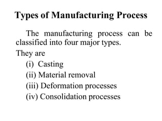
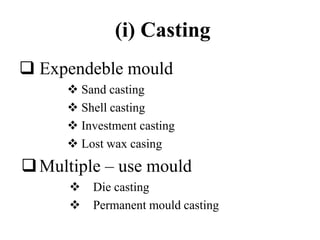
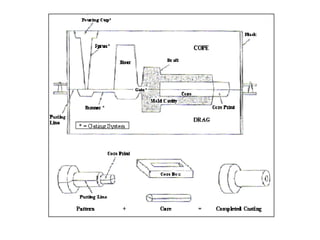
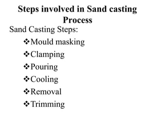
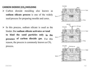
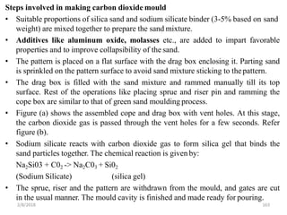
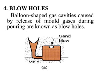
1. The document discusses various metal casting processes and sand casting in particular. It describes the basic steps in sand casting including mould making, pouring, cooling, and removal.
2. Sand is commonly used as the mould material due to its low cost. It requires binders like clay to give it strength and hold its shape. The properties of ideal moulding sand and types of sands for different applications are explained.
3. Key aspects of sand casting like advantages, disadvantages, and factors affecting the properties of moulding sand are summarized. Common tests to evaluate moulding sand quality are also mentioned.
The document discusses manufacturing processes and sand casting. It defines manufacturing as making goods by hand or machinery. Manufacturing processes are classified into casting, joining, forming, sheet metal work, plastics processing, machining, powder metallurgy, heat treatment, and assembly. Sand casting is described as producing metal parts by pouring molten metal into sand molds. Molds are made using patterns, cores, and molding machines in a foundry. Sand casting can make complex shapes and is used to produce parts in large quantities.
The document discusses the student's training report on mechanical workshop activities at Tanganyika Planting Company (TPC) Ltd, a sugar company in Tanzania. It describes TPC's history and operations. It then details the processes of pattern design, mold making with sand casting, melting brass, and pouring the molten metal into molds to produce castings. The student learned new technical skills like machining, metal fabrication, pattern design, and molding during the training.
The document discusses various types of base sands and binders used for moulding sand in metal casting. It describes silica sand, olivine sand, chromite sand, and zircon, which are commonly used as base sands. Bentonite is identified as the most commonly used clay binder for moulding sands. The properties of moulding sands such as flowability, strength, permeability, and refractoriness are also outlined. Finally, the document summarizes the typical ingredients used for different moulding sand mixtures including green sand, no-bake sand, and dry sand.
The document describes the general process for manufacturing ductile iron castings. It involves steps like raw material receipt, pattern making, core making, molding, melting, desulfurization, magnesium treatment, inoculation, pouring, cooling, shakeout, finishing, and inspection. The key goals are to produce nodular graphite structure and achieve required mechanical properties through proper process control and chemistry adjustments.
Cores are used in casting to produce hollow spaces or internal features. There are different types of cores classified by their material, production process, or placement in the mold. Dry sand cores are made separately from the mold using core sand, then baked to harden. Key steps in core production are preparing core sand, making the cores using a core box, baking the hardened cores, and finishing before placement in molds. Cores allow castings to have complex internal or recessed features.
This document discusses the process of sand casting, including:
- The typical steps of sand casting which include creating a pattern, compacting sand in a flask around the pattern, adding gates/runners/risers, and pouring molten metal.
- Key process parameters like pouring temperature and cooling rate that influence the final cast structure and properties.
- Challenges like shrinkage and ways to address it through part design like using risers and making the parting line straight.
- Considerations for part design to enable successful sand casting like geometric simplicity, generous fillets, uniform thickness, and draft angles.
The document describes the foundry processes at Porwal Auto Components Ltd. It discusses their facilities for casting, molding, melting, and testing. The company manufactures automotive and earthmoving parts using sand casting and cold box molding processes. Equipment includes induction furnaces, molding machines, sand plants, and testing facilities for chemical analysis, hardness testing, and non-destructive testing of castings.
This document discusses sand casting and provides details on:
- The types of casting sand including green sand, water glass sand, and resin sand.
- The key properties of casting sand such as strength, permeability, grain size, thermal stability, and reusability.
- Common casting defects related to issues with the sand mold like sand blow, pinholes, and sand wash.
- How to test sand properties including measuring moisture content, clay content, and grain size distribution.
This document provides information about the Metal Casting Technology course offered at VIT University. It includes details about the course faculty, textbooks, evaluation methods, and modules. The first module introduces metal casting processes, foundry industry basics, casting principles, and moulding practices. It also defines important casting terminology and properties of moulding sand like permeability and refractory properties. Common moulding equipment, patterns, and gating systems are also summarized.
Metal casting processes involve making a mold cavity using a pattern, melting and pouring metal into the mold, and allowing the metal to solidify. Key steps include preparing molds, melting and pouring metal, solidification, and inspection. Casting allows intricate shapes and wide material selection. Advantages are dimensional accuracy and surface finish can be limitations but new processes address these. Patterns are models of the final casting and come in various types depending on shape, size, and molding method. Careful pattern preparation helps minimize defects in the final casting.
This Presentation gives the information of Manufacturing process-1 of Mechanical Engineering course as per VTU Syllabus. Please write to me at: HAREESHANG@GMAIL.COM for suggestions and criticisms or visit : hareeshang.wikifoundry.com for more info.
Casting is a process where molten metal is poured into a mold and solidifies to form the desired shape. There are two main types of casting processes - those using expendable molds like sand, and those using permanent metal molds. The mold contains the cavity that defines the external shape of the part as well as any internal cores. Direction solidification is important to prevent shrinkage defects and is controlled using features like risers and chills. Properties of the final part are dependent on factors like alloy composition and solidification rate.
This document discusses sheet metal operations and core manufacturing in casting. It defines cores as models of interior surfaces that are inserted into molds. Cores require supports like chaplets to hold them in position. The document outlines core parts, types, characteristics, functions and manufacturing. Cores are made of sand or metal and can be horizontal, vertical, balanced or hanging depending on their shape and position in molds. Core boxes are used to form cores and come in types like half, split, dump and loose piece. Core prints secure cores and must withstand forces from the molten metal. The document provides equations and guidelines for proper core print sizing.
Me8392 manufacturing technology-i part-a questions & answers-Yuga Aravind Kumar
The document provides definitions and explanations of various manufacturing processes and terms. It discusses different types of patterns used in casting, advantages and disadvantages of die casting, requirements of good patterns, functions of cores, and lost wax casting process. It also describes arc welding equipment, features of friction welding, resistance welding process, purpose of flux, and how to avoid slag inclusions in welding. Various plastic processing methods like film blowing, compression moulding, parts made by rotational moulding, and definition of parison and degree of polymerization are also summarized.
Manufacturing Technology 1 full unit notesGopinath Guru
The document provides information on various metal casting processes and their working principles. It discusses sand casting process which uses expandable sand molds and involves steps of making the mold, pouring molten metal, solidification and breaking the mold. Other casting processes mentioned are permanent mold casting, die casting and investment casting. It also describes mold properties, types of patterns and allowances in patterns. Testing of molds and cores is outlined.
The document discusses the casting process and its key terms. It describes the basic steps in making a casting which are (1) pattern making, (2) mould preparation including gating and risering, (3) core making, (4) melting and pouring, and (5) cleaning and inspection. It also lists some common components produced via casting such as automobile parts, aircraft turbine blades, pumps, valves and pipes. The advantages of casting include the ability to produce large and intricate shapes, suitability for mass production, uniform material properties, and low cost. Limitations include potential defects, unsuitability for small batches or thin sections.
This document provides information on the manufacturing process of metal casting. It discusses the key steps in metal casting which include mould preparation, pouring molten metal, solidification, and inspection for defects. Moulds are prepared using sand and patterns to form cavities. Molten metal is poured into the mould and allowed to solidify to form the final casting. Proper mould design and avoiding defects are important for successful casting. Metal casting allows for intricate shapes but has limitations in dimensional accuracy and surface finish compared to other processes.
This document discusses various tests used to evaluate the properties of molding sands used in foundries. It describes 11 key properties tested: specimen preparation, compression, shear, flow ability, hardness, green strength, dry strength, hot strength, collapsibility, plasticity, and lists references for further information. The tests are important for characterizing molding sands to ensure they have sufficient strength and ability to retain the mold shape during the casting process.
The document discusses the key steps in the sand casting process:
1. Creating a mechanical drawing and pattern of the part to be cast
2. Preparing molds by setting cores and positioning patterns
3. Pouring molten metal and allowing it to solidify in the mold
4. Removing the casting and performing trimming and finishing operations
The document provides an overview of the sand casting process from pattern making to final inspection and packaging for shipment.
casting introduction, steps involved in casting,gating system,gates,pattern, patterns allowances, advantages and disadvantages of casting process and applications of casting process
The document describes the casting process and its key terms. It discusses the main steps: pattern making, mould preparation including gating and risering, core making, melting and pouring, and cleaning and inspection. It provides details on each step and describes how a mould is made by packing sand around a pattern. Common components produced by casting are also listed, such as automobile and aircraft parts. Advantages include the ability to make complex shapes easily and economically, while limitations include potential defects and inferior properties compared to other processes.
Unit 1 manufacturing technology I Metal casting processGopinath Guru
This document discusses various metal casting processes and techniques. It covers topics like sand casting, pattern making, molding sand properties, core making, and casting defects. Sand casting involves pouring molten metal into an expandable sand mold and allowing it to solidify. Different types of sand and patterns are used depending on the application. Properties of molding sand like permeability and strength are important. Cores are used to create internal cavities and angles in castings.
The document discusses various aspects of casting processes and patterns used in casting. It describes the casting process where molten metal is poured into a mold and solidifies. It then discusses different types of patterns used including single piece, split piece, loose piece, and sweep patterns. The key considerations for pattern materials are also summarized such as wood, metal, plastic and their advantages. Pattern allowances including shrinkage, draft, machining and distortion allowances are explained.
This document provides information on the casting process, including definitions, components, steps, and considerations. Some key points:
1. The casting process involves pouring molten metal into a mold patterned after the part, allowing it to solidify, and removing the part from the mold. Important considerations are metal flow, solidification, and mold material.
2. Components include patterns, molds, cores, and gating systems. Steps are pattern making, molding, melting, pouring, solidification, cleaning, and inspection.
3. Patterns are modified replicas of the object and include allowances for shrinkage, draft, and machining. Common pattern materials are wood, metal, and plastic
1. The document discusses various metal casting processes and sand casting. It describes the key steps in sand casting like mould making, pouring, cooling, and removal.
2. Sand is commonly used as the mould material due to its low cost. It requires a binder like clay to hold its shape. The document outlines important properties of moulding sand like grain size, permeability, strength.
3. Various tests are described to evaluate properties like moisture content, clay content, permeability and strength. The document provides details of the procedures for conducting these tests.
This document discusses the properties and composition of molding materials used in metal casting. It outlines 11 key properties molding materials must have including refractoriness, permeability, green strength, dry strength, and collapsibility. Common molding materials are described as sand, with silica sand being most widely used. The composition of molding sand is outlined as consisting of a base sand like silica, a binder like clay, and moisture. Factors that affect mold quality like moisture content, grain size, and shape are also summarized.
This document provides an overview of different casting processes, focusing on sand casting. It discusses two main categories of casting processes: expendable mold processes, where the mold is destroyed to remove the part, and permanent mold processes, where the mold can be reused. For sand casting, it describes the production sequence, including pattern making, mold making using various types of sand, and the casting operation. It also discusses other expendable mold processes like shell molding, vacuum molding, expanded polystyrene casting, and investment casting.
very useful for 1st year engineering student who studying the workshop manufacturing practices. in this ppt pdf all about casting viz. pattern, mould, different type of sand, riser design, different casting process and defects in casting is given in short.
The document describes the steps involved in the sand casting process. It begins by making a pattern from materials like wood, metal, or plastic. Sand mixtures are then prepared for molding and cores. The mold and cores are formed using the pattern. Metal is melted and poured into the mold, where it solidifies into a casting. The casting is then cleaned, inspected for defects, heat treated, and inspected again before shipping. Various types of patterns, materials for patterns, and allowances made on patterns are also described.
Presentation study of manufacturing process in hmt machine tools limited.docxAbu Sufyan Malik
Manufacturing is the production of products for use or sale using labour and machines, tools, chemical and biological processing, or formulation, and is the essence of secondary industry. The term may refer to a range of human activity, from handicraft to high-tech, but is most commonly applied to industrial design, in which raw materials from primary industry are transformed into finished goods on a large scale. Such finished goods may be sold to other manufacturers for the production of other more complex products or distributed via the tertiary industry to end users and consumers (usually through wholesalers, who in turn sell to retailers, who then sell them to individual customers).
Manufacturing engineering or manufacturing process are the steps through which raw materials are transformed into a final product. The manufacturing process begins with the product design, and materials specification from which the product is made. These materials are then modified through manufacturing processes to become the required part.
The manufacturing sector is closely connected with engineering and industrial design. Examples of major manufacturers in North America include General Motors Corporation, General Cast Parts. Examples in Europe include Volkswagen Group, Siemens, FCA and Michelin. Examples in Asia include Toyota, Yamaha, Panasonic, LG, Samsung and Tata Motors.
This document discusses various casting processes and related topics. It begins with definitions of casting and different casting processes like permanent mold casting, investment casting, centrifugal casting, continuous casting, and sand casting. For each process, it provides details on the process, applications, advantages and limitations. It also discusses topics like molding sands, furnaces used in foundries like cupolas, electric arc furnaces, and induction furnaces. The document aims to provide an overview of casting processes and technologies.
This document provides an overview of various manufacturing processes, with a focus on metal casting processes. It discusses the steps in metal casting including creating a mould, pouring molten metal, and removing the casting. It describes important casting products and the advantages and limitations of casting. Key terms related to casting like pattern, parting line, and riser are defined. Different pattern materials and allowances are also covered. Moulding materials like green sand and core sand are explained. Finally, other metal forming processes like die casting are introduced.
The document discusses casting and the casting process. Casting involves pouring liquid material into a mold to create objects. Common casting materials include metals, epoxy, concrete, and plaster. A foundry produces metal castings by melting metals and pouring them into molds. After solidification, the casting is removed from the mold. The casting process involves designing molds and patterns, melting and pouring metals, solidification and cooling, then finishing and inspecting the final casting for defects. Key aspects of casting include mold composition, gating system design, pouring parameters, and solidification properties to minimize defects during production.
The document discusses various metal casting processes and techniques. It covers topics like sand casting, pattern making, molding sand, cores, melting furnaces, and special casting processes. Sand casting is introduced as one of the most common casting methods where a sand mold is used. Key aspects covered include pattern materials and allowances, molding sand properties and testing, core types and testing, and common casting defects. Special casting techniques like shell mold casting, investment casting, and die casting are also summarized.
This document discusses manufacturing technology processes, specifically focusing on sand casting. It defines sand casting as a process for producing metal parts by pouring molten metal into a mold cavity made of sand. Key aspects covered include:
- Types of patterns used to form the mold cavity
- Materials and properties of moldsand
- Methods for making cores to create internal cavities
- Baking and curing of cores in core ovens
- Defects that can occur in sand casting and how properties of moldsand and cores can impact the casting quality.
This document discusses manufacturing technology processes, specifically focusing on sand casting. It defines sand casting as a process for producing metal parts by pouring molten metal into a mold cavity made of sand. Key aspects covered include:
- Types of patterns used to form the mold cavity
- Materials and properties of moldsand
- Methods for making cores to create internal cavities
- Baking and curing of cores in core ovens
- Defects that can occur in sand castings
This seminar report discusses shell molding, also known as shell mold casting. Some key points:
1) Shell molding uses a resin-covered sand to form molds for casting small to medium metal parts, providing better dimensional accuracy and productivity than sand casting.
2) The process involves creating a pattern, applying a heated sand-resin mixture to form a shell around the pattern, curing the shell, assembling two shell halves, and pouring molten metal to form the casting.
3) Shell molding allows casting of both ferrous and non-ferrous metals for parts requiring precision, such as gear housings and cylinder heads.
4) The sand used is finer
This document provides information on metal casting processes and patterns. It discusses the different types of patterns used such as single piece patterns, shell patterns, and wax patterns. It also covers the various pattern allowances including shrinkage allowance, machining allowance, draft allowance, and others. The document discusses the properties and types of molding sands used including green sand, dry sand, facing sand, loam sand, backing sand, parting sand and core sand. It provides details on the requirements for molding materials including refractoriness, permeability, green strength and others.
Metal casting involves pouring liquid metal into a mold to produce parts of a desired shape. The key steps are melting metal to create a liquid, pouring it into a mold to achieve a solid shape as it cools and extracts heat, and then removing the solidified part from the mold. The quality of castings depends on factors like the flow of molten metal into the mold, the solidification and cooling process, and the type of mold material used. Common casting methods include sand casting, die casting, and investment casting.
The document discusses various metal casting processes and techniques. It covers topics like sand casting, pattern making, moulding sand, cores, melting furnaces, and special casting processes. Sand casting is introduced as one of the most common casting methods where a sand mould is used. Different types of patterns and allowances are described. The properties and testing of moulding sands like green sand and dry sand are outlined. Special casting techniques like shell mould casting and investment casting that use non-sand moulds are also summarized briefly.
The document discusses various metal casting processes including sand casting, permanent mold casting, shell molding, vacuum molding, expanded polystyrene casting, investment casting, and plaster mold casting. It describes the key steps, advantages, and disadvantages of each process. Sand casting is the most widely used process due to ability to cast nearly all alloys and produce castings in a wide range of sizes.
Batteries -Introduction – Types of Batteries – discharging and charging of battery - characteristics of battery –battery rating- various tests on battery- – Primary battery: silver button cell- Secondary battery :Ni-Cd battery-modern battery: lithium ion battery-maintenance of batteries-choices of batteries for electric vehicle applications.
Fuel Cells: Introduction- importance and classification of fuel cells - description, principle, components, applications of fuel cells: H2-O2 fuel cell, alkaline fuel cell, molten carbonate fuel cell and direct methanol fuel cells.
Redefining brain tumor segmentation: a cutting-edge convolutional neural netw...IJECEIAES
Medical image analysis has witnessed significant advancements with deep learning techniques. In the domain of brain tumor segmentation, the ability to
precisely delineate tumor boundaries from magnetic resonance imaging (MRI)
scans holds profound implications for diagnosis. This study presents an ensemble convolutional neural network (CNN) with transfer learning, integrating
the state-of-the-art Deeplabv3+ architecture with the ResNet18 backbone. The
model is rigorously trained and evaluated, exhibiting remarkable performance
metrics, including an impressive global accuracy of 99.286%, a high-class accuracy of 82.191%, a mean intersection over union (IoU) of 79.900%, a weighted
IoU of 98.620%, and a Boundary F1 (BF) score of 83.303%. Notably, a detailed comparative analysis with existing methods showcases the superiority of
our proposed model. These findings underscore the model’s competence in precise brain tumor localization, underscoring its potential to revolutionize medical
image analysis and enhance healthcare outcomes. This research paves the way
for future exploration and optimization of advanced CNN models in medical
imaging, emphasizing addressing false positives and resource efficiency.
Using recycled concrete aggregates (RCA) for pavements is crucial to achieving sustainability. Implementing RCA for new pavement can minimize carbon footprint, conserve natural resources, reduce harmful emissions, and lower life cycle costs. Compared to natural aggregate (NA), RCA pavement has fewer comprehensive studies and sustainability assessments.
Electric vehicle and photovoltaic advanced roles in enhancing the financial p...IJECEIAES
Climate change's impact on the planet forced the United Nations and governments to promote green energies and electric transportation. The deployments of photovoltaic (PV) and electric vehicle (EV) systems gained stronger momentum due to their numerous advantages over fossil fuel types. The advantages go beyond sustainability to reach financial support and stability. The work in this paper introduces the hybrid system between PV and EV to support industrial and commercial plants. This paper covers the theoretical framework of the proposed hybrid system including the required equation to complete the cost analysis when PV and EV are present. In addition, the proposed design diagram which sets the priorities and requirements of the system is presented. The proposed approach allows setup to advance their power stability, especially during power outages. The presented information supports researchers and plant owners to complete the necessary analysis while promoting the deployment of clean energy. The result of a case study that represents a dairy milk farmer supports the theoretical works and highlights its advanced benefits to existing plants. The short return on investment of the proposed approach supports the paper's novelty approach for the sustainable electrical system. In addition, the proposed system allows for an isolated power setup without the need for a transmission line which enhances the safety of the electrical network
Understanding Inductive Bias in Machine LearningSUTEJAS
This presentation explores the concept of inductive bias in machine learning. It explains how algorithms come with built-in assumptions and preferences that guide the learning process. You'll learn about the different types of inductive bias and how they can impact the performance and generalizability of machine learning models.
The presentation also covers the positive and negative aspects of inductive bias, along with strategies for mitigating potential drawbacks. We'll explore examples of how bias manifests in algorithms like neural networks and decision trees.
By understanding inductive bias, you can gain valuable insights into how machine learning models work and make informed decisions when building and deploying them.
International Conference on NLP, Artificial Intelligence, Machine Learning an...gerogepatton
International Conference on NLP, Artificial Intelligence, Machine Learning and Applications (NLAIM 2024) offers a premier global platform for exchanging insights and findings in the theory, methodology, and applications of NLP, Artificial Intelligence, Machine Learning, and their applications. The conference seeks substantial contributions across all key domains of NLP, Artificial Intelligence, Machine Learning, and their practical applications, aiming to foster both theoretical advancements and real-world implementations. With a focus on facilitating collaboration between researchers and practitioners from academia and industry, the conference serves as a nexus for sharing the latest developments in the field.
Introduction- e - waste – definition - sources of e-waste– hazardous substances in e-waste - effects of e-waste on environment and human health- need for e-waste management– e-waste handling rules - waste minimization techniques for managing e-waste – recycling of e-waste - disposal treatment methods of e- waste – mechanism of extraction of precious metal from leaching solution-global Scenario of E-waste – E-waste in India- case studies.
ACEP Magazine edition 4th launched on 05.06.2024Rahul
This document provides information about the third edition of the magazine "Sthapatya" published by the Association of Civil Engineers (Practicing) Aurangabad. It includes messages from current and past presidents of ACEP, memories and photos from past ACEP events, information on life time achievement awards given by ACEP, and a technical article on concrete maintenance, repairs and strengthening. The document highlights activities of ACEP and provides a technical educational article for members.
Embedded machine learning-based road conditions and driving behavior monitoringIJECEIAES
Car accident rates have increased in recent years, resulting in losses in human lives, properties, and other financial costs. An embedded machine learning-based system is developed to address this critical issue. The system can monitor road conditions, detect driving patterns, and identify aggressive driving behaviors. The system is based on neural networks trained on a comprehensive dataset of driving events, driving styles, and road conditions. The system effectively detects potential risks and helps mitigate the frequency and impact of accidents. The primary goal is to ensure the safety of drivers and vehicles. Collecting data involved gathering information on three key road events: normal street and normal drive, speed bumps, circular yellow speed bumps, and three aggressive driving actions: sudden start, sudden stop, and sudden entry. The gathered data is processed and analyzed using a machine learning system designed for limited power and memory devices. The developed system resulted in 91.9% accuracy, 93.6% precision, and 92% recall. The achieved inference time on an Arduino Nano 33 BLE Sense with a 32-bit CPU running at 64 MHz is 34 ms and requires 2.6 kB peak RAM and 139.9 kB program flash memory, making it suitable for resource-constrained embedded systems.
Harnessing WebAssembly for Real-time Stateless Streaming PipelinesChristina Lin
Traditionally, dealing with real-time data pipelines has involved significant overhead, even for straightforward tasks like data transformation or masking. However, in this talk, we’ll venture into the dynamic realm of WebAssembly (WASM) and discover how it can revolutionize the creation of stateless streaming pipelines within a Kafka (Redpanda) broker. These pipelines are adept at managing low-latency, high-data-volume scenarios.
4. Types of Manufacturing Process
The manufacturing process can be
classified into four major types.
They are
(i) Casting
(ii) Material removal
(iii) Deformation processes
(iv) Consolidation processes
5. (i) Casting
Expendeble mould
Sand casting
Shell casting
Investment casting
Lost wax casing
Multiple – use mould
Die casting
Permanent mould casting
6. (ii) Material removal
Mechanical machining
Turning
Milling
Drilling
Boring
Sawing
Non – traditional machining
Etching
Electro polishing
Electro discharge machining
Water jet machining
Abrasive jet machining
Laser beam machining
7. (iii) Deformation process
Hot bulk forming
Forging
Rolling
Extrusion
Cold forming
Wire drawing
Swaging
Roll forming
Deep drawing
10. 1. Metal casting processes
A casting may be defined as a “metal
object obtained by allowing molten
metal to solidify in a mould” , the
shape of the object being determined by
the shape of the mould cavity.
Casting (or) foundry is a process of
forming metallic products by melting
the metal, pouring in to a cavity known
as the mould, and allowing it to solidify.
11.
12. When it is removed from the mould,
it will be same shapes as the mould.
Many parts and components are made
by casting, including
carburetors, engine
cameras,
blocks,
crankshafts, automotive components,
agricultural equipments, road
equipment, and pipes.
13. Advantages of casting process
Some of the reasons for the success
of the casting process are:
The most intricate of shapes, both
external and internal, may be cast.
Extremely large, heavy metal objects
may be cast when they would be
difficult or economically impossible to
produce.
14. Because of their physical properties,
some metal can only be cast to
shape since they cannot be hot-
worked into bars, rods, plates, or
other shapes.
Construction may be simplified as a
single piece.
15. Metal casting is a process highly
adaptable to the requirements of
mass production
Some engineering properties are
obtained more favorably in cast
metals.
16. 2. Sand Casting
Sand casting is used to produce a
wide variety of metal components
with complex geometries.
These parts can vary greatly in size
and weight, ranging from a couple
ounces to several tons.
For sand casting, the most common
materials are iron, steel, brass and
aluminum.
17. With these alloys, sand casting can
produce small parts that weigh less than
one pound or large parts that weight
several tons.
It is a cost effective and efficient process
for small lot production, and yet, when
using automated equipment, it is an
effective manufacturing process for high
– volume production.
Sand casting is also common in producing
automobile components, such as engine
blocks, engine manifolds, cylinder heads,
and transmission cases.
18. Advantages
Low cost of mould materials and
equipment.
Large casting dimensions may be
obtained.
Wide variety of metals and alloys
(ferrous and non – ferrous) may be
cast (including high melting point
metals)
20. Steps involved in Sand casting
Process
Sand Casting Steps:
Mould masking
Clamping
Pouring
Cooling
Removal
Trimming
21. 1.3 Moulding Sands
Most sand casting operations use silica
sand (SiO2).
A great advantage of sand in
manufacturing applications is that sand is
inexpensive.
Sand casting is one of the few processes
that can be used for metals with high
melting temperatures such as steels,
nickel, and titanium.
A typical mixture by volume could be
89% sand, 4% water, 7% clay.
22. Uses of binders in Sand Casting
A mould must have the physical integrity
to hold its keep its shape.
Clay serves an essential purpose in the
sand casting manufacturing process, as a
binding agent to adhere the moulding
sand together.
Organic resins, (such as phenolic resins),
and inorganic bonding agents (such as
phosphate and sodium silicate), may also
be used to hold the sand together.
23. Important ingredients of Moulding
Sand
The moulding sands are Consisting
of the following ingredients.
They are
(i) Silica sand grains
(ii) Clay
(iii) Moisture
(iv) Miscellaneous materials
24. Silica is the product of the breaking up
of quartz rocks or the decomposition of
the granite.
Silica sand contains 80 to 90% of
Silicon dioxide (Sio2) .
Clay is the particles of sand that fail to
settle at a rate of 30 mm per minute,
when suspended in water.
Mostly moulding sands has different
grades of work contain 5 to 20% of
clay.
25. Moisture gives the good bonding action
of clay.
The water should be 2 to 9%
Miscellaneous materials are the
ingredients which are added to silica and
clay in moulding sand are oxide of iron,
limestone, magnesia, soda and potash.
The impurities should be below 3%.
26. Properties of moulding sand
Grain size and shape
Porosity (or) Permeability
Refractoriness
Cohesiveness (or) Strength
Adhesiveness
Plasticity
Collapsibility
27. (i) Grain size and shape
The size and shape of the grains in
the sand determine the application in
various types of foundry.
There are three different sizes of
sand grains.
• Fine
• Medium
• Coarse
28. • Fine:
Fine for small and intricate
casting.
• Medium:
Medium for bench work and
light floor works.
• Coarse:
Coarse for larger size
casting.
29. (ii) Porosity (Or) Permeability
The moulding sand must be
sufficiently porous to allow the
dissolved gases, which are evolved
When the metal freezes or
moisture present or generated with
in the moulds to be removed freely
when the moulds are poured.
30. (iii) Refractoriness
Refractoriness is the property of
withstanding the high
temperature.
It is the ability of the moulding
material to resist the temperature
of the liquid metal to be poured so
that it does not get fused with the
metal.
31. (iv) Cohesiveness (or) strength
The strength of the moulding sand
must be sufficient to permit the
mould to be formed, to the desired
shape and to retain the shape even
after the molten metal is poured in
to the mould.
32. Green Strength:
The moulding sand that contains
moisture is termed as green sand.
Dry Strength :
When the molten metal is poured in
the mould , the sand around the mould cavity is
quickly converted into dry sand, evaporates due
to the heat of the molten metal.
Hot Strength:
As soon as the moisture is eliminated,
the sand would reach at a high temperature when
the metal in still in liquid state. The strength of
the sand that is required to hold the shape of the
cavity is called hot strength.
33. (v) Adhesiveness
Sticking strength of the moulding
sand to the sides of the mould
boxes.
It is defined as the sand particles
easily attach itself with the sides
of the moulding box and give
easy of lifting and turning the box
when filled with the sand.
34. (vi) Plasticity
It is the ability to behave like a
fluid so that, when rammed, it will
flow to all portions of a mould and
park all – round the pattern and
take up the required shape.
(vii) Collapsibility
Easy to collapse after solidified
metal is to be taken out from the
mould.
35. Types of moulding sands
(i) According to the properties of
moulding sand
(i) According to the usage
36. (i) According to the properties of
moulding sand
• Natural moulding sand
• Synthetic (or) High silica sand
• Special sand
37. (ii) According to the usage
• Green sand
• Dry sand
• Loam sand
• Facing sand
• Backing sand
• System sand
• Parting sand
• Core sand
38. (i) Green sand
The sand which is in moist state
is known as green sand.
It is a mixture of silica sand
with 18 to 30% of clay having a
total water of from 6 to 8%.
39. (ii) Dry sand
After the mould is made, the
green sand has been heated then it
is called Dry sand.
This is suitable for large
casting.
40. (iii) Loam sand
It consists of fine silica sand, fine
refractories, clay, graphite, fiber and
water.
The clay content is very high in
loam sand.
41. (iv) Facing sand
It will be applied for covering
the surface of the pattern.
(v) Backing sand
It is also called ‘floor sand’.
It is used to back up the facing
sand and to fill the whole volume of
the flask.
42. (vi) System sand
The used sand is cleaned and
reactivated by the addition of water
binders and special additives.
(vii) Parting sand
It is used to keep the green sand
from sticking to the pattern and also
allow the sand on the parting surface of
the cope and drag.
44. Methods of Sand testing
(i) Moisture content test
(ii) Clay content test
(iii) Grain fitness test
(iv) Permeability test
45. (v)Strength test
• Green and Dry compression
• Green tensile
• Green and Dry shear
• Bending
(vi) Refractoriness test
(vii) Mould hardness test
46. 1. Moisture content test
Moister is defined as the amount
of water present in the moulding
sand. Low moisture content does
not develop strength properties.
High moisture content decreases
permeability.
47.
48. Moisture content test methods
Using direct reading moisture teller, the
test reaction is:
CaC2+ 2 H2O = Ca (OH)2 C2H2
The pressure of C2H2 gives the direct
reading of the water content on the
pressure gauge.
Using electrode probe devices
Employing measurements of microwave
absorption in compacted sand samples.
In using infrared heating
49. Procedure to find moisture
content moulding sand
Step 1: 20 to 50 gms of prepared sand is
placed in the pan and is heated by an
infrared heater bulb for 2 to 3
minutes.
Step 2: The moisture in the moulding
sand is thus evaporated.
Step 3 : Moulding sand is taken out of the
pan and reweighed.
50. Step 4: The percentage of moisture can be
calculated from the difference in the
weights, of the original moist and the
consequently dried sand samples.
Where
W1–Weight of the sand before drying
W2–Weight of the sand after drying
51. 2. Clay content test
Clay influences strength,
permeability and other moulding
properties.
52. Procedure to find Clay content
Step 1 : Small quantity of prepared
moulding sand was dried.
Step 2 : Separate 50 gms of dry
moulding sand and transfer wash
bottle.
Step 3 : Add 475 cc of distilled water +
25 cc of a 3% NaOH.
53. Step 4 : Agitate this mixture about 10
minutes with the help of sand stirrer.
Step 5 : Fill the wash bottle with water
up to the marker.
Step 6 : After the sand has settled for
about 10 minutes, Siphon out the
water from the wash bottle.
Step 7 : Dry the settled down sand.
54. Step 8: The clay content can be determined
from the difference in weights of the
initial and finish sand samples.
Where
W1–Weight of the sand before drying
W2–Weight of the sand after drying
55. 3. Grain Fitness Test
grain
The
distribution, grain finess
size,
are
determined with the help of the
fitness testing of moulding sands.
56.
57. 4. Permeability test
The quantity of air that
a standard
will pass
specimen
particular
through
of the
pressure
sand at a
condition is
called the permeability of the sand.
58.
59. Major parts of the permeability test
equipment
An inverted bell jar, which floats in
a water.
Specimen tube, for the purpose of
hold the equipment.
A manometer (measure the Air
pressure)
60. 5. Strength test
Measurement of strength of
moulding sands can be carried out
on the universal sand strength
testing machine.
The sands could be tested are
green sand, dry sand or core sand.
61.
62. (a) Green Compression strength
Green compression strength or
simply green strength generally refers
to the stress required to rupture the
sand specimen under compressive
loading.
The green strength of sands is
generally in the range of 30 to 160
Kpa.
63. (b) Green Shear strength
A different adapter is filled in the
universal machine so that the loading
now be made for the shearing of the
sand sample.
The stress required to shear the
specimen along the axis is then
represented as the green shear
strength.
It may vary from 10 to 50 Kpa.
64. (c) Dry strength
This test uses the standard
specimens dried between 105 and
1100 C for 2 hours.
The range of dry compression
strengths found in moulding sands
is from 140 to 1800 Kpa,
depending on the sand sample.
65. 6. Refractoriness Test
The refractoriness test is used
to ability to withstand the moulding
sand for the higher temperature
condition.
66. Steps in refractoriness test:
Step 1 : Prepare a cylindrical specimen of
sand.
Step 2 :Heating the specimen at 1500oC
for two hours.
Step 3 : Observe the changes in
dimension and appearance.
Step 4 : If the sand is good, it remains
specimen share and shows very little
expansion. If the sand is poor, specimen
will shrink and distort.
67. 7. Mould Hardness Test
Where,
P – Applied Force (N)
D – Diameter of the indentor (mm)
d –Diameter of the indentation (mm)
68.
69. Moulding Sand preparation
The preparation of sand
includes the following primary process.
(i) Mixing of sand
(ii) Tempering of sand
(iii) Sand conditioning
70. (i) Mixing of sand
Remove the all foreign matters from
sand. (nails, fans)
Screening of sand
Mechanical mixing of sand with
ingredients by using MULLER
71. (ii) Tempering of sand
Temper the mould sand ingredients.
Conditions mulling action given
until is a uniform distribution of the
ingredients occur.
72. (iii) Sand conditions
Areation process
Check whether some highly amount
of sand grains are separates (or) not in
the areation process
73. Pattern and Pattern Making
A pattern is simply the duplicate of
the component which has to be
manufactured by the casting process.
The pattern are packed into sand that is
mixed with binding agents.
The pattern is purposely made larger
than the cast part to allow for shrinkage
during cooling.
74. Sand “cores” can be inserted in the
mould to create holes and improve the
casting’s final shape.
Vent holes are created to allow hot
gases to escape during the pour.
The selection of a pattern material
depends on the side and shape of the
casting, dimensional accuracy, the
quantity of casting required.
75. Pattern Materials
The most used pattern materials has
good characteristics. There are
(i) Wood and wood materials
(ii) Metals andAlloys
(iii) Plasters
(iv) Plastic and Rubbers
(v) Waxes
76. The most wood is straight grained,
light, easy to work.
The most common wood used for
pattern is teak wood.
Metal patterns are very useful in
machine moulding.
A metal pattern is itself cast from a
wooden pattern called “master pattern”.
77. Cast iron is used for some highly
specialized types of patterns
Aluminium is probably the best all
round metal.
Plastics are now finding their place as
a modern pattern material because they
do not absorb moisture.
Gypsum cement known as plaster of
paris is also used for making patterns
are core boxes.
78. Types of Patterns
(i) Single piece pattern (or) Solid pattern.
(ii) Split pattern
(iii) Match plate pattern
(iv) Cope and Drag pattern
(v) Gated pattern
(vi) Loose – piece pattern
(vii) Sweep pattern
(viii) Skeleton pattern
(ix) Segmental pattern
(x) Shell pattern
79. (i) Single piece pattern (or) Solid
pattern.
It is are generally used for simpler
shapes and low quality production.
These type of patterns are made with
out joints, partings (or) any loose
pieces in its.
Soil temper, staffing – box and
gland of a steam engine are few
examples of casting which are made by
making solid patterns.
81. (ii) Split pattern
Split patterns are two – piece patterns made
such that each part forms a portion of the
cavity for the casting.
The upper and the lower parts of the split
pattern are accommodated in the cope and
drag portions of the mould.
The surface formed at the center line of the
pattern, is called the parting surface (or)
parting line.
Making of more parts instead two to make
completed pattern for a complicated this type
of pattern is called multi- piece pattern.
83. (iii) Match plate pattern
The match plate pattern is typically used
in high production industry runs for
casting manufacture.
A match plate pattern is a two piece
pattern representing the casting.
In the match plate pattern, however, each
of the parts are mounted on a plate.
Match plate patterns are normally used in
machine moulding.
They produce accurate castings and at
faster rates.
85. (iv) Cope and Drag pattern
The cope and drag pattern enables the
cope section of the mould and the
drag section of the mould to be
created separately and latter
assembled before the pouring of the
casting.
It is used to produce the big
castings.
87. (v) Gated pattern
In these patterns the sections are
connecting different patterns serve
as runner and gates.
That is used for mass production
systems.
Gated patterns are usually made of
Metal which increases their strength
and reduces the tendency to wrap.
88.
89. (vi) Loose – piece pattern
These loose – piece patterns are
needed, when the part is such that the
pattern cannot be removed as one
piece, even though it is split and the
line is made on more than one plane.
91. (vii) Sweep pattern
A sweep pattern is just a form, made
on a wooden board with sweeps the
shape of the casting into the sand all
around the circumference.
The sweep patterns are rotating about
the post. It is used for producing large
casting of circular sections.
93. (viii) Skeleton pattern
This is a ribbed construction with a
large number of square or rectangular
openings between the ribs which from a
skeleton outline of the pattern to be made.
The framework is filled and rammed
with clays, sand or loam and a strike-off
board known as a strickle board.
95. (ix) Segmental pattern
These type patterns are also called as
Part patterns.
They are applied to circular work such
as rings, wheel of the automobile, gears.
After ramming one section, it goes
forward to the next section for ramming,
and so on, until the entire mould
perimeter has been completed.
96.
97. (x) Shell pattern
These types of patterns are usually
made up of metal, mounted on plate
and parted along the center line, the
two sections being accurately dweled
together.
The shell pattern is used largely for
pipe works and drainage fittings.
98.
99. Thursday, February 8, 2018 99
PATTERN ALLOWANCES
A pattern is always made somewhat larger
than the final job to be produced. This excess
in dimensions is referred to as the Pattern
allowance.
Types
1. Shrinkage or Contraction allowance
2. Draft or Taper allowance
3. Machining or Finish allowance
4. Rapping or ShakingAllowance
5. Distortion or CamberAllowance
100. Thursday, February 8, 2018 100
Shrinkage or contraction allowance
Generally metals shrink in size during
solidification and cooling in the mould.
So casting becomes smaller than the pattern.
To compensate for this, the pattern should be
made larger than the casting.
The amount of compensation for shrinkage is
called the shrinkage allowance.
101. Thursday, February 8, 2018 101
Shrinkage or contraction allowance
• Liquid Shrinkage: it refers to the reduction in
volume when the metal changes from liquid state
to solid state at the solidus temperature. To account
for this shrinkage; riser, which feed the liquid metal
to the casting, are provided in the mold.
• Solid Shrinkage: it refers to the reduction in
volume caused when metal loses temperature in
solid state. To account for this, shrinkage allowance is
provided on the patterns.
102. Rate of Contraction of Various Metals
Material Dimension Shrinkage allowance
(inch/ft)
Grey Cast Iron Up to 2 feet 0.125
2 to 4 feet 0.105
over 4 feet 0.083
Cast Steel Up to 2 feet 0.251
2 feet to 6 feet 0.191
over 6 feet 0.155
Aluminum Up to 4 feet 0.155
4 feet to 6 feet 0.143
over 6 feet 0.125
Magnesium Up to 4 feet 0.173
Over 4 feet 0.155
Thursday, February 8, 2018 102
103. Draft or taper allowance
• When a pattern is drawn from a mould, there is always a
possibility of damaging the edges of the mould.
• Draft is taper made on the vertical faces of a pattern to make
easier drawing of pattern out of the mould as shown in Fig.
• The draft is expressed in millimeters per metre on a side or
in degrees.
Thursday, February 8, 2018 103
104. Thursday, February 8, 2018 104
Draft Allowances of Various Metals
Pattern material Height of the
given surface
(inch)
Draft angle
(Externalsurface)
Draft angle
(Internalsurface)
Wood 1 3.00 3.00
1 to 2 1.50 2.50
2 to 4 1.00 1.50
4 to 8 0.75 1.00
8 to 32 0.50 1.00
Metal and Plastic 1 1.50 3.00
1 to 2 1.00 2.00
2 to 4 0.75 1.00
4 to 8 0.50 1.00
8 to 32 0.50 0.75
105. Thursday, February 8, 2018 105
Machining or finish allowance
Is given due to the following reasons:
1. For removing surface roughness, Scale, slag, dirt and other
imperfections from the casting.
2. For obtaining exact dimensions on the casting.
3. To achieve desired surface finish on the casting.
The dimension of the pattern to be increased depends upon the
following factors:
1. Method of machining used (turning, grinding, boring, etc.).
2. Characteristics of metal
3. Method of casting used.
4. Size and shape of the casting.
5. Degree of finish required.
106. Thursday, February 8, 2018 106
Machining Allowances of Various Metals
Metal Dimension (inch) Allowance (inch)
Cast iron Up to 12 0.12
12 to 20 0.20
20 to 40 0.25
Cast steel Up to 6 0.12
6 to 20 0.25
20 to 40 0.30
Non ferrous Up to 8 0.09
8 to 12 0.12
12 to 40 0.16
107. Thursday, February 8, 2018 107
Rapping or Shaking Allowance
• When the pattern is shaken for easy withdrawal, the
mould cavity, hence the casting is slightly increased
in size. In order to compensate for this increase, the
pattern should be initially made slightly smaller.
• For small and medium sized castings, this allowance
can be ignored.
• Large sized and precision castings, however, shaking
allowance is to be considered.
• The amount of this allowance is given based on
previous experience.
108. Distortion or CamberAllowance
• Sometimes castings, because of their size, shape and
type of metal, tend to warp or distort during the
cooling period depending on the cooling speed.
• Expecting the amount of warpage, a pattern may be
made with allowance of warpage. It is called camber.
• For example, a U-shaped casting will be distorted
during cooling with the legs diverging, instead of
parallel as shown in fig. For compensating this
warpage, the pattern is made with the legs converged
but,as the casting cools, the legs straighten and
remain parallel.
Thursday, F
Ce
b
r
au
sa
r
ty
in8
,g
2
0
1
w
8ithout camber 109
Actual casting Pattern with camber allowance
109. Thursday, February 8, 2018 109
CORES
What is core in Casting?
A core is a body made of sand which is used to
make a cavity or a hole in a casting.
Also used to make recesses, projections,
undercuts and internal cavities.
110. Thursday, February 8, 2018 110
TYPES OF CORES
(a) According to the state of core
(i) Green sand core
(ii) Dry sand core
(b) According to the position of core in mould
(i) Horizontal core
(ii) Vertical core
(iii) Balanced core
(iv) Hanging core
(v) Drop core
111. Thursday, February 8, 2018 111
1.Green sand core
When the pattern leaves a core as a part of
the mould, then the body of sand is called
green sand core.
It is suitable only for vertical openings.
2.Dry sand core
The cores heated to 200°C to 350°C in the core
baking ovens are called dry sand cores.
These cores are commonly used.
112. 3. Horizontal core
Placed horizontally
Cylindrical in shape
Supported in core seats at both the ends.
Thursday, February 8, 2018 112
114. 5.Balacing core
Supported and balanced from its end
Require long core seat
Used when blind holes along a horizontal axis
is needed.
Thursday, February 8, 2018 114
115. 6.Hanging core
Supported at top and hang into mould
Supported by seat at top portion of drag
Used when cored casting is to be completely
moulded in drag with help of single piece solid
pattern.
Thursday, February 8, 2018 115
116. 7.Drop core
Used when a hole is not in the parting line
Hole may be above or below the parting line
Depending upon the usage it may be called as
tail core, chair core or saddle core.
Thursday, February 8, 2018 116
117. Thursday, February 8, 2018 117
Moulding Machines
Moulding machines will do the following
operations:
1.Ramming the moulding sand
2.Rapping the pattern for easy removal
3.Removing the pattern from the sand
118. Thursday, February 8, 2018 118
1.Jolting machine
Pattern is placed in the flask on the table
The table is raised to 80mm and suddenly
dropped
Table is operated pneumatically or hydraulically.
Sudden dropping of table makes the sand pack
evenly around the pattern
Mainly used for ramming horizontal surfaces on
the mould.
Operation is noisy.
120. Thursday, February 8, 2018 120
2.Squeezing machine
Moulding sand in the flask is squeezed between
the machine table and a Squeezer head.
Two types
1.Top Squeezing machine
2. Bottom Squeezing machine
121. Thursday, February 8, 2018 121
1.Top Squeezer machine
Mould board is clamped on the table
Flask is placed on the mould board
Pattern is placed inside the flask
Sand is filled up and levelled
Table is raise by table lift mechanism against
the sqeezer head
Patterns enters the sand frame and packs sand
tightly
123. Thursday, February 8, 2018 123
2.Bottom Squeezer machine
Pattern is placed on the mould table
Mould table is clamped on the ram
Table with pattern is raised against the
Squeezer head
Flask with the pattern is squeezed between
squeezer head and the table.
125. Thursday, February 8, 2018 125
3.Sand Slinger
Pattern is placed on a board
Flask is placed over it
The slinger is operated
Slinger has impeller which can be rotated with
different speeds
Impeller rotates will throw a stream of sand at
great velocity into the flask
Slinger is moved to pack sand uniformly.
129. Thursday, February 8, 2018 129
Construction:
Cylindrical shell made of 10 mm thick steel
plate.
Lined with refractory bricks inside.
Two bottom doors.
Sand bed laid over the bottom doors.
Slag hole provided above the tap hole.
Opening called tuyeres one meter above
bottom
Wind box and blower
Charging door.
130. Thursday, February 8, 2018 130
Preparation:
Previous melting cleaned
Broken bricks must be replaced
Bottom doors are closed
Sand bed sloping towards tap hole-height 200mm
Tap hole lined with clay
Slag hole is prepared
Cupola dried thoroughly
131. Thursday, February 8, 2018 131
Firing
Oil and wooden piece-placed at bottom
Air- sufficient amount is supplied
Coke-charged at several portions
Blast is turned off
More coke- upto tuyeres level
Coke-level of bed charge
Coke-burn for half an hour
Charging-at the charging door
132. Thursday, February 8, 2018 132
Charging and Melting
Pig iron and iron scrap-charged at charging door
Coke-charged alternatively
Limestone-remove impurities-thorough mixing
Pig iron to limestone ratio: 25:1
Pig iron to coke: 10:1
Iron soaked for 1 hour
Blast turned on
Molten metal-collected at sand bed
Clay plug-collected in ladles
133. Thursday, February 8, 2018 133
Molten metal-poured into moulds
Floating slag-tapped out through slag hole
Furnace charged full-repeating same procedure
Cupola shut off-by stopping air blast
Wastes-dropped down and quenched by water
Application:
Melting Cast iron
134. Thursday, February 8, 2018 134
Advantages of Cupola furnace
1.Initial cost is low
2.Simple in design
3.Requires only less floor area
4.Operations and Maintenance is simple
5.Operated continuously for many hours
135. PROCESS IN THE BLAST
FURNACE
1.Introduction of charge
2.Introduction of hot blast
3.Combustion of coke
4.Production of carbon monoxide
(reducing agent)
5. Reduction of haematite
6.Decomposition of limestone
7.Formation of slag
136. 1. Introduction of charge
The charge is introduced into the
furnace through the cup and cone
arrangement.
137. 2. Introduction of hot blast
Simultaneously a hot blast of air is
introduced into the furnace through
the tuyeres
138. 3. Combustion of coke
Coke present in the
charge burns in the hot air producing
carbon dioxide generating more heat
C + O2 → CO2 + ∆
139. 4. Production of carbon monoxide
(reducing agent)
The carbon dioxide formed
rises up and reacts with the incoming
coke forming carbon monoxide
CO2 + C → 2CO
140. 5. Reduction of haematite
Carbon monoxide formed is a
powerful reducing agent.
It reduces haematite to iron
Fe2O3+ 3CO → 2Fe + 3CO2↑
141. 6. Decomposition of limestone
limestone decomposes
Due to the heat,
forming
calcium oxide and carbon dioxide
CaCO3+ 3CO CaO + CO2↑
142. 7. Formation of slag
The quick lime (i.e. CaO) thus
formed acts as a flux and combines with
sand (an acidic impurity) converting it
into calcium silicate, an easily fusible
mass. Thus mass is called slag.
CaO + SiO2 → CaSiO3
143. The iron formed is collected at the
bottom of the furnace and the slag
forms a layer on it. It protects the
molten iron from oxidation.
The iron obtained by this process is
called pig iron. It contains carbon as
an impurity.
145. Special moulding Processes
A. Sand moulds
1. Green sand mould
2. Dry sand mould
3. Core sand mould
4. Carbon dioxide mould (CO2 mould)
5. Shell mould
6. Investment mould
7. Sweep mould
8. Full mould
B. Metal moulds
9. Gravity die casting or Permanent mould casting
10. Pressure die casting
11. Continuous casting
12. Centrifugal casting
13. Squeeze casting
21/8/420.18Thixocastingprocess 146
146. 5. SHELL MOULDING
.
147
• Shell moulding is an efficient and
economical method for producing steel
castings.
• The process was developed by Herr
Croning in Germany during World war-II
and is sometimes referred to as the
Croning shell process.
Procedure involved in making shell mould
a. A metallic pattern having the shape of
the desired casting is made in one half
from carbon steel material. Pouring
element is provided in the pattern itself
b. The metallic pattern is heated in an oven to a suitable temperature between
180 - 250°C. The pattern is taken out from the oven and sprayed with a
solution of a lubricating agent viz., silicone oil or spirit to prevent the shell
(formed in later stages) from sticking to the pattern.
c. The pattern is inverted and is placed over a box as shown in figure 3.3(b). The
box contains a mixture of dry silica sand or zircon sand and a resin binder (5%
2/8/2b0a18sedon sand weight).
147. d. The box is now inverted so that the
resin-sand mixture falls on the heated
face of the metallic pattern. The resin-
sand mixture gets heated up, softens
and sticks to the surface of the pattern.
Refer figure (c).
e. After a few seconds, the box is again
inverted to its initial position so that the
lose resin-sand mixture falls down
leaving behind a thin layer of shell on
the pattern face. Refer figure (d).
f. The pattern along with the shell is
removed from the box and placed in an
oven for a few minutes which further
hardens the shell and makes it rigid. The
shell is then stripped from the pattern
with the help of ejector pins that are
provided on the pattern. Refer figure (e).
2/8/2018 147
148. g. Another shell half is prepared in the
similar manner and both the shells are
assembled, together with the help of
bolts, clips or glues to form a mould.
The assembled part is then placed in a
box with suitable backing sand to
receive the molten metal. Refer figure
(f).
h. After the casting solidifies, it is
removed from the mould, cleaned and
finished to obtain the desired shape.
Advantages
Better surface finish and dimensional tolerances.
Reduced machining.
Requires less foundry space.
Semi-skilled operators can handle the process easily.
Shells can be stored for extended periods of time.
Disadvantages
Initially the metallic pattern has to be cast to the desired shape, size and finish.
Size and weight range of castings is limited.
Process generates noxious fumes.
2/8/2018 148
149. 6. INVESTMENT MOULD
• Investment mould also called as 'Precision casting' or 'Lost
wax process' is an ancient method of casting complex
shapes like impellers, turbine blades and other airplane
parts that are difficult to produce by other manufacturing
techniques.
The various steps involved in this process are:
Step 1 Die and Pattern making
• A wax pattern is prepared by injecting liquid wax into a pre-
fabricated die having the same geometry of the cavity of
the desired cast part. Refer figure.1.
• Several such patterns are produced in the similar manner
and then attached to a wax gate and sprue by means of
heated tools or melted wax to form a 'tree' as shown in
figure 2.
2/8/2018 149
150. a
e
o
')
Step 2 Pre-coating wax patterns
• The tree is coated by dipping into refractory slurry which is
mixture of finely ground silica flour suspended in ethyl silicat
solution (binder).
• The coated tree is sprinkled with silica sand and allowed t
dry. Refer figure 3 and 4.
Step 3 Investment
• The pre-coated tree is coated again (referred as 'investment
by dipping in a more viscous slurry made of refractory flour
(fused silica, alumina etc.) and liquid binders (colloidal silica,
sodium silicate etc.) and dusted with refractory sand.
• The process of dipping and dusting is repeated until a solid
shell of desired thickness (about 6 - 10 mm) is achieved.
Note: The first coating is composed of very fine particles
that produce a good surface finish, whereas the second
coating which is referred as 'Investment' is coarser so as
to build up the shell of desired thickness.
2/8/2018 150
151. Step 4 De-waxing '
• The tree is placed in an inverted position and heated in a oven to about 300°F. The wax
melts and drops down leaving a mould cavity that will be filled later by the molten metal.
Refer figure 5.
Step 5 Reheating the mould
• The mould is heated to about 1000 - 2000°F (550-1100°C) to remove any residues of wax
and at the same time to harden the binder.
Step 6 Melting and Pouring
• The mould is placed in a flask supported with a backing material and the liquid metal of
the desired composition is poured under gravity or by using air pressure depending on
the requirement. Refer figure.6.
• After the metal cools and solidifies, the investment is broken by using chisels or hammer
and then the casting is cut from the gating
systems, cleaned and finished. Refer figure.7.
2/8/2018 151
152. 2/8/2018 152
Advantages
• Gives good surface finish and dimensional tolerances to
castings
• Eliminates machining of cast parts.
• Wax can be reused.
Disadvantages
• Process is expensive.
• Size and weight range of castings is limited
• In some cases, it is difficult to separate the refractory
(investment) from the casting.
• Requires more processing steps.
153. Thursday, February 8, 2018 153
Ceramic mould casting
Ceramic slurry-refractory powders of
zircon+alumina+fused silica
Slurry applied over the pattern surfaces
Baked in less expensive fire clay
Pattern removed from mould and heated in oven
about 1000°C
Molten metal poured into mould cavity
Partial filling of mould is completely eliminated
Can be used for all materials.
154. 2/8/2018 154
PRESSURE DIE CASTING
Pressure die casting often called 'Die casting' is a casting
process in which the molten metal is injected into a 'die' under
high pressures.
The metal being cast must have a low melting point than the die
material which is usually made from steel and other alloys.
Hence, this process is best suitable for casting non-ferrous
materials, although a few ferrous materials can be cast.
The two basic methods of die casting include:
a) Hot chamber die casting process
b) Cold chamber die casting process.
155. Hot chamber die casting process
Figure shows a 'goose neck' type of hot chamber die casting machine.
In this process, the dies are made in two halves: one half called thefixed
die or 'stationary die’ while the other half called 'movabledie’.
The dies are aligned in positions by means of ejector pins which alsohelp
to eject the solidified casting from the dies.
Figure: Hot chamber die casting (Submerged plungertype) 155
2/8/2018
156. Steps involved in the process
Figure: Hot chamber die casting (Goose
neck or air injection type)
2/8/2018 157
• A pivoted cast iron goose neck is submerged in a reservoir of molten metal where
the metal enters and fills the goose neck by gravity.
• The goose neck is raised with the help of a link and then the neck part is
positioned in the sprue of the fixed part of the die.
• Compressed air is then blown from the top which forces the liquid metal into the
die cavity.
• When the solidification is about to complete, the supply of compressed air is
stopped and the goose neck is lowered back to receive the molten metal for the
next cycle. In the meantime, the movable die half opens by means of ejector pins
forcing the casting from the die cavity.
• The die halves close to receive the molten metal for the next casting.
Hot chamber process is used for casting metals
like zinc, tin, magnesium and lead based alloys.
157. Cold chamber Die CastingProcess
2/8/2018 Fig: cold chamber die casting machine158
• In hot chamber process, the charging unit (goose neck) rests in the melting
chamber, whereas in cold chamber process, the melting chamber is separate and
the molten metal is charged into the machine by means of ladles.
• Cold chamber process is employed for casting materials that are not possibleby
the hot chamber process.
• For example, aluminum alloys react with the steel structure of the hot chamber
machine and as a result there is a considerable iron pick-up byaluminum.
• This does not happen in cold chamber process, as the molten metal has a
momentary contact with the structure of the machine.
• Figure shows the cold chamber die casting machine
• The machine consists of a die, made
in two halves: one half called the
'fixed die' or 'stationary die’ while the
other half called 'movable die’.
• The dies are aligned in positions by
means of ejector pins which also
help to eject the solidified casting
from the dies.
158. Steps involved in the process
• A cylindrical shaped chamber called 'cold chamber' (so called because, it
is not a part of melting or charging unit unlike in hot chamber process) is
fitted with a freely moving piston and is operated by means of hydraulic
pressure.
• A measured quantity of molten metal is poured into the cold chamber by
means of ladles.
• The plunger of the piston is activated and progresses rapidly forcing the
molten metal into the die cavity. The pressure is maintained during the
solidification process.
• After the metal cools and solidifies, the plunger moves backward and the
movable die half opens by means of ejector pins forcing the casting from
the die cavity.
• The cold chamber process is slightly slower when compared to the hot
chamber process.
2/8/2018 158
159. 2/8/2018 159
Advantages of Die casting process
• Process is economical for large production quantities.
• Good dimensional accuracy and surface finish.
• Thin sections can be easily cast.
• Near net shape can be achieved.
Disadvantages
• High cost of dies and equipment.
• Not economical for small production quantities.
• Process not preferable for ferrousmetals.
• Part geometry must allow easy removal from die cavity
160. CENTRIFUGALCASTING
• Centrifugal casting is a process in which the molten metal is
poured and allowed to solidify in a revolving mould.
• The centrifugal force due to the revolving mould holds the
molten metal against the mould wall until it solidifies.
• The material used for preparing moulds may be cast iron,
steel, sand or graphite (for non-ferrous castings).
• The process is used for making castings of hollow
cylindrical shapes.
.
2/8/2018 160
161. Applications
Water pipes,gears,bush bearings,fly
wheels,piston rings,brake drums,Gun barrels
Advantages:
1.Core not required for hollow components
2.Rate of production is high
3.Pattern,runner and riser not required
4.Thin castings can be made
Limitations:
Suitable only for Cylindrical castings
Cost of equipment is high
Thursday, February 8, 2018 162
162. CARBON DIOXIDE (CO2)MOLDING
Carbon dioxide moulding also known as
sodium silicate process is one of the widely
used process for preparing moulds and cores.
In this process, sodium silicate is used as the
binder. But sodium silicate activates or tend
presence
to bind the sand particles only
of carbon dioxide gas.
in the
For this
reason, the process is commonly known as C02
process.
2/8/2018 162
163. 2/8/2018 163
Steps involved in making carbon dioxide mould
• Suitable proportions of silica sand and sodium silicate binder (3-5% based on sand
weight) are mixed together to prepare the sand mixture.
• Additives like aluminum oxide, molasses etc., are added to impart favorable
properties and to improve collapsibility of the sand.
• The pattern is placed on a flat surface with the drag box enclosing it. Parting sand
is sprinkled on the pattern surface to avoid sand mixture sticking to thepattern.
• The drag box is filled with the sand mixture and rammed manually till its top
surface. Rest of the operations like placing sprue and riser pin and ramming the
cope box are similar to that of green sand moulding process.
• Figure (a) shows the assembled cope and drag box with vent holes. At this stage,
the carbon dioxide gas is passed through the vent holes for a few seconds. Refer
figure (b).
• Sodium silicate reacts with carbon dioxide gas to form silica gel that binds the
sand particles together. The chemical reaction is given by:
Na2Si03 + C02 -> Na2C03 + Si02
(Sodium Silicate) (silica gel)
• The sprue, riser and the pattern are withdrawn from the mould, and gates are cut
in the usual manner. The mould cavity is finished and made ready for pouring.
164. 2/8/2018 164
Advantages
• Instantaneous strength development. The development of strength takes place
immediately after carbon dioxide gassing is completed.
• Since the process uses relatively safe carbon dioxide gas, it does not present
sand disposal problems or any odour while mixing and pouring. Hence, the
process is safe to human operators.
• Very little gas evolution during pouring of molten metal.
Disadvantages
• Poor collapsibility of moulds is a major disadvantage of this process. Although
some additives are used to improve this property for ferrous metal castings, these
additives cannot be used for non-ferrous applications.
• The sand mixture has the tendency to stick to the pattern and has relatively poor
flowability.
• There is a significant loss in the strength and hardness of moulds which have
been stored for extended periods of time.
• Over gassing and under gassing adversely affects the properties of curedsand.
167. Casting defects causes and
remedies
The following are the defects in
castings.
1. Shrinkage
2. Cold Shut
3. Mismatch
4. Blow holes
5. Pin Holes
6. Fin
168. 7. Drop
8. Swell
9. Metal Penetration
10. Hot Tears
11. Porosity
12. Scabs
13. Hard Spots
14. BucklesRat Tails
15. Misrun
169. 1. SHRINKAGE
Shrinkage cavity is a void on
the surface of the casting
by uncontrolled
solidification
caused
and
of the
mainly
haphazard
metal.
170. Causes:
• inadequate and improper gating
• poor design of casting involving
abrupt changes in thickness
• too high pouring temperature
171. Remedies:
Use the suitable composition
that is adjusted silicon and (1.80 to
2.10) or carbon equivalent (3.9 to
4.1) .Carry out proper ramming and
maintain optimum pouring
temperature and time.
172. 2. COLD SHUT
When two streams of molten metal
approach each other in the mould
cavity from opposite directions but
fail to fuse properly, with the result
of discontinuity between them, it is
called a cold shut.
173.
174. Causes:
• low
metal
temperature of molten
• improper gating system
• too thin casting sections
• slow and intermitted pouring
• improper alloy composition
• use of damaged pattern
175. Remedies:
• Smooth pouring with the help of
monorail.
• Properly transport mould during
pouring.
• Arrange proper clamping
arrangement.
• -providing appropriate pouring
temperature.
176. 3. MISMATCH
It is a shift /misalignment
between two mating surfaces or
the top and bottom parts of the
casting at the mould joint.
177. Causes:
• Worn dowel in patterns made in
halves.
• Improper alignment of mould
boxes due to worn out/ill fitting
mould boxes.
Remedies:
• Properly arrange box warpage.
• Properly move boxes with pins.
• Properly clamp the boxes.
178. 4. BLOW HOLES
Balloon-shaped gas cavities caused
by release of mould gases during
pouring are known as blow holes.
179. Causes:
• Ramming is too hard.
• Permeability is insufficient.
• Venting is insufficient.
180. Remedies:
•moisture content of moulding sand
should be controlled
•sand of appropriate grain size should
be used.
•ramming should not be too hard.
•moulds should be adequately vented.
181. 5. PIN HOLES
•Pin holes are tiny blow holes
appearing just
•below the casting surface.
182. Causes:
• Sand with high moisture content.
• Absorption of hydrogen/carbon
monoxide gas in the metal.
• Alloy not being properly degassed.
• Steel is poured from wet ladles.
• Sand containing gas producing
ingredients.
183. Remedies:
• Reducing the moisture content of
moulding sand.
• Increasing its permeability.
• Employing good melting and
fluxing practices.
• Improving a rapid rate of
solidification.
184. 6. FINS
Fins are excessive amounts of
metal created by solidification into the
parting line of the mold
185. Causes:
• Inadequately weighted sand as well
as incorrectly assembled moulds
and cores.
• Over flexible bottom boards.
• Loose plates and improper
clamping of flasks.
Remedies:
• Correct assembly of the mould and
cores used for casting.
186. 7.DROP
Drop is an irregularly-shaped
projection on the cope surface caused
by dropping of sand.
187. Causes:
• Low green strength of the molding
sand.
• Low mould hardness.
• Insufficient reinforcement of sand
projections in the cope.
Remedies:
• Molding sand should have
sufficient green strength.
• Ramming should not be too soft
188. 8. SWELL
• Swells are excessive amounts of
metal in the vicinity of gates or
beneath the sprue
189. Causes:
• Insufficient or soft ramming.
• Low mould strength.
• Mould not being adequately
supported.
Remedies:
• Sand should be rammed evenly and
properly.
190. 9. METALPENETRATION
Penetration occurs when the
molten metal flows between the sand
particles in the mould. These defects
are due to inadequate strength of the
mold and high temperature of the
molten metal adds on
191. Causes:
• Low strength of moulding sand.
• Large size of moulding sand.
• High permeability of sand.
• Soft ramming.
192. Remedies:
• Use of fine grain with low
permeability.
• Appropriate ramming.
193. 10. HOT TEARS
A hot tear is a fracture formed
during solidification because of
hindered contraction.
194.
195. Causes:
• Faulty casting design leading to
excessive stresses at certain portions
in the casting.
• Very hard ramming.
• Too much shrinkage of molten metal.
• Incorrect pouring temperature.
• Improper gates and risers.
• Low flow ability of molten metal.
• High sulphur content in molten
metal.
196. Remedies:
• Ramming should not be too hard.
• Modification in pattern to take care
of residual stresses.
197. 11. POROSITY
Porosity is pockets of gas
micro-
inside the metal caused by
shrinkage during solidification.
198. Causes:
• Dissolved hydrogen and sulphur
dioxide in molten metal.
• Excessive poring temperature.
• Slow rate of solidification.
• High moisture content of the
mould.
199. Remedies:
• Maintenance
temperature.
of proper melting
• Casting should be made to solidify
quickly by using proper gating and
risering.
• Permeability of the mould should
be increased
• Moisture content of mould should
be kept low.
200. 12. SCABS
Scabs are surface slivers
caused by splashing and rapid
solidification of the metal when it is
first poured and strikes the mold wall
201. Causes:
• Insufficient strength of mould and
core.
• Uneven mould ramming.
• Lack of binding material in facing
as well as core sand.
• Faulty gating.
• Intense local heating due to slow
running of molten metal over sand
surface.
203. 13. HARD SPOTS
These spots are formed due to
the local chilling by moulding sand
which leads to the formation of white
cast iron at those places, rendering
them hard.
204. Causes:
• Faulty metal composition.
• Faulty casting design resulting in
relatively more rapid cooling of
certain spots.
Remedies:
• Modification of casting design.
• Modification of casting composition.
205. 14. BUCKLES/RAT TAILS
Rat tail or a buckle is a long,
shallow, angular depression caused by
expansion of the sand.
206. Causes:
• Excessive mould hardness.
• Lack of combustible additives in the
moulding sand.
• Continuous large surfaces on the
casting.
Remedies:
• Suitable addition of combustible
additives to moulding sand.
• Reduction in mould hardness.
• Modifications in casting design.
207. 15. Misrun
When the molten metal fails to
fill the entire mould cavity before the
metal starts solidifying , resulting in
an incomplete casting, the defect is
known as misrun.
208. Causes:
• Low temperature of molten metal
• Improper gating system
• Too thin casting sections
• Slow and intermitted pouring
• Improper alloy composition
• Use of damaged pattern
209. Remedies:
• Smooth pouring with the help of
monorail.
• Properly transport mould during
pouring.
• Arrange proper clamping
arrangement.
• Providing appropriate pouring
temperature.