Downloaded 249 times


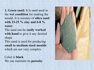
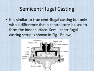
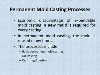
![Chvorinov’s rule
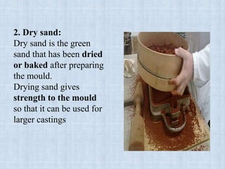
• Total solidification time (ts) = B (V/A) n
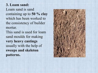
where n = 1.5 to 2.0
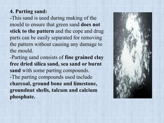
[Where, B = mould constant and is a function of (mould
material, casting material, and condition of casting]
n = 2 and triser = 1.25 tcasting
2 2
riser casting
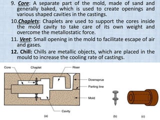
V V
1.25
A A
2
2
V D H / 4
DA DH 2
4
For cylinder of
diameter D
and height H
or](https://image.slidesharecdn.com/lecture2casting-160411082846/85/Lecture-2-casting-full-98-320.jpg)
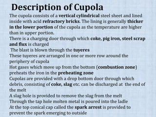
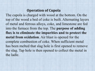

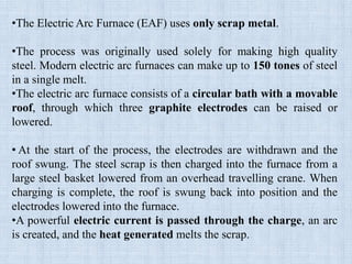
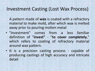
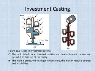

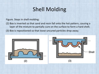
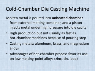

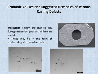
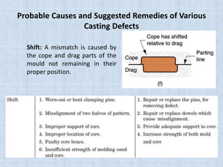
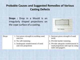
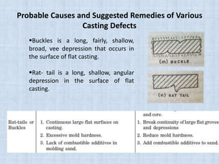
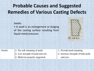

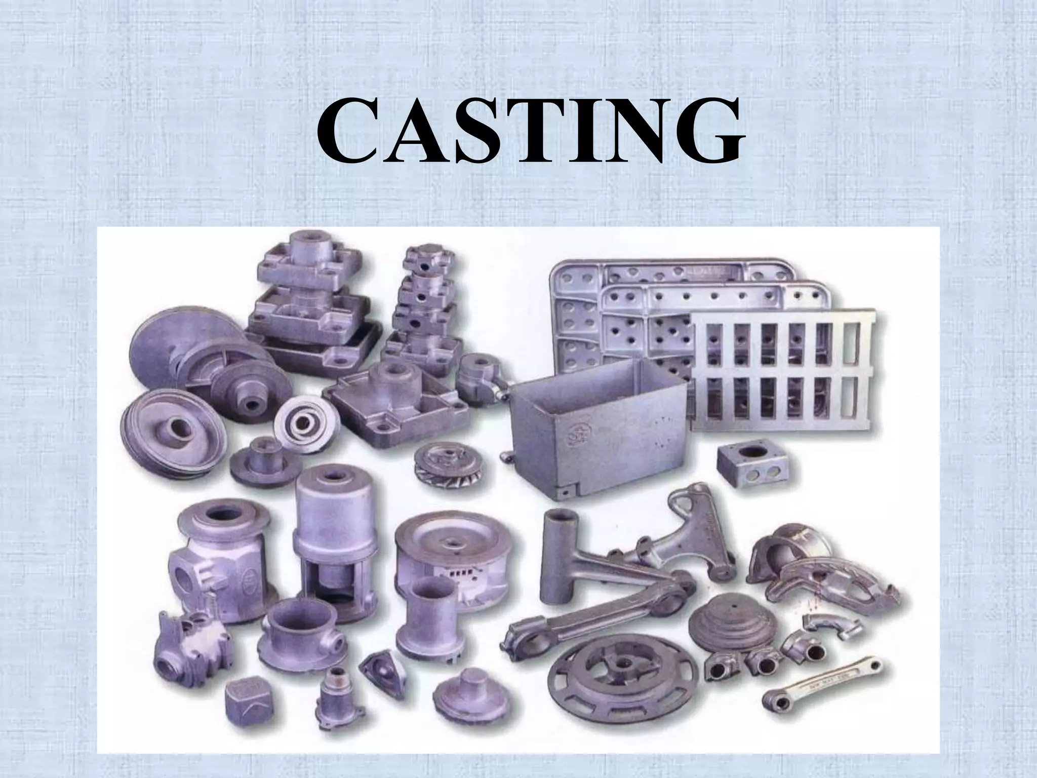
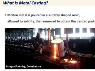
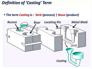
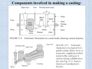
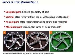
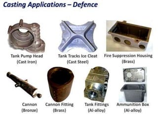
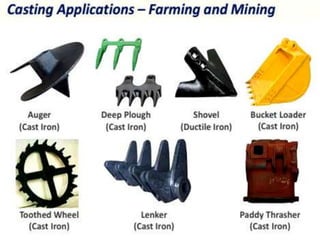
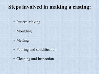
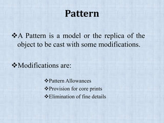
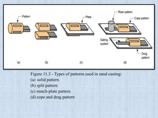
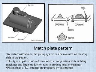
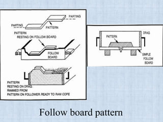
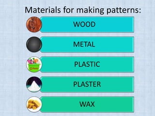
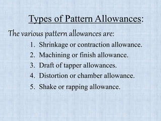
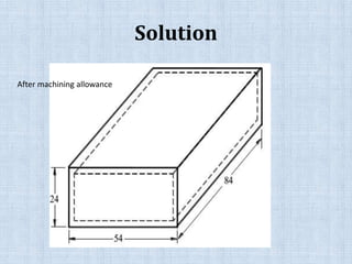
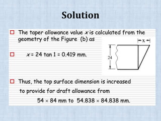
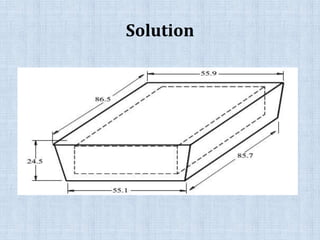
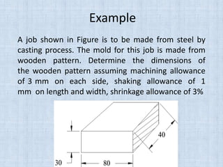
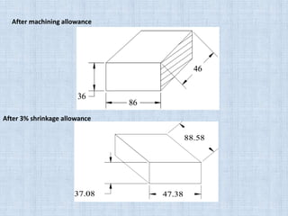
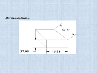
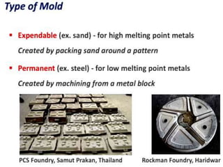
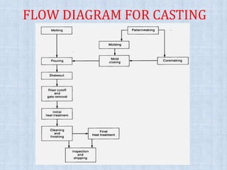
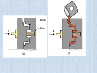
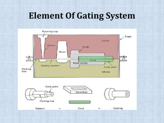
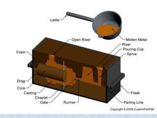
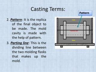
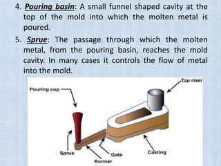
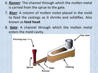
This document provides information on the casting process, including definitions, components, steps, and considerations. Some key points: 1. The casting process involves pouring molten metal into a mold patterned after the part, allowing it to solidify, and removing the part from the mold. Important considerations are metal flow, solidification, and mold material. 2. Components include patterns, molds, cores, and gating systems. Steps are pattern making, molding, melting, pouring, solidification, cleaning, and inspection. 3. Patterns are modified replicas of the object and include allowances for shrinkage, draft, and machining. Common pattern materials are wood, metal, and plastic


