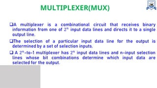
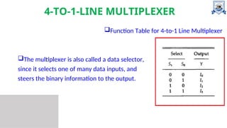
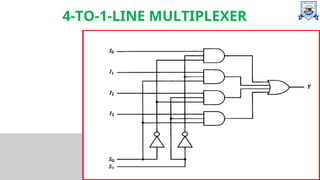
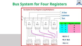
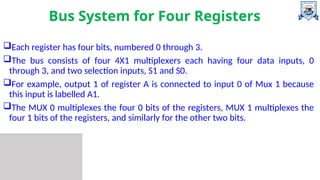
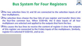
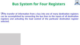
Computer
Organization and
Architecture
BUS SYSTEM USING
MULTIPLEXER
Contents
MULTIPLEXER
BUS SYSTEM USING MULTIPLEXER
MULTIPLEXER(MUX)
4-TO-1-LINE MULTIPLEXER
Function Table for 4-to-1 Line Multiplexer
The multiplexer is also called a data selector,
since it selects one of many data inputs, and
steers the binary information to the output.
4-TO-1-LINE MULTIPLEXER
BUS SYSTEM USING MULTIPLEXER
A typical digital computer has many registers, and paths must be
provided to transfer information from one register to another.
The number of wires will be excessive if separate lines are used between
each register and all other registers in the system.
A more efficient scheme for transferring information between registers in
a multiple-register configuration is a common bus system.
BUS SYSTEM USING MULTIPLEXER
A bus structure consists of a set of common lines, one for each bit of a
register, through which binary information is transferred one at a time.
Control signals determine which register is selected by the bus during
each particular register transfer.
One way of constructing a common bus system is with multiplexers.
The multiplexers select the source register whose binary information is
then placed on the bus.
Bus System for Four Registers
Each register has four bits, numbered 0 through 3.
The bus consists of four 4X1 multiplexers each having four data inputs, 0
through 3, and two selection inputs, S1 and S0.
For example, output 1 of register A is connected to input 0 of Mux 1 because
this input is labelled A1.
The MUX 0 multiplexes the four 0 bits of the registers, MUX 1 multiplexes the
four 1 bits of the registers, and similarly for the other two bits.
Bus System for Four Registers
The two selection lines S1 and S0 are connected to the selection inputs of all
four multiplexers.
The selection lines choose the four bits of one register and transfer them into
the four-line common bus. When S1S0=00, the 0 data inputs of all four
multiplexers are selected and applied to the outputs that form the bus.
This causes the bus lines to receive the content of register A since the outputs
of this register are connected to the 0 data inputs of the multiplexers. Similarly,
register B is selected if S1S0=01, and so on.
Bus System for Four Registers
In general, a bus system will multiplex k registers of n bits each to produce an
n-line common bus.
The number of multiplexers needed to construct the bus is equal to n, the
number of bits in each register.
The size of each multiplexer must be k X 1 since it multiplexes k data lines.
Bus System for Four Registers
The transfer of information from a bus into one of many destination registers
can be accomplished by connecting the bus lines to the inputs of all destination
registers and activating the load control of the particular destination register
selected.
References
 Computer System Architecture - M. Mano , 3rd
Edition.
Thank
You

Bus system using Multiplexer in COA .ppt

  • 1.
  • 2.
  • 3.
  • 4.
    4-TO-1-LINE MULTIPLEXER Function Tablefor 4-to-1 Line Multiplexer The multiplexer is also called a data selector, since it selects one of many data inputs, and steers the binary information to the output.
  • 5.
  • 6.
    BUS SYSTEM USINGMULTIPLEXER A typical digital computer has many registers, and paths must be provided to transfer information from one register to another. The number of wires will be excessive if separate lines are used between each register and all other registers in the system. A more efficient scheme for transferring information between registers in a multiple-register configuration is a common bus system.
  • 7.
    BUS SYSTEM USINGMULTIPLEXER A bus structure consists of a set of common lines, one for each bit of a register, through which binary information is transferred one at a time. Control signals determine which register is selected by the bus during each particular register transfer. One way of constructing a common bus system is with multiplexers. The multiplexers select the source register whose binary information is then placed on the bus.
  • 8.
    Bus System forFour Registers
  • 9.
    Bus System forFour Registers Each register has four bits, numbered 0 through 3. The bus consists of four 4X1 multiplexers each having four data inputs, 0 through 3, and two selection inputs, S1 and S0. For example, output 1 of register A is connected to input 0 of Mux 1 because this input is labelled A1. The MUX 0 multiplexes the four 0 bits of the registers, MUX 1 multiplexes the four 1 bits of the registers, and similarly for the other two bits.
  • 10.
    Bus System forFour Registers The two selection lines S1 and S0 are connected to the selection inputs of all four multiplexers. The selection lines choose the four bits of one register and transfer them into the four-line common bus. When S1S0=00, the 0 data inputs of all four multiplexers are selected and applied to the outputs that form the bus. This causes the bus lines to receive the content of register A since the outputs of this register are connected to the 0 data inputs of the multiplexers. Similarly, register B is selected if S1S0=01, and so on.
  • 11.
    Bus System forFour Registers In general, a bus system will multiplex k registers of n bits each to produce an n-line common bus. The number of multiplexers needed to construct the bus is equal to n, the number of bits in each register. The size of each multiplexer must be k X 1 since it multiplexes k data lines.
  • 12.
    Bus System forFour Registers The transfer of information from a bus into one of many destination registers can be accomplished by connecting the bus lines to the inputs of all destination registers and activating the load control of the particular destination register selected.
  • 13.
    References  Computer SystemArchitecture - M. Mano , 3rd Edition.
  • 14.