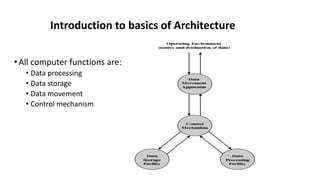
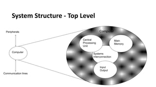
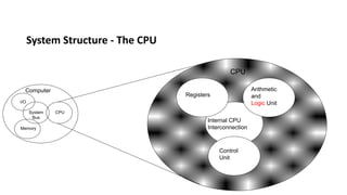
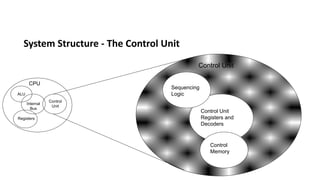
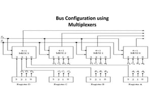
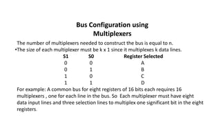
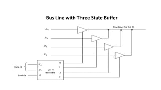
Introduction to basics of Architecture
•All computer functions are:
• Data processing
• Data storage
• Data movement
• Control mechanism
Introduction to basics of Architecture
System Structure - Top Level
Computer
Main
Memory
Input
Output
Systems
Interconnection
Peripherals
Communication lines
Central
Processing
Unit
Computer
System Structure - The CPU
Computer Arithmetic
and
Logic Unit
Control
Unit
Internal CPU
Interconnection
Registers
CPU
I/O
Memory
System
Bus
CPU
System Structure - The Control Unit
CPU
Control
Memory
Control Unit
Registers and
Decoders
Sequencing
Logic
Control
Unit
ALU
Registers
Internal
Bus
Control Unit
Bus Organization
• The CPU communicates with the other components via a bus. A bus is a
set of Wires (multiplexers) that acts as a shared but common data path to
connect multiple subsystems within the system. It consists of multiple
lines, allowing the parallel movement of bits.
• Buses are low cost but very versatile, and they make it easy to connect
new devices to each other and to the system. At any one time, only one
device (be it a register, the ALU, memory, or some other component) may
use the bus. However, this sharing often results in a communications
bottleneck. The speed of the bus is affected by its length as well as by the
number of devices sharing it.
Common Bus configuration System
A more efficient scheme for transferring information between common bus
registers in a multiple-register configuration is a common bus system. A bus
structure consists of a set of common lines, one for each bit of a register,
through which binary information is transferred one at a time. Control
signals determine which register is selected by the bus during each
particular register transfer. Constructing a common bus system
a. Using multiplexers
b. Using three state buffers.
Bus Configuration using
Multiplexers
Bus Configuration using
Multiplexers
The number of multiplexers needed to construct the bus is equal to n.
•The size of each multiplexer must be k x 1 since it multiplexes k data lines.
S1 S0 Register Selected
0 0 A
0 1 B
1 0 C
1 1 D
For example: A common bus for eight registers of 16 bits each requires 16
multiplexers , one for each line in the bus. So Each multiplexer must have eight
data input lines and three selection lines to multiplex one significant bit in the eight
registers.
Bus Configuration using three State Buffer (Gate)
A three-state gate is a digital circuit that exhibits three states.
Two of the states are signals equivalent to logic 1 and 0 as in a
conventional gate. The third state is a high impedance state.
•The high-impedance state behaves like an open circuit, which
means that the output is disconnected and does not have logic
significance.
•Three-state gates may perform any conventional logic, such as
AND or NAND. However, the one most commonly used in the
design of a bus system is the buffer gate.
Three State Buffer
B A B
C=0
B A B
Buffer
Open Circuit
A
A
Construction of Bus by Three State Buffer
The outputs of four buffers are connected together to form a single bus
line. (It must be realized that this type of connection cannot be done
with gates that do not
have three-state outputs.) The control inputs to the buffers determine
which of the four normal inputs will communicate with the bus line.
•No more than one buffer may be in the active state at any given time.
The connected buffers must be controlled so that only one three-state
buffer has access to the bus line while all other buffers are maintained in
a high- impedance state.
•One way to ensure that no more than one control input is active at any
given time is to use a decoder, as shown in the diagram.
Bus Line with Three State Buffer

Computer Components with explanation 1.pdf

  • 1.
    Introduction to basicsof Architecture
  • 2.
    •All computer functionsare: • Data processing • Data storage • Data movement • Control mechanism Introduction to basics of Architecture
  • 3.
    System Structure -Top Level Computer Main Memory Input Output Systems Interconnection Peripherals Communication lines Central Processing Unit Computer
  • 4.
    System Structure -The CPU Computer Arithmetic and Logic Unit Control Unit Internal CPU Interconnection Registers CPU I/O Memory System Bus CPU
  • 5.
    System Structure -The Control Unit CPU Control Memory Control Unit Registers and Decoders Sequencing Logic Control Unit ALU Registers Internal Bus Control Unit
  • 6.
    Bus Organization • TheCPU communicates with the other components via a bus. A bus is a set of Wires (multiplexers) that acts as a shared but common data path to connect multiple subsystems within the system. It consists of multiple lines, allowing the parallel movement of bits. • Buses are low cost but very versatile, and they make it easy to connect new devices to each other and to the system. At any one time, only one device (be it a register, the ALU, memory, or some other component) may use the bus. However, this sharing often results in a communications bottleneck. The speed of the bus is affected by its length as well as by the number of devices sharing it.
  • 7.
    Common Bus configurationSystem A more efficient scheme for transferring information between common bus registers in a multiple-register configuration is a common bus system. A bus structure consists of a set of common lines, one for each bit of a register, through which binary information is transferred one at a time. Control signals determine which register is selected by the bus during each particular register transfer. Constructing a common bus system a. Using multiplexers b. Using three state buffers.
  • 8.
  • 9.
    Bus Configuration using Multiplexers Thenumber of multiplexers needed to construct the bus is equal to n. •The size of each multiplexer must be k x 1 since it multiplexes k data lines. S1 S0 Register Selected 0 0 A 0 1 B 1 0 C 1 1 D For example: A common bus for eight registers of 16 bits each requires 16 multiplexers , one for each line in the bus. So Each multiplexer must have eight data input lines and three selection lines to multiplex one significant bit in the eight registers.
  • 10.
    Bus Configuration usingthree State Buffer (Gate) A three-state gate is a digital circuit that exhibits three states. Two of the states are signals equivalent to logic 1 and 0 as in a conventional gate. The third state is a high impedance state. •The high-impedance state behaves like an open circuit, which means that the output is disconnected and does not have logic significance. •Three-state gates may perform any conventional logic, such as AND or NAND. However, the one most commonly used in the design of a bus system is the buffer gate.
  • 11.
    Three State Buffer BA B C=0 B A B Buffer Open Circuit A A
  • 12.
    Construction of Busby Three State Buffer The outputs of four buffers are connected together to form a single bus line. (It must be realized that this type of connection cannot be done with gates that do not have three-state outputs.) The control inputs to the buffers determine which of the four normal inputs will communicate with the bus line. •No more than one buffer may be in the active state at any given time. The connected buffers must be controlled so that only one three-state buffer has access to the bus line while all other buffers are maintained in a high- impedance state. •One way to ensure that no more than one control input is active at any given time is to use a decoder, as shown in the diagram.
  • 13.
    Bus Line withThree State Buffer