Download to read offline

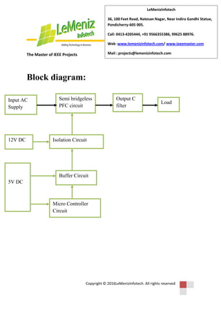

The document discusses a new bumpless controller design for power factor correction circuits aimed at improving energy efficiency and power factor compliance with standards like Energy Star. It highlights the benefits of using a semi-bridgeless topology, which offers high efficiency and lowers ripple content, making it suitable for energy storage and renewable energy applications. The proposed system's performance is enhanced by testing the bumpless controllers through simulations and hardware implementation.