This document discusses a power factor correction (PFC) strategy for a two-leg inverter fed brushless DC motor (BLDCM) drive using a Cuk DC-DC converter. The proposed method improves efficiency and reduces torque ripple while maintaining nearly unity power factor during operation. Detailed modeling and simulation results are provided to support the effectiveness of the system under varying conditions.
![International Journal of Power Electronics and Drive System (IJPEDS)
Vol. 6, No. 2, June 2015, pp. 196~204
ISSN: 2088-8694 196
Journal homepage: http://iaesjournal.com/online/index.php/IJPEDS
Power Factor Correction in Two Leg Inverter Fed BLDC Drive
Using Cuk Dc-Dc Converter
A. Purna Chandra Rao*, Y.P. Obulesh**, Ch. Sai Babu***
* Prasad V. Potluri Siddhartha Institute of Technology, Vijayawada, Andhra Pradesh, India
** KL University, Guntur, Andhra Pradesh, India
*** Jawaharlal Nehru Technological University Kakinada, Kakinada, Andhra Pradesh, India
Article Info ABSTRACT
Article history:
Received Feb 26, 2015
Revised Apr 29, 2015
Accepted May 12, 2015
Earlier for variable speed application conventional motors were used, but
these motors have poor characteristics. These drawbacks were overcome by
brushless Dc motor drive. Now days in most of the applications such as
industrial, domestic, aerospace, defense, medical and traction etc, brushless
DC motor (BLDCM) is popular for its high efficiency, high torque to weight
ratio, small size, and high reliability, ease of control and low maintenance
etc. BLDC motor is a electronic commutator driven drive i.e. it uses a three-
phase voltage source inverter for its operation, electronic devices means there
is a problem of poor power quality, more torque ripple and speed
fluctuations. This paper deals with the CUK converter two leg inverter fed
BLDCM drive in closed loop operation. The proposed control strategy on
CUK converter two leg inverter fed BLDCM drive with split DC source is
modeled and implemented using MATLAB/Simulink. The proposed method
improves the efficiency of the drive system with Power factor correction
feature in wide range of the speed control, less torque ripple and smooth
speed control.
Keyword:
BLDC motor
CUK converter
PFC
Power quality
Torque ripple
Copyright © 2015 Institute of Advanced Engineering and Science.
All rights reserved.
Corresponding Author:
A. Purna Chandra Rao,
Department of Electrical and Electronics Engineering,
Prasad V. Potluri Siddhartha Institute of Technology,
Vijayawada, Andhra Pradesh, India
Email: alapati.purna@yahoo.com
1. INTRODUCTION
Conventional motor like induction motor and DC motors are most popular electric drives in 20th
century. Recently development in power electronics technology and control technology, it application to
electrical drive system has increased. The main advantages of induction motor are simple construction,
simple maintenance, no slip rings and moderate reliability. The drawbacks are small air gap cracking of rotor
bars due to hot spots and lower efficiency and power factor.
The use of permanent magnets in construction of electric machine has following benefits there is no
excitation losses, high torque to weight ratio, better dynamic performance, simple construction and less
maintenance therefore permanent magnet motors has becomes an attractive option. The development in
power electronics technology and control technology and drooping of cost in power electronics devices make
possible of operating the motor over a wide speed range and maintaining good efficiency. A 3% increase in
motor efficiency can save 2% of energy used [1]
In PMBLDC motor only two phase winding conduct the current and this current in the shape of
square or trapezoidal which produce a rotating magnetic field due to this loss are reduced. Another advantage
of brushless motor is that power loss occur in stator only, because of this heat transfer condition is good.
Considerable improvement in the dynamics is achieved because the air gap flux density high, rotor has low
inertia, thus the volume of the motor is reduced by more than 40% [2]. Now days due to the simplicity in](https://image.slidesharecdn.com/0229apr1526feb5826ijpedspfc2leg-171215012051/75/Power-Factor-Correction-in-Two-Leg-Inverter-Fed-BLDC-Drive-Using-Cuk-Dc-Dc-Converter-1-2048.jpg)
![ ISSN: 2088-8694
IJPEDS Vol. 6, No. 2, June 2015 : 196 – 204
197
their control, Permanent-magnet brushless dc motors are more widely used in high-performance applications
and, the production of ripple-free torque is of primary concern in these applications.
BLDC motor is a electronic commutator driven drive i.e. it uses a three-phase voltage source
inverter for its operation, electronic devices means there is a problem of poor power quality, more torque
ripple and speed fluctuations. For driving the BLDC motor we use single phase ac supply which is convert to
DC with diode bridge rectifier and it output is given to capacitor i.e. DC link capacitor. Due to this DC link
capacitor charging and discharging; on AC supply side current is in pulsating form, this cause the power
quality problem. Due to many advantages over conventional drives its popularity and its usage is increased
and on utility side it cause more severe PQ problem. Research Work is going on to develop an electrical drive
system with inherent power factor correction converter (PFC). PFC will force the drive system to draw
sinusoidal current from AC supply mains and maintain nearly unity power factor. A PFC converter means an
extra cost and complexity which is not acceptable. There are so many PFC converter topologies are available
in which DC-DC converter topology is more popular due to low cost and less complexity. Buck, boost, buck
boost, SEPIC are the examples for DC-DC converters topology. In air-conditioners applications, a BLDCM
with boost PFC converter [3] and PMSM with improved power quality converter [4] have been reported for
power quality improvement, results in improvement in performance such as improved efficiency, reduction
of harmonics on AC supply side, noise reduction etc .
This paper deals with the application of cuk converter as PFC to feed two leg inverter fed BLDCM
with split DC supply, results in improvement in performance such as improved efficiency, reduction of
harmonics on AC supply side, noise reduction, nearly unity power factor at ac supply side, less torque ripple
and smooth sped control.
Figure 1. Schematic Diagram of Proposed CUK PFC two leg inverter fed BLDCM with split DC supply
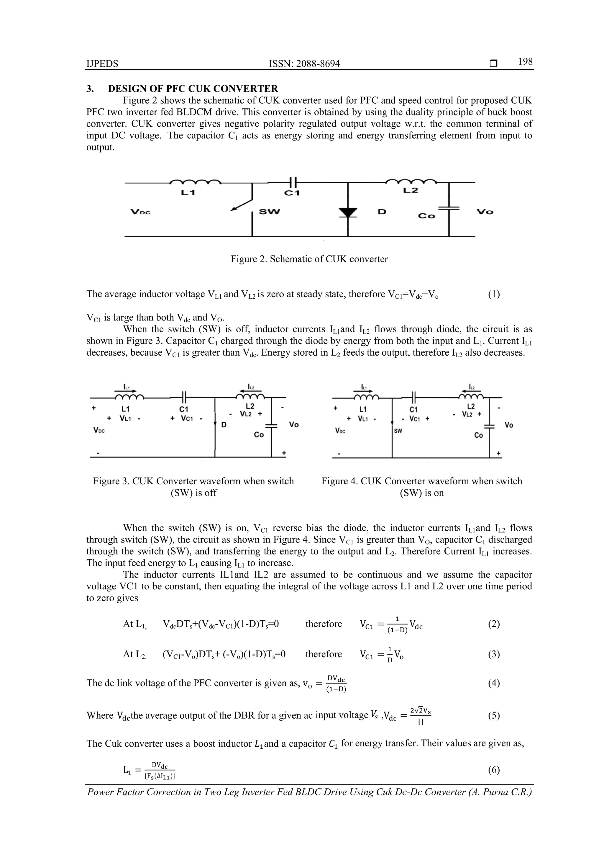
2. OPERATION OF CUK PFC TWO LEG INVERTER FED BLDCM DRIVE
Figure 1 shows the schematic diagram of proposed CUK PFC two inverter fed BLDCM with split
DC supply for speed control as well as PFC in vide range of input AC voltage. It consist of two schemes one
is Power factor correction control scheme which uses a current multiplier approach concept with a current
control loop inside and second one is the speed control loop for continuous-conduction-mode operation of the
converter. First reference DC link voltage is compared with the actual DC link voltage which generates the
DC link voltage error signal (Vdc_error), which is processed through a PI controller to generate control
signal (Ic). This control signal multiplied with a unit template of input ac voltage to get reference DC link
current (Idc_ref). This reference DC link current (Idc_ref) is compared with dc link current (IDC) which is
sensed after diode bridge rectifier. The resultant DC current error (IDC_err) is amplified and compared with
a saw tooth carrier wave of fixed frequency (Fs) to generate the pulse width modulation (PWM) pulse for the
Cuk convertor. Its duty ratio (D) at a switching frequency (Fs) controls the dc link voltage at the desired
value. For speed control reference speed is compared with actual speed of the motor which gives speed error
(Nerr) which is processed through PI controller, which give reference current signal (Iref), this reference
current signal is multiply with hall sensor current position information, which generate the reference stator
current signal (Ia_ref). This reference stator current signal (Ia_ref) processed with hysteresis controller to
generate the firing pulse for voltage source inverter.](https://image.slidesharecdn.com/0229apr1526feb5826ijpedspfc2leg-171215012051/75/Power-Factor-Correction-in-Two-Leg-Inverter-Fed-BLDC-Drive-Using-Cuk-Dc-Dc-Converter-2-2048.jpg)
![ ISSN: 2088-8694
IJPEDS Vol. 6, No. 2, June 2015 : 196 – 204
199
C
∆
(7)
Where ∆IL1 is a specified inductor current ripple, ∆VC1 is a specified voltage ripple in the
intermediate capacitor (C1), and Idc is the current drawn by the BLDCM from the dc link. A ripple filter is
designed for ripple-free voltage at the dc link of the Cuk converter. The inductance (L2) of the ripple filter
restricts the inductor peak-to-peak ripple current (∆IL2) within a specified value for the given switching
frequency (Fs), whereas the capacitance (Co) is calculator for the allowed ripple in the dc link voltage
(∆VCd). The values of the ripple filter inductor and capacitor are given as,
L
..
∆ (8)
ɷ∆
(9)
The advantage of CUK converter circuit is that both the input current and the current feeding the
output are reasonable ripple free, therefore it is possible to simultaneously eliminate the ripple in both the
inductor currents completely, leading to lower external filtering requirements and the disadvantage is the
requirement of a capacitor C1 with large ripple current carrying capability.
4. MODELING OF PROPOSED PFC CONVERTER BASED PMBLDCM DRIVE
The PFC cuk two leg inverter fed BLDCM drive with two DC source are the main parts of the
proposed drive system, which are modeled by mathematical equations and a combination of these equations
represents the complete model of the proposed drive system. The PFC converters consist of DBR, cuk
converter and ripple filter. Voltage controller, reference current generator, PWM controller, speed controller,
a reference current generator, a PWM current controller and a PMBLDC motor are used for complete
representation of cuk fed BLDCM drive system.
PFC Converter
The PFC converter block consists of voltage controller, PWM controller and a reference current
generator.
Voltage Controller
The proportional integral (PI) controller is used to control the DC link voltage.
DC voltage error Vdc_e(k) at kth is calculated as V _ k V∗
k V k
V∗
k is reference DC link voltage and V k is sensed DC link voltage at kth instant
This DC voltage error is processed through the Proportional integral voltage controller to get desired control
signal Iref_dc(k) at kth instant is given as,
Iref_dc(k) = I(k-1) + Kpvc[Ve(k) – Ve(k-1)] + KivcVe(k) (10)
Where Kpvc and Kicv are the proportional and integral gains of the voltage controller
Reference Current Generator
The reference inductor current,I∗
, of the Cuk converter is given as,
I∗
I k u (11)
Where uvi is the unit template of the input AC mains voltage calculated as,
u ;V |V | ; Vi= Vin sin ωt (12)
where ω is frequency in rad/s at input AC mains.](https://image.slidesharecdn.com/0229apr1526feb5826ijpedspfc2leg-171215012051/75/Power-Factor-Correction-in-Two-Leg-Inverter-Fed-BLDC-Drive-Using-Cuk-Dc-Dc-Converter-4-2048.jpg)
![IJPEDS ISSN: 2088-8694
Power Factor Correction in Two Leg Inverter Fed BLDC Drive Using Cuk Dc-Dc Converter (A. Purna C.R.)
200
PWM Controller
The reference Cuk converter current is compared with its sensed current to generate the current error
∆i I∗
I . This current error is amplified by gain Pdc and compared with carrier waveform Qd(t). The
switching signals for the IGBT of the PFC converter are generated by comparing this amplified current error
with saw-tooth carrier waveform of 2 kHz.
If Pdc ∆idc > Qd (t) then Scuk = 1 (13)
If Pdc ∆idc ≤ Qd (t) then Scuk = 0 (14)
where Scuk is the switching function of the switch used in Cuk converter representing, “on” position
with Scuk = 1 and its “off” position with Scuk = 0.
PMBLDCM Drive
The modelling of a speed controller is quite important as the performance of the system depends on
this controller. If at kth instant of time, ω∗
k is reference speed, ωr(k) is rotor speed then the speed error
ωe(k) can be calculated as,
ω k ω∗
k ω k (15)
This speed error is processed through a speed controller to get desired control signal.
Speed Controller
The output of the PI controller at kth instant T (k) is given as,
T (k) = T (k-1) + Kps[ωe(k) – ωe(k-1)] + Kis ωe(k) (16)
Where Kps and Kis are the proportional and integral gains of the speed controller.
Reference Winding Currents
The amplitude of stator winding current is as,
I∗
_
(17)
Where Kb_emf is the back emf constant of the BLDCM.
The reference phase currents of the motor winding are denoted by for phases i∗
, i∗
for phases a, b
respectively. For duration of 0-60º the reference currents can be given as i∗
1, and i∗
1, Similarly, the
reference winding currents during other 60º duration are generated in rectangular 120º block form in phase
with trapezoidal voltage of respective phases. These reference currents are compared with sensed phase
currents to generate the current errors ∆i i∗
i , ∆i i∗
i , for three phases of the motor.
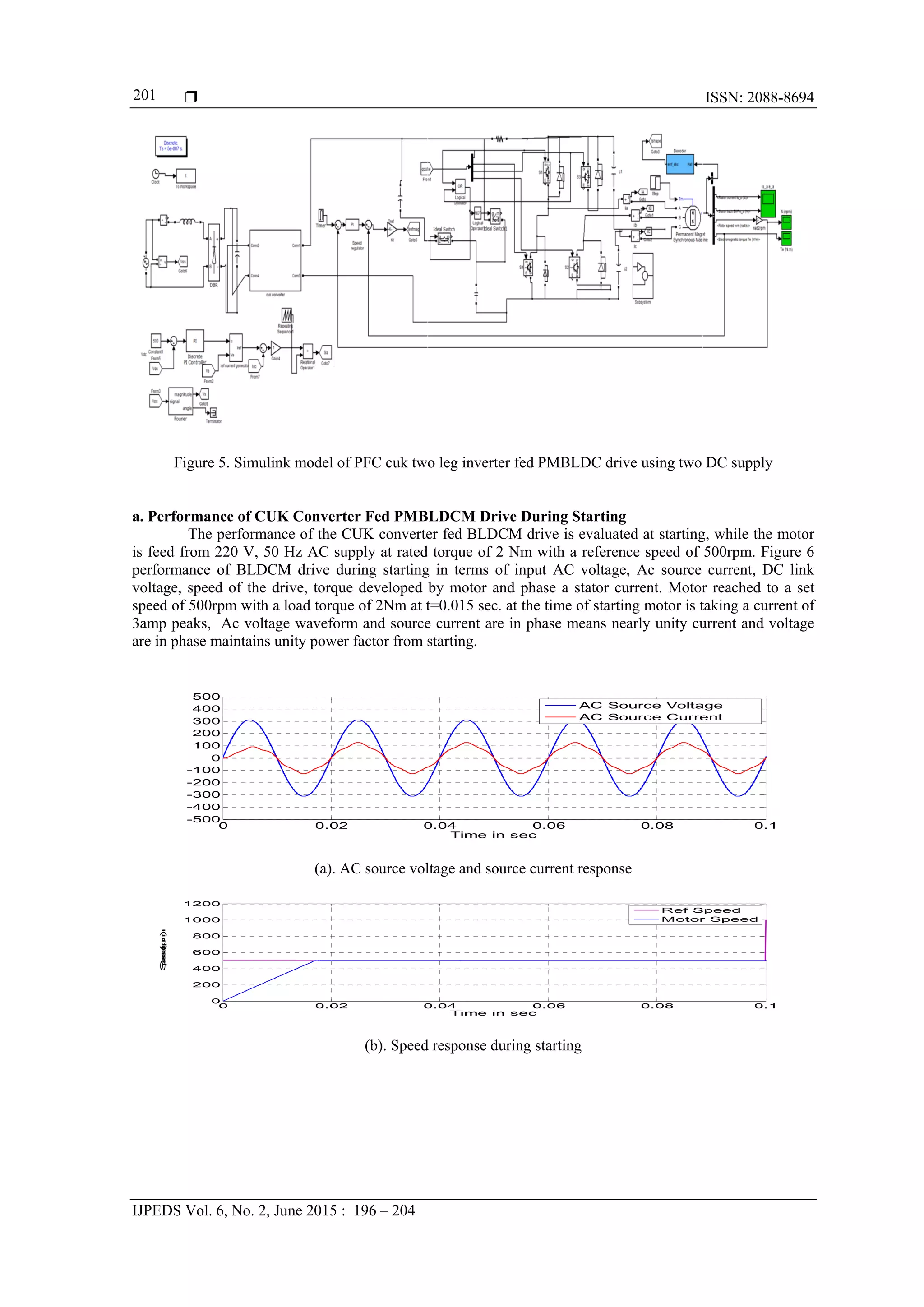
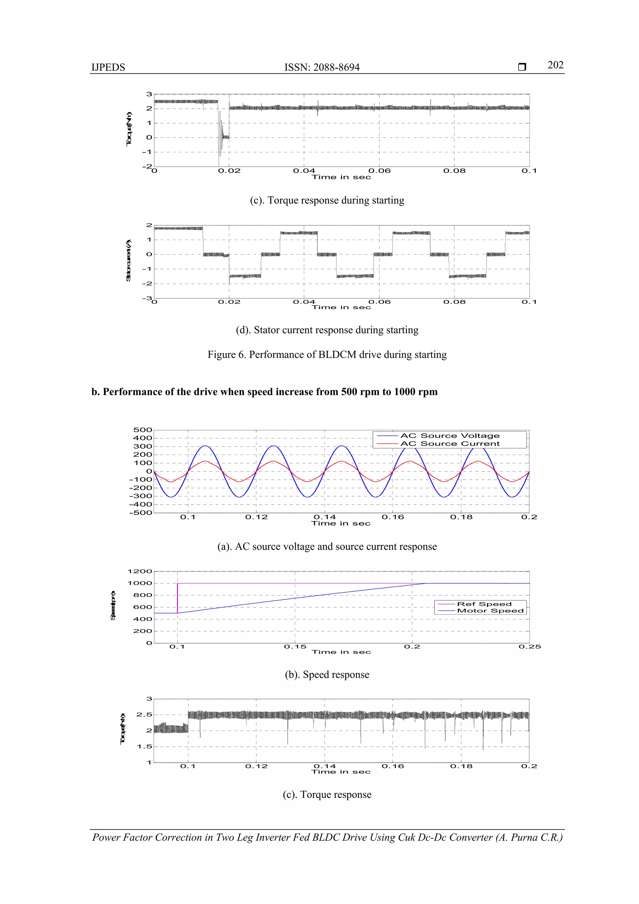
5. RESULTS AND ANALYSIS
Simulation model was developed using MATLAB/ SIMULINK software to test and validate the
performance of PFC cuk two leg inverter fed BLDCM drive using split DC supply. Figure 5 Shows the
Simulink block diagram of PFC cuk two leg inverter fed PMBLDC drive using split DC supply. The
performance of the PFC cuk two leg inverter fed BLDCM drive using split DC supply is analyzed on the
basis of various factor such as mechanical parameters, electrical parameters of the BLDC motor and the front
end CUK converter i.e. the speed, stator current and electromagnetic torque, DC link voltage, the cuk
inductor current, the voltage across the bulk capacitor, which shows satisfactory performance of the CUK
converter fed BLDCM drive. Parameters such as the power factor, the Total Harmonic Distortion, supply
current and supply voltage determine the performance of the drive in terms of power quality. The
performance of the drive is simulated for constant rated torque (2 Nm) at rated speed of 1000 rpm, with an
input AC voltage of 220V, 50 Hz supply.](https://image.slidesharecdn.com/0229apr1526feb5826ijpedspfc2leg-171215012051/75/Power-Factor-Correction-in-Two-Leg-Inverter-Fed-BLDC-Drive-Using-Cuk-Dc-Dc-Converter-5-2048.jpg)
![IJPEDS ISSN: 2088-8694
Power Factor Correction in Two Leg Inverter Fed BLDC Drive Using Cuk Dc-Dc Converter (A. Purna C.R.)
204
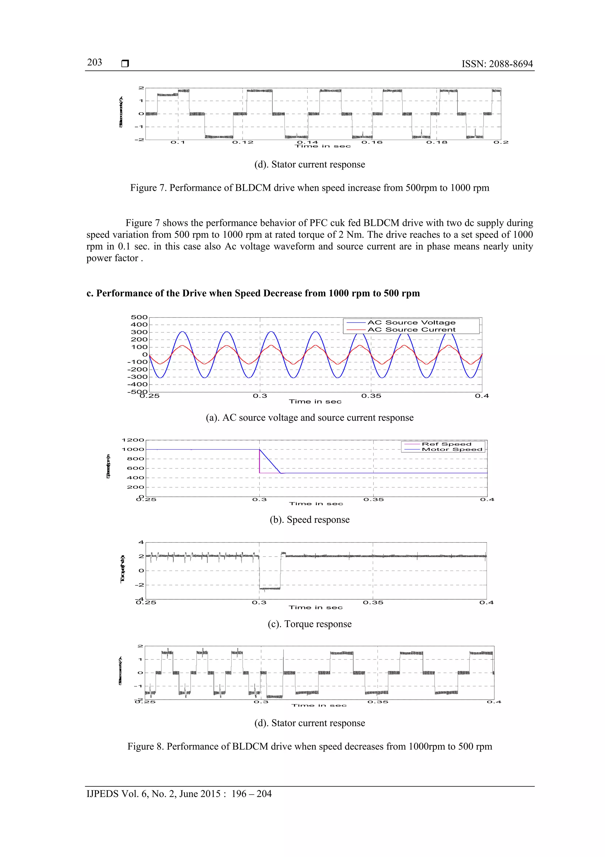
Figure 8 shows the performance behavior of PFC cuk two leg inverter fed BLDCM drive with two
dc supply during speed variation from 1000 rpm to 500 rpm at rated torque of 2 Nm. The drive reaches to a
set speed of 500 rpm in 0.05 sec. in this case also Ac voltage waveform and source current are in phase
means nearly unity power factor .
d. Performance under Steady State Condition
AC source current and harmonic spectra of PFC cuk two leg inverter fed BLDCM drive with two dc
supply during steady-state condition at rated torque, speed at 500rpm and 1000rpm is found. A THD of 7% is
observed at a speed of 500 rpm and when the speed is 1000rpm THD is 3.5%. Moreover, an improved
performance of the PMBLDCM drive is observed in terms of reduced ripples in torque, current and speed
during steady state conditions.
6. CONCLUSION
Brushless DC motor (BLDCM) is popular for its high efficiency, high torque to weight ratio, small
size, and high reliability, ease of control and low maintenance etc and replacing the conventional motor in so
many applications. In this paper a PFC cuk based two leg inverter PMBLDCM drive with split DC source is
analyzed and validated for applications. A smooth speed control is observed while controlling the dc link
voltage. The performance of the drive is good and satisfactory in the wide range of input ac voltage and
maintaining good power factor with less torque ripple, smooth speed control of the PMBLDCM drive. The
THD of ac mains current is observed well below 7% in most of the cases and satisfies the international
standards.
REFERENCES
[1] Mc Naught C IEE Review 3, pp 89-91, 1993
[2] Cremer R. Current status of rare earth permanent magnet. Int conf on Maglev and liner drives, Germany, 1998, pp.
391-398
[3] Singh, B. Singh, B.P. and Kumar, M. (2003). PFC converter fed PMBLDC motor drive for air conditioning.
Institution of Engineers (India) Journal-EL, 84, 22-27.
[4] Singh, B. Murthy, S.S. Singh, B.P. and Kumar, M. (2003). Improved power quality converter fed permanent
magnet AC motor for air conditioning. Electric Power System Research, 65(3), 239-245.
[5] García, O. Cobos, J.A. Prieto, R. Alou, P. and Uceda, J. (2003). Single phase power factor correction: A survey.
IEEE Trans. Power on Electronics, 18(3), 749-755.
[6] C.B. Jacobina, M.B. de Rossiter Correa, E.R.C. da Silva, and A.M.N. Lima, “A General PWM Strategy for Four-
Switch Three-Phase Inverters”, IEEE Trans. Energy Conversion, vol. 21, no. 4, pp. 832-838, Dec. 2006.](https://image.slidesharecdn.com/0229apr1526feb5826ijpedspfc2leg-171215012051/75/Power-Factor-Correction-in-Two-Leg-Inverter-Fed-BLDC-Drive-Using-Cuk-Dc-Dc-Converter-9-2048.jpg)


![6.[36 45]seven level modified cascaded inverter for induction motor drive app...](https://cdn.slidesharecdn.com/ss_thumbnails/6-36-45sevenlevelmodifiedcascadedinverterforinductionmotordriveapplications-111118181646-phpapp02-thumbnail.jpg?width=640&height=640&fit=bounds)


