This document provides an overview of the building services systems at the Malaysia International Trade and Exhibition Centre (MITEC). It includes 3 sections that summarize the key fire protection, air conditioning, and mechanical transportation systems. The fire protection system utilizes sprinklers, hydrants, detectors, and alarms to help control fires. The air conditioning system includes chillers, cooling towers, air handling units, and fan coil units to provide temperature control. The mechanical transportation section describes the escalators and elevators that facilitate vertical transportation within the building.

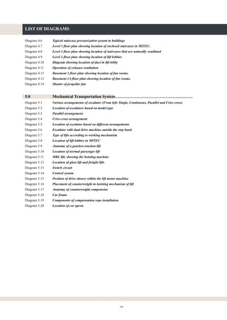

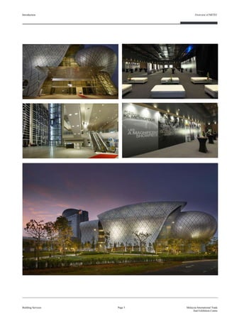
![2.1.2.1.1 Jockey Pump
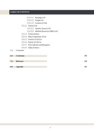
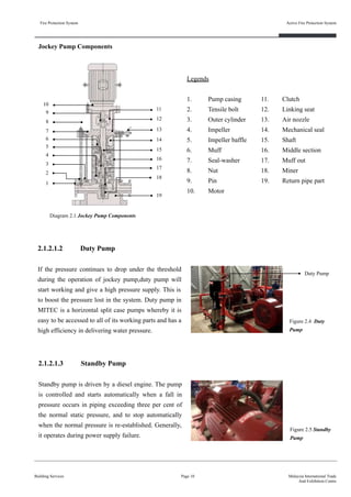
Jockey pump, also known as a pressure-maintenance pump, is a
relatively small device that works together with the fire pump. It
is designed to keep the pressure in the system elevated to a
specific level when the system is not in use, so that the fire pump
doesn’t have to run all the time. This prevents the sprinklers
from going off unnecessarily. Moreover, since pipes are
susceptible to leakage over time, the water pressure inside them
tends to go down. As soon as the jockey pump senses this, it fills
them back up to normal pressure. Also, it can also help prevent
the system from damage when a fire happens and pressurized
water rushes into the pipes by regulating the pressure. It is
powered by electric supply and is connected directly to the fire
sprinkler water tank.
Fire Protection System
Building Services
Active Fire Protection System
Page 9 Malaysia International Trade
And Exhibition Centre
Jockey Pump
Duty Pump
Standby Pump
Common Suction
Pipe
Common
Discharge Pipe
Figure 2.1 An overview of fire pump system and sprinkler tank
Figure 2.3 EBSRAY Jockey Pump
Figure 2.2 Fire sprinkler tank and wet
riser-hose reel tank
UBBL 1984
Part VIII: Fire Alarms, Fire Detection, Fire Extinguishment and Fire Fighting Access
[ Clause 247 ] Water Storage
(1) Water storage capacity and water flow rate for fire fighting systems and installations shall be
provided in accordance with the scale as set out in the Tenth Schedule to these By-laws.
(2) Main water storage tanks within the building, other than for hose reel systems, shall be
located at ground, first or second basement levels, with fire brigade pumping inlet
connections accessible to fire appliances.
(Uniform Building By-Law, 2006, pp. 87) (Original work published in 1984)](https://image.slidesharecdn.com/finalisedb-190727174357/85/MITEC-Building-Service-System-22-320.jpg)
![Fire Protection System
Building Services
Active Fire Protection System
Page 11 Malaysia International Trade
And Exhibition Centre
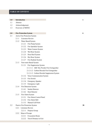
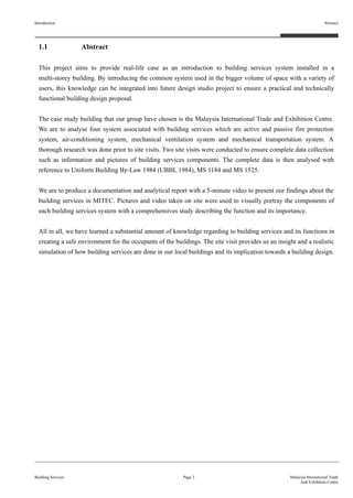
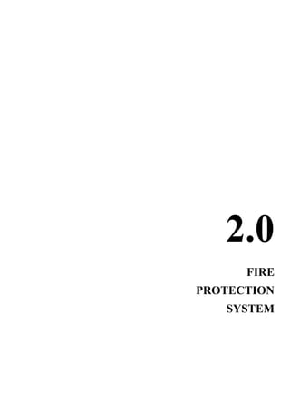
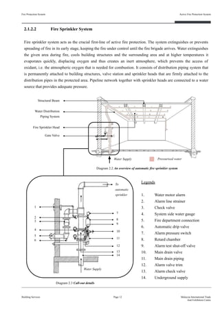
2.1.2.1.4 Pumpset Pressure Indicator
Standby pump is driven by a diesel engine. The pump
is controlled and starts automatically when a fall in
pressure occurs in piping exceeding three per cent of
the normal static pressure, and to stop automatically
when the normal pressure is re-established. Generally,
it operates during power supply failure.
Figure 2.6 Pumpset
Pressure Indicator
2.1.2.1.5 Fire Pump Controller
The fire pump controller is designed to monitor the
operation status and in the case of fire, the controller
will receive a signal from the pressure switch and start
the fire pump. The fire switch in the controller is
passive, requiring no manual operation by the owner.
Water pressure does it all. When the pressure drops,
the normally open contacts close, completing the
electrical circuit and activating the pump.
Figure 2.7 Fire
Pump Controller
UBBL 1984
Part VIII: Fire Alarms, Fire Detection, Fire Extinguishment and Fire Fighting Access
[ Clause 226 ] Automatic System for Hazardous Occupancy
Where hazardous processes, storage or occupancy are of such character as to require automatic
sprinklers or other automatic extinguish fires in the hazardous materials stored or handled or for the
safety of the occupants.
Summary (Fire Pump) :
The water storage tank for both wet riser system and fire sprinkler system meets the UBBL 1984 requirement
listed under Clause 247, (2). The tanks are located on the fire appliance access level for the ease of monitoring.
The automated system including fire pump system, fire sprinkler system and water cannon system meets the
UBBL 1984 requirement listed under Clause 226.
(Uniform Building By-Law, 2006, pp. 82) (Original work published in 1984)](https://image.slidesharecdn.com/finalisedb-190727174357/85/MITEC-Building-Service-System-24-320.jpg)
![Fire Protection System
Building Services
Active Fire Protection System
Page 16 Malaysia International Trade
And Exhibition Centre
UBBL 1984
Part VIII: Fire Alarms, Fire Detection, Fire Extinguishment and Fire Fighting Access
[ Clause 228 ] Sprinkler Valves
(1) Sprinkler valves shall be located in a safe and enclosed position on the exterior wall and
shall be readily accessible to the Fire Authority
(2) All sprinkler system shall be electricity connected to the nearest fire station to provide
immediate and automatic relay of the alarm when activated.
Summary (Fire Sprinkler System) :
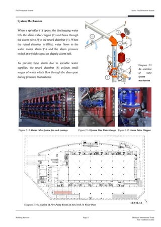
The fire sprinkler system in MITEC meets the UBBL 1984 requirements listed under clause 228, (1) and (2). In
Figure 2.13, the sprinkler alarm valve system is placed along the exterior wall of the fire pump room located at
ground floor. This allow ease of monitoring during the event of fire even without access into the fire pump room.
Also, it is connected to the fire alarm system which is directly linked to the nearest fire station through the fire
control panel.
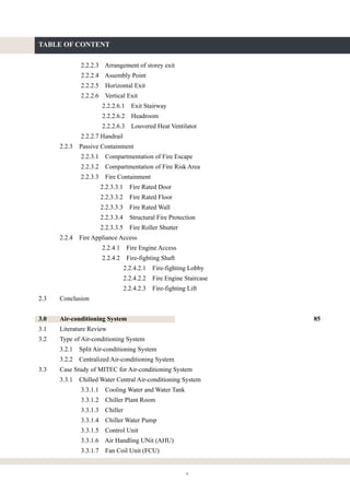
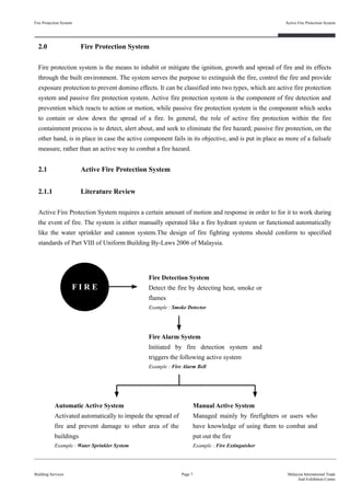
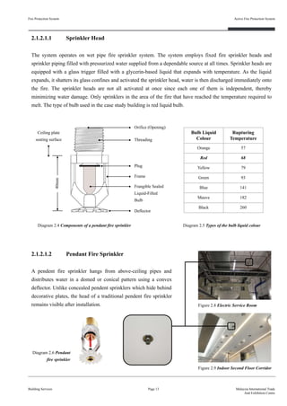
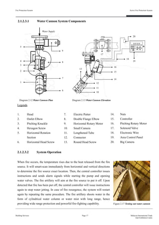
2.1.2.3 Water Cannon System
There are 12 water cannons located at level 3 in the largest exhibition
pillar-less hall. The water cannon system employed in MITEC is an
automatic tracking technology with mechanized positioning fire
artillery, combining the infrared sensor technology. The signal
processing technology, communication control technology, computer
technology and mechanical driven technology work together effectively.
It is exceptionally suitable for tall and big space like the pillar-less hall. Figure 2.16 Water Cannon System
Diagram 2.11 Location of Pillar-less Exhibition Hall where the water cannon system is located
(Uniform Building By-Law, 2006, pp. 82) (Original work published in 1984)
SECTION B-B’](https://image.slidesharecdn.com/finalisedb-190727174357/85/MITEC-Building-Service-System-29-320.jpg)
![Fire Protection System
Building Services
Active Fire Protection System
Page 18 Malaysia International Trade
And Exhibition Centre
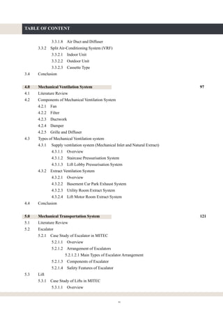
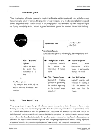
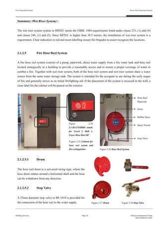
2.1.2.4 Wet Riser System
MITEC has a height of 63 metres above the fire appliance access level therefore wet riser system is installed to
supply pressurized water within buildings for firefighting purposes. The wet rise system in MITEC consists of a
wet riser main, a wet riser landing valve and a hose cradle. Some of the system are being recessed in the wall
located in a cabinet clearly labelled ‘Sesalur Basah’ on a red panel, which means ‘wet riser’ when being direct
translated into English language.
UBBL 1984
Part VIII: Fire Alarms, Fire Detection, Fire Extinguishment and Fire Fighting Access
[ Clause 231 ] Installation and testing of wet rising system
(1) Wet rising systems shall be provided in every building in which the topmost floor is more
than 30.5 metres above fire appliance access level.
[ Clause 248 ] Markings on wet riser, etc.
(1) Wet riser, dry riser, sprinkler and other fire installation pipes and fittings shall be painted
red.
(2) All cabinets and areas recessed in walls for location of fire installations and extinguishers
shall be clearly identified to the satisfaction of the Fire Authority or otherwise clearly
identified.
Figure 2.18 Wet Riser System
Wet Riser
Main
Wet Riser
Landing Valve
Canvas Hose
Hose Cradle
Figure 2.19 Wet riser system that located in the wall
(Uniform Building By-Law, 2006, pp. 84, 87) (Original work published in 1984)](https://image.slidesharecdn.com/finalisedb-190727174357/85/MITEC-Building-Service-System-31-320.jpg)
![Fire Protection System
Building Services
Active Fire Protection System
Page 19 Malaysia International Trade
And Exhibition Centre
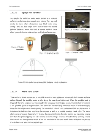
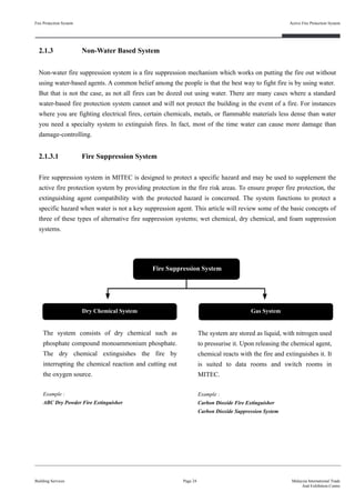
2.1.2.4.2 Wet Riser Landing Valve
Landing valves which are 65mm in diameter, connecting directly to
the wet riser main, serve as the main water supply to fire department
to the upper floors in MITEC whereas fire hydrants serve as the
water source on the ground level. It functions as a water tab whereby
it is to connect the canvas hose to access to the water source on the
upper levels for fire-fighting. The valves are equipped with a
coupling adapter which is directly screwed to the outlet and
stoppered with a cap.
2.1.2.4.1 Wet Riser Main and Air Vent
Wet fire mains are 150mm in diameter and are installed owing to the
pressures required to provide adequate fire-fighting water supplies at
the landing valves at upper floors and also to ensure that water is
immediately available at all floor levels. The provision of a built-in
water distribution system means that firefighters do not need to
create their own distribution system in order to fight a fire and
avoids the breaching of fire compartments by running hose lines
between them.
2.1.2.4.3 Canvas Hose and Hose Cradle
Hose Cradle and Canvas Hose of brand ‘Proflex’ is used in MITEC.
The canvas hose has a length of 30 metres and 65mm in diameter. It
is connected to a faucet and placed on a hose cradle nearby the
landing valve. The hose has no all-time water supply like hose reel
system.
Figure 2.20 Wet riser main
Outlet Coupling Adapter
Figure 2.22 Landing Valves on the top floor
UBBL 1984
Part VIII: Fire Alarms, Fire Detection, Fire Extinguishment and Fire Fighting Access
[ Clause 231 ] Installation and testing of wet rising system
(4) Each wet risers outlet shall comprise standard 63.5 millimeters instantaneous coupling fitted
with a hose of not less than 38.1 millimeters diameter equipped with an approved typed
cradle and a variable fog nozzle.
Figure 2.23 Canvas hose placed on the cradle
Figure 2.21 Air Vent
(Uniform Building By-Law, 2006, pp. 84) (Original work published in 1984)](https://image.slidesharecdn.com/finalisedb-190727174357/85/MITEC-Building-Service-System-32-320.jpg)
![Fire Protection System
Building Services
Active Fire Protection System
Page 21 Malaysia International Trade
And Exhibition Centre
2.1.2.5.5 System Operation
The system is manually operated and activated by opening the stop valve, enabling the water to flow into the
hose that is 30 meters long. The system pressure loss will activate the pump, ensuring adequate water flow and
pressure to provide a water jet of a minimum of 10 meter from the nozzle (0.33L of water per second). The
nozzle attached to the hose enables the operator to control the direction and flow of water to the fire.
Turn water on to the hose reel
by operating the control valve
and remove the nozzle from its
bracket.
Direct the water at the base of
the flames and extinguish the
fire by using a sweeping
action.
Proceed to a safe distance
from the fire and turn the
water on by operating the
nozzle.
UBBL 1984
Part VIII: Fire Alarms, Fire Detection, Fire Extinguishment and Fire Fighting Access
[ Clause 231 ] Installation and testing of wet rising system
(2) A hose connection shall be provided in each fire fighting access lobby
2.1.2.5.3 Spray Nozzle
The shut-off nozzle assembly which is fitted at the end
of the hose is constructed of corrosion resistant material.
There are markings to indicate the open/shut positions of
the nozzle.
2.1.2.5.4 Rubber Hose
The fire hose reel is made of non-kinking, braided
rubber type and the length of the hose is 30 meter. Figure 2.30 Spray NozzleFigure 2.29 Rubber Hose
(Uniform Building By-Law, 2006, pp. 84) (Original work published in 1984)](https://image.slidesharecdn.com/finalisedb-190727174357/85/MITEC-Building-Service-System-34-320.jpg)
![Fire Protection System
Building Services
Active Fire Protection System
Page 22 Malaysia International Trade
And Exhibition Centre
2.1.2.6 Dry Riser System
Dry riser system is empty and is only filled with water by fire fighters when they arrive. Fire fighters will
connect the pump outlet in one of their appliances to the dry riser inlet located at fire appliance access level. The
system in MITEC consists of an empty pipe of a diameter of 150mm running up the inside of a building which
can be connected to by firefighters. Water is then drawn from the nearest public fire hydrant and this is
pressurised by the fire pump to provide water at the correct flow and pressure for fire fighting operations at the
relevant upper floor level.
Summary (Fire Hose Reel System) :
The fire hose reel system in MITEC meets the UBBL 1984 requirements listed under clause 231, (2). Each fire
lobbies is provided with the system, clearly indicated with numbering system.
UBBL 1984
Part VIII: Fire Alarms, Fire Detection, Fire Extinguishment and Fire Fighting Access
[ Clause 230 ] Installation and testing of dry rising system
(1) Dry rising systems shall be provided in every building in which the topmost floor is more
than 18.3 metres but less than 30.5 metres above fire appliance access level.
Figure 2.32
Dry Riser
Inlet
Figure 2.31
Dry Riser
Outlet
Air Vent
External Wall
Summary (Dry Riser System) :
The dry riser system in MITEC meets the UBBL 1984 requirements listed under clause 230, (1) whereby
MITEC is provided with the system since it is more than 18.3 metres from the fire appliance access level
(Uniform Building By-Law, 2006, pp. 83) (Original work published in 1984)](https://image.slidesharecdn.com/finalisedb-190727174357/85/MITEC-Building-Service-System-35-320.jpg)
![Fire Protection System
Building Services
Active Fire Protection System
Page 23 Malaysia International Trade
And Exhibition Centre
2.1.2.7 Fire Hydrant System
A fire hydrant system is a water supply with a sufficient
pressure and flow delivered through pipes throughout a
building to strategically located network of valves for
fire-fighting purposes. Two way fire hydrant installation
in MITEC consists of a system of pipe work connected
directly to the water supply main to provide water to each
and every hydrant outlet and is intended to provide water
for the firemen to fight a fire. Where the water supply is
not reliable or inadequate, hydrant pumps are provided to
pressurize the fire mains. A firefighter connects a fire hose
to the fire hydrant and releases a valve to get water from
the water main. The fire hydrants are designed to allow
250 gallons of water to flow through the hydrant per
minute.
Body Material : Cast Iron to BS 1452
Outlet : Copper alloy BS 1400
Test Pressure : 30 bar (435 Psi)
Working Pressure : 20 bar (290 Psi)
Finishing : Yellow painting
Private hydrant
Figure 2.33 Fire Hydrant located at staff car park
UBBL 1984
Part VIII: Fire Alarms, Fire Detection, Fire Extinguishment and Fire Fighting Access
[ Section 225 ] Detecting and extinguishing fire
(3) Depending on the size and location of the building and the provision of access for
appliances, additional fire hydrant shall be provided as may be required by the Fire
Authority.
Summary (Fire Hydrant System) :
The external fire hydrant system in MITEC meets the UBBL 1984 requirements listed under Section 225, (3)
whereby they are placed around the perimeter of the building to provide immediate access for the fire brigades
during the event of fire.
(Uniform Building By-Law, 2006, pp. 82) (Original work published in 1984)](https://image.slidesharecdn.com/finalisedb-190727174357/85/MITEC-Building-Service-System-36-320.jpg)
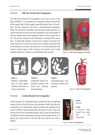
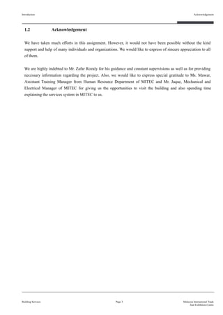
![2.1.3.1.3 Carbon Dioxide Suppression System
Carbon dioxide (CO2) is a colorless, odorless, and chemically inert gas that is both readily available and
electrically non-conductive that leaves no residue behind. This means any sensitive equipment that is in the
protected space is not damaged by the CO2, which reduces downtime and costs. Once the CO2 has dispersed to
safe levels from the protected space, personnel can access any damage from the fire or smoke and quickly get
back to work with no cleanup needed. It extinguishes fire primarily by lowering the level of oxygen that supports
combustion. This mechanism of fire suppression is highly effective, requiring minimal clean-up and is used in
normally unoccupied hazard locations or otherwise avoided by personnel when discharged. In MITEC, each
electrical room has an carbon dioxide suppression system.
Fire Protection System
Building Services
Active Fire Protection System
Page 26 Malaysia International Trade
And Exhibition Centre
Diagram 2.14 System Operation Overview
UBBL 1984
Part VIII: Fire Alarms, Fire Detection, Fire Extinguishment and Fire Fighting Access
[ Section 227 ] Portable Extinguishers
Portable extinguisher shall be provided in accordance with the relevant codes of practice and shall
be sited in prominent positions on exit routes to be visible from all directions and similar
extinguishers in a building shall be of the same method of operation.
Summary (Fire Extinguisher) :
The fire extinguishers system in MITEC meets the UBBL 1984 requirements listed under Section 227, (3). The
fire extinguishers are strategically placed at many locations to be easily accessible by users in the building
during the event of fire.
System Operation
A carbon dioxide fire suppression system eliminates the oxygen to
suppress the fire. The system is equipped with a smoke and heat
detector which will trigger the alarm system and send signal to the fire
control room through the fire control panel upon detecting smoke and
temperature rise. It then releases the carbon dioxide agent into the space
it is protecting. After 30 seconds, all the gas inside will be discharged
through piping, leaving only carbon dioxide inside with the fire curtain
opened and smoke damper closed. The drop in oxygen level quickly
causes the fire to be suppressed or extinguished. On the control panel
outside, if green light lights up, it means that personnel is free to enter
the room whereas if the red light lights up, it means that the carbon
dioxide agent is being discharged and the room cannot be entered.
Extinguishing
Agent
Control
Panel
Detector
Nozzle
(Uniform Building By-Law, 2006, pp. 82) (Original work published in 1984)](https://image.slidesharecdn.com/finalisedb-190727174357/85/MITEC-Building-Service-System-39-320.jpg)
![Fire Protection System
Building Services
Active Fire Protection System
Page 28 Malaysia International Trade
And Exhibition Centre
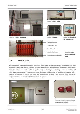
2.1.3.3 Voice Communication System
It is a two-way emergency communication system
connecting fireman intercoms located throughout the
building and a master telephone handset is located in the
fire control room. The fireman intercom handset is being
placed behind a locked door, housed within a red metal
cabinet and rested on a cradle. Lifting the handset from the
cradle will cause the buzzer to sound and light a ‘common
call’ indicator. A maximum call of 7 RFIS and master
handsets can communicate simultaneously.
Figure 2.43 Fireman Intercom located at basement escape
staircase (left) and fire pump room
UBBL 1984
Part VIII: Fire Alarms, Fire Detection, Fire Extinguishment and Fire Fighting Access
[ Section 239 ] Voice Communication System
There shall be two separate approved continuously electrically supervised voice communications
systems, one a fire brigade communications system and the other a public address system between
the central control station and the following areas :
(a) Lifts, lift lobbies, corridors and staircases;
(b) In every office area exceeding 92.9 square metres in area;
(c) In each dwelling unit and hotel guest room where the fire brigade system may be combined
with the public address system.
Summary (Voice Communication System) :
The voice communication system in MITEC meets the UBBL 1984 requirements listed under Section 239. The
two-way communication system ensures the connection between the master handset in the fire control room and
the remote fireman corridor. This allows efficient communication in the event of fire or emergency.
2.1.3.4 Emergency Speaker
The emergency speaker is a network of monitored loud speakers.
The speakers are distributed throughout MITEC to ensure warning
messages and tones satisfy a specific sound pressure level
(volume) and are distinctly audible throughout all required areas
of the building. Also, it ensures warning messages are intelligible
and clearly understood by the occupants.
Figure 2.44
Emergency
Speaker
(Uniform Building By-Law, 2006, pp. 85) (Original work published in 1984)](https://image.slidesharecdn.com/finalisedb-190727174357/85/MITEC-Building-Service-System-41-320.jpg)
![Fire Protection System
Building Services
Active Fire Protection System
Page 29 Malaysia International Trade
And Exhibition Centre
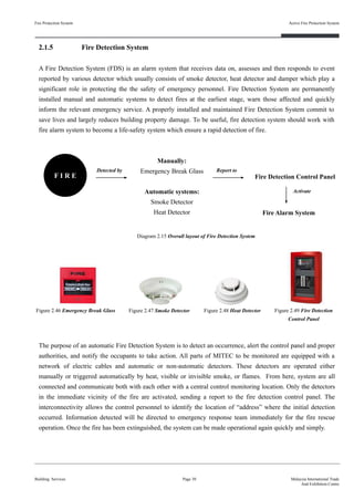
2.1.3.5 Emergency Light
An emergency light is a battery-backed lighting device that
switches on automatically when a building experiences a
power outage. During an event of emergency, it is used to
illuminate the access pathways leading to the exits, fire
staircase, aisles, corridors, ramps and at the exit discharge
pathways towards public area. The level of illumination and
quality consistency of emergency illumination are the crucial
factors to the safety occupants during evacuation.
UBBL 1984
Part VIII: Fire Alarms, Fire Detection, Fire Extinguishment and Fire Fighting Access
[ Section 253 ] Emergency power system
(1) Emergency power system shall be provided to supply illumination and power automatically
in the vent of failure of the normal supply or in the event of accident to elements of the
system supplying power and illumination essential for safety of life and property.
(5) Current supply shall be such that in the event of failure of the normal supply to or within the
buildings concerned, the emergency lighting or emergency power, or both emergency
lighting and power will be available within 10 seconds of the interruption of the normal
supply. The supply system for emergency purposes shall comprise one of the following
approved types:
(a) Storage Battery
Storage Battery of suitable rating and capacity to supply and maintain at not less
than 871/2 percent of the system voltage the total of the circuits supplying
emergency lighting and emergency power for a period of at least 11/2 hours;
(b) Generator set
A generator set driven by some form of prime mover and of sufficient capacity and
proper rating to supply circuit carrying emergency lighting or lighting and power
with suitable means for automatically starting the prime mover on failure on the
normal service.
Summary (Emergency Light) :
The emergency light system in MITEC meets the UBBL 1984 requirements listed under Section 253, (1) and (5).
The emergency lights are well-maintained and equipped with storage battery to ensure proper lighting during the
event of emergency.
Figure 2.45 Emergency light
(Uniform Building By-Law, 2006, pp. 88) (Original work published in 1984)](https://image.slidesharecdn.com/finalisedb-190727174357/85/MITEC-Building-Service-System-42-320.jpg)
![Fire Protection System
Building Services
Active Fire Protection System
Page 33 Malaysia International Trade
And Exhibition Centre
UBBL 1984
Part VII: Fire Requirements
[ Section 153 ] Smoke detectors for lift lobbies
(1) All life lobbies shall be provided with smoke detectors.
(2) Lift not opening into a smoke lobby shall not use door reopening devices controlled by light
beam or photodetectors unless incorporated with a force close feature which after thirty
seconds of any interruption of the beam cause the door to close within a preset time.
Part VIII: Fire Alarms, Fire Detection, Fire Extinguishment and Fire Fighting Access
[ Section 225 ] Detecting and extinguishing fire
(1) Every building shall be provided with means of detecting and extinguishing fire and with
fire alarms together with illuminated exit signs in accordance with the requirements as
specified in the Tenth Schedule to these By-laws.
(Uniform Building By-Law, 2006, pp. 58, 82) (Original work published in 1984)
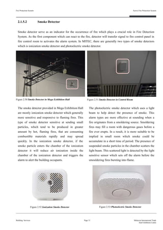
Summary (Smoke Detector) :
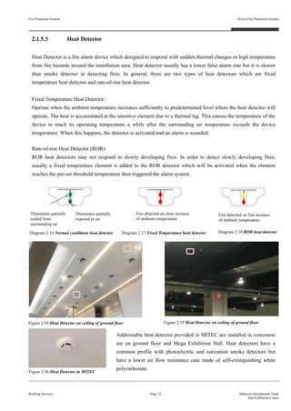
Smoke detectors and heat detectors in MITEC does fulfill the requirements stated in By-laws under Section 153
and Section 225. Both of the detector are installed on the ceiling level of the lift lobbies area in every floor to
detect fire hazard. They work together with fire alarm bell can be remotely controlled from the fire control room
as well.
Figure 2.57 Smoke and heat detectors in lift lobby
Smoke Detector
Heat Detector](https://image.slidesharecdn.com/finalisedb-190727174357/85/MITEC-Building-Service-System-46-320.jpg)
![Fire Protection System
Building Services
Active Fire Protection System
Page 35 Malaysia International Trade
And Exhibition Centre
UBBL 1984
Part VII: Fire Requirements Fighting Access
[ Section 237 ] Fire Mode of Operation
(1) The fire mode of operation shall be initiated by a signal from the fire alarm panel which
may be activated automatically by one of the alarm devices in the building or manually
Summary (Fire Alarm Control Panel) :
The Fire Alarm Control Panel in MITEC complies with the UBBL 1984 requirements listed under Section
155(1). The fire alarm control panel is equipped with fire mimic diagram for each floor in the building to allow
efficient signal identification during fire emergency
(Uniform Building By-Law, 2006, pp. 85) (Original work published in 1984)
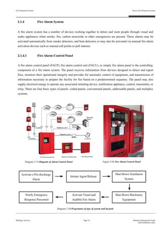
2.1.4.1 Fire Alarm Bell
A fire alarm is an electronic sounder or a bell. The alarm makes a loud, high pitched sound to notify people that
there is a fire in the building. Fire alarms may be activated automatically from smoke detectors, and heat
detectors. When a fire occur, the smoke detector and heat detector will send a signal to the fire alarm control
panel to activate the alarm bell. In MITEC, the alarm bells are installed at escape corridor and car park area. It
provides alert to the occupants in the building and detailed information as to the location of the fire occurred to
meet the needs of firefighting and detection system with central control equipment.
Diagram 2.21 Fire Alarm SystemFigure 2.59 Fire Alarm Bell](https://image.slidesharecdn.com/finalisedb-190727174357/85/MITEC-Building-Service-System-48-320.jpg)
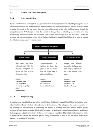
![2.1.4.2 Manual Call Point
A manual call point is a device which enables personnel to raise an alarm in the event of a fire incident by
pressing a frangible element to activate the alarm system. A fire alarm call point should also be spaced so that
one may always be found within a maximum distance of 30m apart. The manual call points are located nearby
the exits and doorways for the occupants of the building to break the glass therefore a warning signal will then
send to the fire alarm control panel. In MITEC, manual call point were installed at a height of 1.4m above floor
level at easily accessible and conspicuous positions. This includes on exit routes, at the entry floor landing of
staircases and at all exits to the open air. It is a quick means for a person who does not have access privileges to
certain information to gain access when necessary. It is intended to specifically cover emergency cases and the
switch is used to cut electric circuit immediately. User authentication system is used to control and monitor
access to sensitive data. It is designed to preserve security by restricting access.
Fire Protection System
Building Services
Active Fire Protection System
Page 36 Malaysia International Trade
And Exhibition Centre
Exits /
Doorways
Manual Call
Point
Figure 2.60 Indication of location of Manual Call point Figure 2.61 Manual Call Point
UBBL 1984
Part VII: Fire Alarms, Fire Detection, Fire Extinguishment and Firefighting Access
[ Section 237 ] Fire Alarms
(1) Fire alarms shall be provided in accordance with the Tenth Schedule to there By-Laws.
(2) All premises and building with gross floor area excluding car park and storage areas
exceeding 9290 square metres or exceeding 30.5 metres in height shall be provided with a
two-storage alarm system with evacuation (continuous signal) to be given immediately in
the affected section of the premises while an alert (intermittent signal) be given in
adjoining section
(3) Provision shall be made for the general evacuation of the premises by action of master
control
(Uniform Building By-Law, 2006, pp. 85) (Original work published in 1984)](https://image.slidesharecdn.com/finalisedb-190727174357/85/MITEC-Building-Service-System-49-320.jpg)
![Fire Protection System
Building Services
Active Fire Protection System
Page 37 Malaysia International Trade
And Exhibition Centre
[ Section 240 ] Electrical isolation switch
(1) Every floor or zone of any floor with a net area exceeding 929 square metres shall be
provided with an electrical isolation switch located within a staircase enclosure to permit
the disconnection of electrical power supply to the relevant floor or zone served
(2) The switch shall be of a type similar to the fireman’s switch specified in Institution of
Electrical Engineers Regulation then in force
Summary (Manual Call Point) :
The fire alarm bell and manual call point used in MITEC complies to the UBBL 1984 requirements listed under
Section 237 (1) , (2) , (3) and Section 240 (1) (2). These systems are placed on every floor of the building at the
escape corridor to allow disconnection of electrical power in any case of emergency.
(Uniform Building By-Law, 2006, pp.85) (Original work published in 1984)](https://image.slidesharecdn.com/finalisedb-190727174357/85/MITEC-Building-Service-System-50-320.jpg)
![Fire Protection System
Building Services
Passive Fire Protection System
Page 39 Malaysia International Trade
And Exhibition Centre
UBBL 1984
Part VII: Fire Requirements
[ Section 134 ] Designation of purpose groups
For the purpose of this Part every building or compartment shall be regarded according to its use or
intended use as falling within one of the purpose groups set out in the Fifth Schedule to these
By-laws and, where a building is divided into compartments used or intended to be used for
different purposes, the purpose group of each compartment shall be determined separately:
Provided that where the whole or part of the building or compartment, as the case may be, is used or
intended to be used for more than one purpose, only the main purpose of use of that building or
compartment shall be taken into account in determining into which purpose group it falls.
Summary (Purpose Group):
MITEC serves as a place of assembly which offers 13 meeting rooms in various sized that can be configured for
a multitude of functions, such as conference, ballroom, concerts, indoor sports and exhibition hall. The purpose
group of MITEC are compartmented and regarded accordingly while complies with the to the UBBL 1984, Part
VII: Fire Requirements, with the purpose group of IV (Office) and VII (Places of Assembly) The user group
within MITEC is centered around office workers and professionals.
(Uniform Building By-Law, 2006, pp. 45, 46, 47) (Original work published in 1984)](https://image.slidesharecdn.com/finalisedb-190727174357/85/MITEC-Building-Service-System-52-320.jpg)
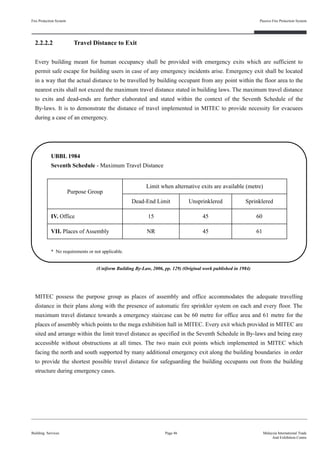
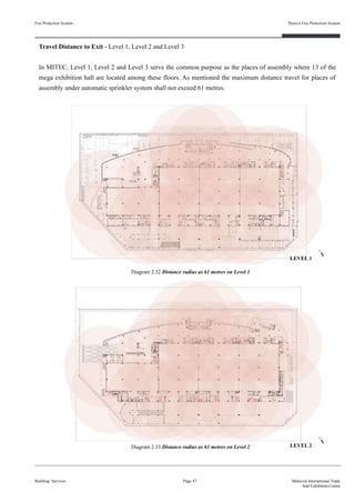
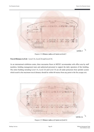
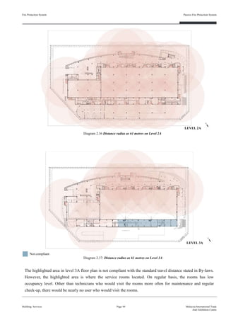
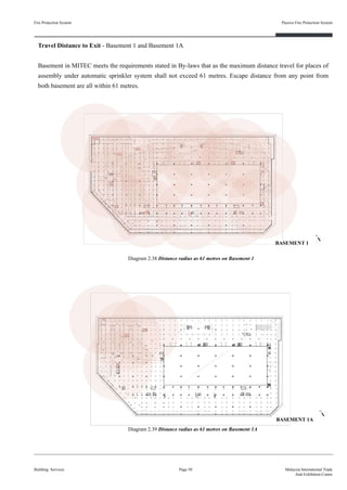
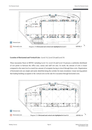
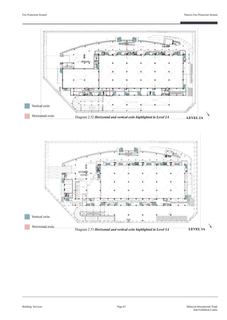
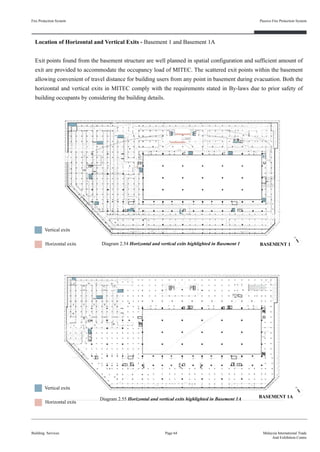
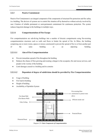
![Summary (Travel Distance to Exit) :
As shown in all the diagrams above, all exit points are arranged within the maximum travel distance for building
occupants to escape the building in the shortest time possible in case of emergency. The spacious concourse area
on ground level able to escort building users escape from the building even during high occupancy level. Other
than the insufficient vertical exit on level 3A which has less occupants since most of the rooms are service
rooms, evacuation routes in MITEC are well-designed and efficiently planned, exit points provided are obvious
and unobstructed at all times. To conclude, the measurement of distance travel to exit within MITEC meets the
requirement stated in By-laws under Section 165 (1), Section 166 (1), (2) and Section 169.
Fire Protection System
Building Services
Passive Fire Protection System
Page 51 Malaysia International Trade
And Exhibition Centre
UBBL 1984
Part VII: Fire Requirements
[ Section 165 ] Measurement of travel distance to exits
(1) The travel distance to an exit shall be measured on the floor or other walking surface along
the centre line of the natural path of travel, starting 0.300 metre from the most remote
point of occupancy, curving around any corners or obstructions with 0.300 metre clearance
therefrom and ending at the storey exit. Where measurement includes stairs, it shall be
taken in the plane of the trend noising.
[ Section 166 ] Exits to be accessible at all times
(1) Except as permitted by by-law 167 not less than two separate exits shall be provided from
each storey together with such additional exits as may be necessary.
(2) The exits shall be so sited and the exit access shall be so arranged that the exits are within
the limits of travel distance as specified in the Seventh Schedule to these By-laws and are
readily accessible at all times.
[ Section 169 ] Exit route
No exit route may reduce in width along its path of travel from the storey exit to the final exit.
(Uniform Building By-Law, 2006, pp. 62, 63) (Original work published in 1984)](https://image.slidesharecdn.com/finalisedb-190727174357/85/MITEC-Building-Service-System-64-320.jpg)
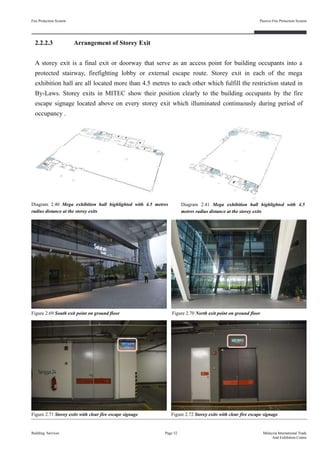
![Summary (Arrangement of Storey Exit) :
The arrangement of storey exits in MITEC are complies to the restriction stated in By-laws in which the distance
between two storey exits is more than 4.5 metres to ensure a constant and stable flow of circulation. Every storey
exits is provided with a clear escape signage positioned above the fire-rated door. An effective designated
evacuation route required to work with a proper well planned storey exit to maximise the quality of fire escape
route.
Fire Protection System
Building Services
Passive Fire Protection System
Page 53 Malaysia International Trade
And Exhibition Centre
UBBL 1984
Part VII: Fire Requirements
[ Section 167 ] Storey exits
(1) Except as provided for in By-laws 194 every compartment shall be provided with at least
two storey exits located as far as practical from each other in no case less than 4.5 metres
and in such position that the travel distances specified in the Seventh Schedule to these
By-laws are not exceeded.
(2) The width of storey exits shall be accordance with the provisions in the Seventh Schedule
to these By-laws.
[ Section 172 ] Emergency exits sign
(1) Storey exits and access to such exits shall be marked by readily visible signs and shall not
be obscured by any decorations, furnishings or other equipment.
(2) Every exit sign shall have the word “KELUAR” in plainly legible letters not less than 150
millimetres high with the principal strokes of the letters not less than 18 millimetres wide.
The lettering shall be in red against a black background.
(3) All exit signs shall be illuminated continuously during periods of occupancy.
[ Section 174 ] Arrangement of storey exits
(1) Where two or more storey exits are required they shall be spaced at not less than 5 metres
apart measured between the nearest edges of the openings.
(2) Each exit shall give access to -
(a) A final exit;
(b) A protected staircase leading to a final exit; or
(c) An external route leading to a final exit.
(3) Basements and roof structures used solely for services need not be provided with
alternative means of egres.
(Uniform Building By-Law, 2006, pp. 63, 64, 65) (Original work published in 1984)](https://image.slidesharecdn.com/finalisedb-190727174357/85/MITEC-Building-Service-System-66-320.jpg)
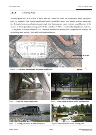
![Summary (Assembly Point) :
MITEC category under Class A place of assembly which able to accommodate up to 60,000 occupants in the
building. Two of the main exits are supported by additional exits on ground floor that lead to assembly point also
complies with Section 183. The assembly point provided within the open parking area located about 50 meters
away from the building which are at a distant from danger. To conclude, the assembly point of MITEC is a
suitable spot to evacuate in case of an emergency which meets the requirement stated in By-laws under Section
178, Section 179 and Section 183 (b), (c) and (d).
Fire Protection System
Building Services
Passive Fire Protection System
Page 55 Malaysia International Trade
And Exhibition Centre
UBBL 1984
Part VII: Fire Requirements
[ Section 178 ] Exits for institutional and places of assembly
In building classified as institutional or places of assembly, exits to a street or large open space,
together with staircases, corridors and passages leading to such exits shall be located, separated or
protected as to avoid any undue danger to the occupants of the place of assembly from fire
originating in the other occupancy or smoke therefrom.
[ Section 179 ] Classification of places of assembly
Each place of assembly shall be classified according to its capacity as follows:
Class A - Capacity …… 1,000 persons or more
Class B - Capacity …… 300 to 1,000 persons
Class C - Capacity …… 100 to 300 persons
[ Section 183 ] Exit details for places of assembly
Every place of assembly, every tier or balcony and every individual room used as a place of
assembly shall have exits sufficient to provide for the total capacity thereof as determined in
accordance with by-law 180 and as follows:
(b) doors leading outside the building at ground level or not more than three risers above or
below ground one hundred persons per exit unit;
(c) staircases or other types of exit not specified in by-law 177 above seventy-five persons
per exit unit;
(d) every Class A place of assembly (capacity one thousand persons or more) shall have at
least four separate exits as remote from each other as practicable;
(Uniform Building By-Law, 2006, pp. 66, 67) (Original work published in 1984)](https://image.slidesharecdn.com/finalisedb-190727174357/85/MITEC-Building-Service-System-68-320.jpg)
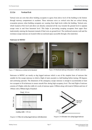
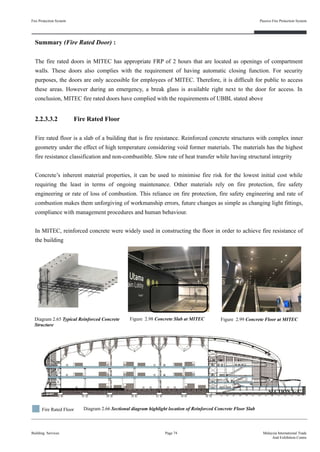
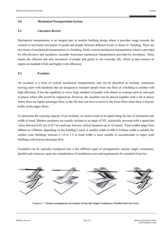
![2.2.2.5 Horizontal Exit
Horizontal exit are the exit discharge occupant to another side of a building along a protected path of egress
travel in a horizontal direction. This category of exit points provide an additional layer of fire resistive protection
from the fire source by using firewall or fire barrier to secure building occupants towards the exit components. In
MITEC, the horizontal exits include the fire fighting lobby, lift lobby, corridor and fire-protected pathway that
lead towards the emergency escape staircase accessed through fire-rated doors. In case of emergency,
compartmented building as MITEC allow building occupants to utilise the fire rated door as a separation from
the origin of fire section to one another.
Fire Protection System
Building Services
Passive Fire Protection System
Page 56 Malaysia International Trade
And Exhibition Centre
Figure 2.77 Horizontal exits access from basement to fire lobby Figure 2.78 Horizontal exit in between basement and lift lobby
UBBL 1984
Part VII: Fire Requirements
[ Section 171 ] Horizontal exits
(1) Where appropriate, horizontal exits may be provided in lieu of other exits.
(2) Where horizontal exits are provided protected staircases and final exits need only be of a
width to accommodate the occupancy load of the larger compartment or building
discharging into it so long as the total number of exit widths provided is not reduced to less
than half that would otherwise be required for the whole building.
(Uniform Building By-Law, 2006, pp. 64) (Original work published in 1984)
Summary (Horizontal Exits) :
Horizontal exits in MITEC meet the requirement stated in By-laws. In reference with the evacuation route, all
horizontal exits are placed in leading to fire escape staircase whilst the ground floor provide sufficient amount of
horizontal exits which can be easily identifies for occupants to egress off the building structure with ease.](https://image.slidesharecdn.com/finalisedb-190727174357/85/MITEC-Building-Service-System-69-320.jpg)
![Fire Protection System
Building Services
Passive Fire Protection System
Page 60 Malaysia International Trade
And Exhibition Centre
UBBL 1984
Part VII: Fire Requirements
[ Section 106 ] Dimensions of staircases
(1) In any staircase, the riser of any staircase shall be not more than 180 millimetres and the
tread shall be not less than 255 millimetres and the dimensions of the rise and the tread of
the staircase so chosen shall be uniform and consistent throughout.
(2) The widths of staircases shall be in accordance with By-laws 168.
(3) The depths of landing shall be not less than the width of the staircases.
[ Section 168 ] Staircases
(1) Except as provided for in By-laws 194 every upper floor shall have means of egress via at
least two separate staircases.
(2) Staircases shall be of such width that in the event of any one staircase not being available
for escape purposes the remaining staircases shall accommodate the highest occupancy
load of any one floor discharging into it calculated in accordance with provisions in the
Seventh schedule to these By-laws.
(3) The required width of a staircase shall be the clear width between walls but handrails may
be permitted to encroach on this width to a maximum of 75 millimetres.
(4) The required width of a staircase shall be maintained throughout its length including at
landings.
(5) Doors giving access to staircase shall be so positioned that their swing shall no point
encroach on the required width of the staircase or landing.
[ Section 198 ] Ventilation of staircase enclosures
(1) All staircases enclosures shall be ventilation at each floor or landing levels by either
permanent openings or openable windows to the open air having a free area of not less
than 1 square metre per floor.
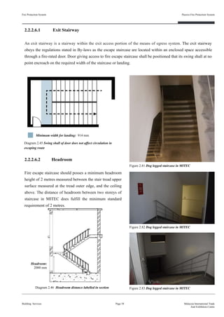
Summary (Vertical Exits) :
All of the vertical exits found in MITEC complies with the By-laws stated in Section 106, Section 168 and
Section 198. Dimension of tread and riser of fire escape staircase are all in suitable and constant length and
width throughout the evacuation route to prevent accident. The 900mm width of fire-rated door create a door
swing that does not intersect with the required width of landing. Designated travelling path keep ventilated and
unobstructed by providing a clear flow of movement during tie of egress as the vertical exits provided in MITEC
act in accordance to the requirement.
(Uniform Building By-Law, 2006, pp. 39, 63, 71) (Original work published in 1984)](https://image.slidesharecdn.com/finalisedb-190727174357/85/MITEC-Building-Service-System-73-320.jpg)
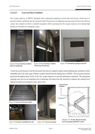
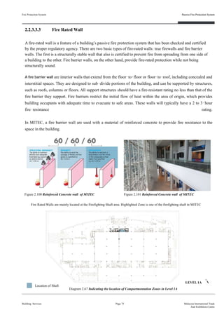
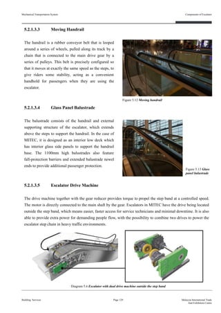
![2.2.2.7 Handrail
Rail which designed to be grasped by hand to provide stability and support while ascending or descending
stairways in order to prevent injurious falls. Staircase which more than 4 flights shall be provided with at least
one handrail beside the staircase. Handrails provided in MITEC are mostly embedded directly into the wall
structure while some of the handrail are subjected the ground to achieve a better support for building occupants
Fire Protection System
Building Services
Passive Fire Protection System
Page 65 Malaysia International Trade
And Exhibition Centre
Figure 2.90 Fire escape staircase provided with handrails
UBBL 1984
Part VI: Constructional Requirements
[ Section 107 ] Handrails
(1) Except for staircases of less than 4 risers, all staircases shall be provided with at least one
handrail.
(2) In building other than residential buildings, a handrail shall be provided on each side of the
staircase when the width of the staircase is 1100 millimeters or more.
(3) All handrails shall project not more than 100 millimetres from the face of the finishing wall
surface and shall be located not less than 825 millimetres and not more than 900 millimetres
measured from the nosing of the treads provided that handrails to landings shall not be less
than 900 millimetres from the level of the landing.
(Uniform Building By-Law, 2006, pp. 39) (Original work published in 1984)
Handrail provided on each side of staircase
Wall mounted handrail
Width of staircase : 1200mm
Height of handrail : 900mm
Summary (Handrails) :
Handrails provided in MITEC complies to Section 107 stated in By-laws which width that exceed 1100mm shall
cater with two handrails at each side of the staircase. The height of staircase also maintain within the suitable
range listed in building law with a minimum of 900mm.](https://image.slidesharecdn.com/finalisedb-190727174357/85/MITEC-Building-Service-System-78-320.jpg)
![Fire Protection System
Building Services
Passive Fire Protection System
Page 70 Malaysia International Trade
And Exhibition Centre
UBBL 1984
Part VIII: Fire Requirements
[ Section 136 ] Provision of Compartment Walls and Compartment Floors
Any building, other than a single storey building, of a purpose group specified in the Fifth
Schedule to these By-Laws and which has -
(a) Any storey the floor area of which exceeds that specified as relevant to a building of that
purpose group and height ; or
(b) A cubic capacity which exceeds that specified as so relevant shall be so divided into
compartments, by means of compartment walls or compartment floors or both, that -
(i) No such compartment has any storey the floor area of which exceeds the area specified has a
relevant to that building ; and
(ii) No such compartment has a cubic capacity which exceeds that specified a so relevant to that
building;
Provided that if any building is provided which an automatic sprinkler installation which
complies with the relevant recommendations o the F.OC Rules or Automatic Sprinkler
Installation, 29th edition, this by-law has effect in relation to that building as if the limits of
dimension specified are doubled
[ Section 137 ] Floor in Building exceeding 30 metres in height to be Constructed as
Compartment Floor
In any building which 30 metres in height, any floor which is more than 9 metres above ground
floor level which separates are storey from another storey, other than a floor which is either
within maisonette or a mezzanine floor shall be constructed as a compartment floor
[ Section 139 ] Separation of Fire Risk Areas
The following areas or users shall be separated from the other areas of the occupancy in which
they are located by fire resisting construction of elements of structure of a FRP to be determined
by the local authority based on the degree of hire hazard ;
(a) boiler rooms and associated fuel storage areas](https://image.slidesharecdn.com/finalisedb-190727174357/85/MITEC-Building-Service-System-83-320.jpg)
![Fire Protection System
Building Services
Passive Fire Protection System
Page 71 Malaysia International Trade
And Exhibition Centre
(b) laundries
(c) Repair shops involving hazardous processes and materials ;
(d) Storage areas of materials in qualities deemed hazardous ;
(e) Liquified petroleum gas storage areas ;
(f) linen rooms ;
(g) Transformer rooms and Substations ;
(h) Flammable liquid stores
[ Section 189 ] Enclosing Means of Escape in Certain Buildings
(1) Every staircase provided under these By-laws in a building of four storey or more, or in a
building where the highest floor level is more than 1200 millimetres above the ground level, or in
any place of assembly, or in any school when such staircase is to be used as an alternative means of
escape shall be enclosed shall be enclosed throughout its length with fire resisting materials.
(2) Any necessary openings, except openings, except openings in external walls which shall not for
the purpose of this by-law include walls to air-wells, in the length of such staircase shall be provided
with self-closing doors constructed of fire-resisting materials.
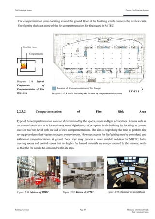
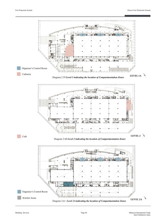
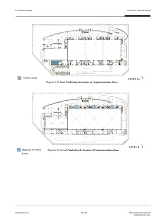
Summary (Fire Compartmentation) :
The compartmentation of MITEC meets the UBBL 1984 requirements stated. From Diagram 2.59 to Diagram
2.63, the compartation of means of escape and fire risk areas meets the by-laws. MITEC exceed 30 metres
height, therefore, it is required to have compartment floor. Spaces that deemed hazardous are compartmentalize
by fire-resistive components to avoid spread of fire during fire emergency and allow the occupants in the
building to escape.
(Uniform Building By-Law, 2006, pp. 51,52,67) (Original work published in 1984)](https://image.slidesharecdn.com/finalisedb-190727174357/85/MITEC-Building-Service-System-84-320.jpg)
![Fire Protection System
Building Services
Passive Fire Protection System
Page 73 Malaysia International Trade
And Exhibition Centre
UBBL 1984
Part VII: Fire Requirements
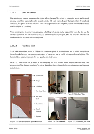
[ Section 162 ] Fire Doors in Compartment walls and separating walls
(1) Fire doors of the appropriate FRP shall be provided
(2) Openings in compartment walls and separating walls shall be protected by a fire door having
a FRP in accordance with the requirements for that wall specified in the Ninth Schedule to
these By-Laws
(3) Openings in protecting structures shall be protected by fire doors having FRP of not less
than half the requirements for the surrounding wall specified in the Ninth Schedules to these
By-Laws but in no case less than half hour
(4) Openings in partitions enclosing a protected corridor or lobby shall be protected by ire doors
having RP of half-hour
(5) Fire doors including frames shall be constructed to a specification which can be shown to
meet the requirements for the relevant FRP when tested in accordance with section 3 of
BS476:1951
[ Section 164 ] Door Closers for Fire Doors
(1) All the fire doors shall be fitted with automatic door closers of the hydraulically spring
operated type in case of sliding doors
(2) Double doors with rebated meeting stiles shall be provided with coordinating device to
ensure that leafs close in the proper sequence
(3) Fire doors may be held open provided the hold open device incorporates a heat actuated
device to release the door. Heat actuated devices shall not be permitted on fire doors
protecting openings to protected corridors or protected staircases
[ Section 173 ] Exit Doors
(1) All exit doors shall be openable from inside without the use of key or any special knowledge
or effort
(2) Exit doors shall close automatically when released and all door devices including magnetic
door holder, shall release the doors upon power failure or actuation of the fire alarm
(Uniform Building By-Law, 2006, pp. 60, 62, 64, 65) (Original work published in 1984)](https://image.slidesharecdn.com/finalisedb-190727174357/85/MITEC-Building-Service-System-86-320.jpg)
![UBBL 1984
Part VIII: Fire Requirements
[ Section 143 ] Beam or Column
Any beam or column forming part of, and any structure arrying, and external wall which is required
to be constructed of non-combustible materials shall comply with the provisions of paragraph (3) od
By-Law 142 as to non-combustibility
[ Section 147 ] Construction of Separating wall
(1) Any separating wall, other than a wall separating buildings not divided into compartments
within the limits of size indicated by the letter “X” in Part I of the Ninth Schedule to there
By-Laws, shall be constructed wholly of non-combustible materials, excluding any surface
finish to a wall complies with the requirements of thee By-laws and the required FRP for the
wall shall be obtained without assistance from such non-combustible material
(2) Any beam or column forming part of, and any structure carrying, a separating wall which is
required to be constructed of non-combustible materials shall itself comply with the
requirements of paragraph (1) as to non-combustibility
Fire Protection System
Building Services
Passive Fire Protection System
Page 77 Malaysia International Trade
And Exhibition Centre
(Uniform Building By-Law, 2006, pp. 54, 55) (Original work published in 1984)
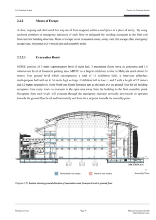
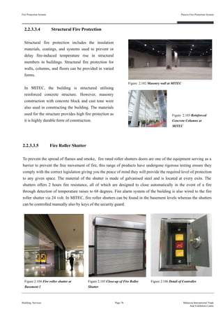
Summary (Structural Components) :
The structural components of MITEC have respected the laws of UBBL in the categories stated above.
Therefore, we can conclude that the structure of MITEC is sufficient remain stable while the fire fighters
perform rescue for a certain period of time.
Aluminium Box Top
Caps for Guide Rail
ControllerSide Frame
Guide Rail
End Slat
Aluminium Slats
Diagram 2.68 Components of Fire Roller Shutter
Aluminium Box Bottom](https://image.slidesharecdn.com/finalisedb-190727174357/85/MITEC-Building-Service-System-90-320.jpg)
![Fire Protection System
Building Services
Passive Fire Protection System
Page 79 Malaysia International Trade
And Exhibition Centre
UBBL 1984
Part VIII: Fire Requirements
[ Section 140 ] Fire Appliance Access
All buildings in excess of 7000 cubic metres shall abut upon a street or road or open space of not
less than 12 metres width and accessible to fire brigade appliances. The proportion of the building
abutting the street, road or open spaces shall be in accordance with the following scale :
Summary (Fire Engine Access) :
MITEC has a volume of approximately 1,165,680m³. The width of the neighbouring street for fire fighting
access is 13m. MITEC proportion of building abutting street comply with the 12 metres requirement stated in
By-laws. Hence, there will be a low tendency of slow traffic occur to the fire engine access, facilitating the
rescue attempt during the event of fire
(Uniform Building By-Law, 2006, pp. 52) (Original work published in 1984)
Volume of building in cubic meter Minimum proportions of perimeter of
building
7000 to 28000 One - sixth
2800 to 56000 One - Fourth
56000 to 84000 One - Half
84000 to 112000 Three - Fourths
112000 and above Island Site](https://image.slidesharecdn.com/finalisedb-190727174357/85/MITEC-Building-Service-System-92-320.jpg)
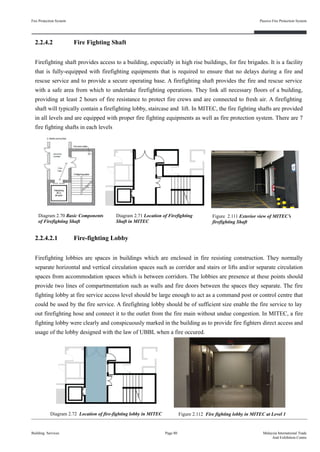
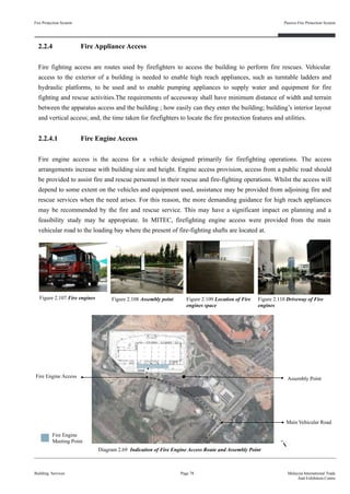
![Summary (Firefighting Shaft) :
The firefighting shafts in MITEC meets the requirements stated by the UBBL above. The fire lobbies are
well-equipped and the number of lobbies is sufficiently enough to fulfil the overall safety criteria of the building,
Fire Protection System
Building Services
Passive Fire Protection System
Page 83 Malaysia International Trade
And Exhibition Centre
UBBL 1984
Part VIII: Fire alarms, fire detection, fire extinguishment and fire fighting access
[ Section 229] Means of access and fire fighting in buildings over 18.3 metres high access
(1) Buildings in which the topmost floor i more than 18.3 metres above fire appliances access
level shall be provided with means of gaining access and fighting fire from within the
building consisting of fire fighting access lobbies, fire fighting staircases, fire lifts and dry
or wet rising systems
(2) Fire fighting access lobbies shall be provided at every floor level and shall be located that
the level distance from the furthermost point of the floor does not exceed 45.75 metres
(3) A fire fighting staircase shall be provided to give direct access to each fire fighting access
lobby and shall be directly accessible from outside the building at fire appliance level. This
may be one of the staircase required as a means of egress from the building
(4) The fire lift shall be discharged directly into the fire fighting access lobby, fire fighting
staircase or shall be connected to it by a protected corridor
(5) A fire lift shall be provided to give access to each fire-fighting access lobby or in the
adsense of a lobby to the fire-fighting staircase at each floor level
(6) The fire lift shall discharge directly into the fire-fighting access lobby fire-fighting staircase
or shall be connected to it by a protected corridor
[ Section 243] Fire Lifts
(1) In a building where the top occupied floor is over 18.5 metres above the fire appliance
access level fire lifts shall be provided
(2) A penthouse occupying not more than 50% of the area of the floor immediately below shall
be exempted from this measurement
(3) The fire lifts shall be located within a separate protected shaft if it opens into a separate
lobby
(4) Fire lifts shall be provided as the rate of one lift in every group of lifts which discharge into
the some protected enclosure or smoke lobby containing the rising main, provided that the
ire lifts are located not more than 61 metres travel distance from the furthermost point of the
floor.
(Uniform Building By-Law, 2006, pp. 83, 86) (Original work published in 1984)](https://image.slidesharecdn.com/finalisedb-190727174357/85/MITEC-Building-Service-System-96-320.jpg)

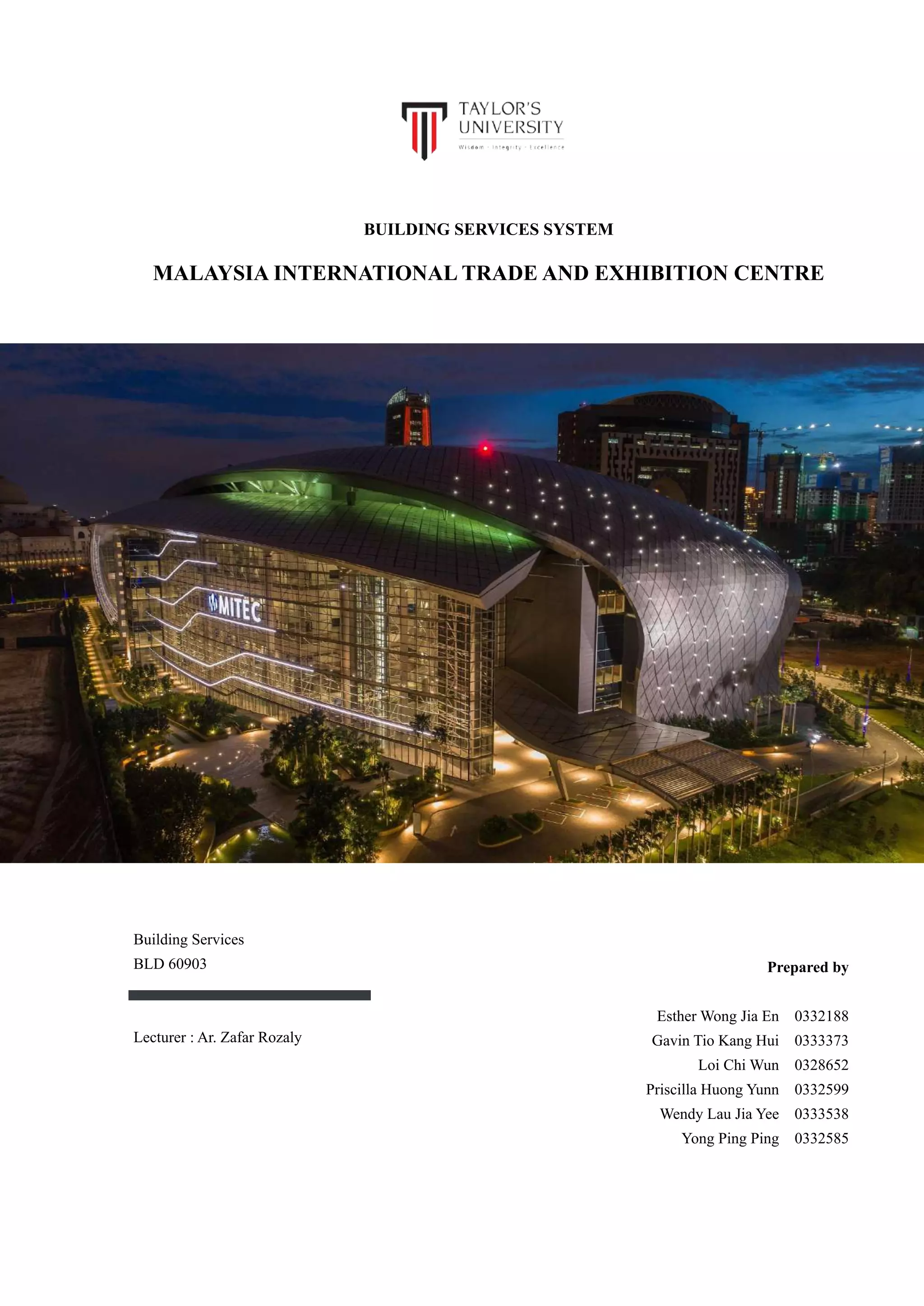
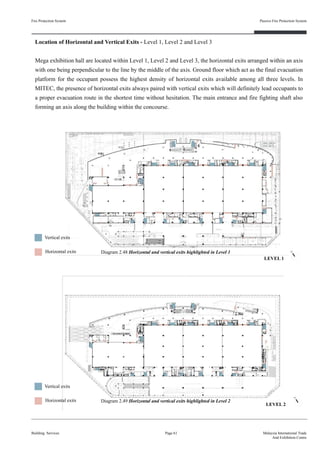
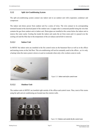
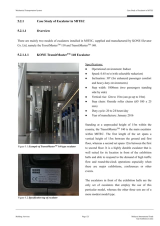
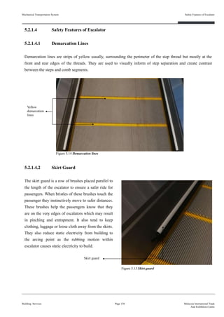
![3.3 Case study of MITEC for Air-Conditioning System
In the MITEC building, there are 2 types of air-conditioning system which are the centralized air-conditioning
system and the split air-conditioning system. The main air-conditioning system is the centralized
air-conditioning while the split air-conditioning system in MITEC is used only in the fire control room and as
backup air-conditioning when the main system is down.
3.3.1 Chilled Water Central Air-Conditioning System
Air-conditioning System
Building Services
Air conditioning system
Page 87 Malaysia International Trade
And Exhibition Centre
UBBL 1984
Part III: Space, Light and Ventilation
[ Section 41 ] Mechanical ventilation and air-conditioning (3):
The provisions of the Third Schedule By-Law shall apply to buildings which are mechanically
ventilated or air-conditioned.
Diagram 3.1 Introduction of components in an
air-conditioning system
(Source : Khemani , 2009)
(Uniform Building By-Law, 2006, pp. 18, 19) (Original work published in 1984)
In the MITEC building, majority of the
building is air-conditioned by the chilled
water central air-conditioning system . It
comprises of centralized duct system,
consisting an air handling unit, air supply
system , air return duct and grilled that
circulate warm air from furnace cooled
air to spaces. The warm air from the
spaces is then returned back to the
system to be cooled down again.](https://image.slidesharecdn.com/finalisedb-190727174357/85/MITEC-Building-Service-System-100-320.jpg)
![3.4 Conclusion
Analysis :
● Air-conditioning system in MITEC are very well maintains and strategically planned out. Machines that
produce very large sounds such as the chillers are placed in the basement away from the halls and
meeting rooms, the interior of the chiller plant room is also covered will paddings of sponges to block of
the sound from causing disturbance.
● Most of the room ventilation are using air-conditioner as the main purpose for the building. There is also
back up electricity machine to store electricity when there is a case of sudden cut off electricity in the
middle of utilizing the rooms. Thus, in any case of air-conditioning is spoilt , mechanical ventilation will
be provided to ventilate the space.
In conclusion, the Chilled Water Central Air Conditioning System and the Split Unit System of MITEC has
compiled with all the By Laws stated in UBBL section 41 as well as MS1525 : 2014 which are the guidelines
for mechanical ventilation and air conditioning set by the government to be followed. With sufficient facilities,
regular maintenance and back-up plans are planned and designed for the halls , meeting rooms and offices, this
ensures the thermal comfort of the environment in MITEC is achieved.
Building Services
Air conditioning system
Page 96 Malaysia International Trade
And Exhibition Centre
UBBL 1984
Part III: Space, Light and Ventilation
[ Section 41 ] Mechanical ventilation and air-conditioning
(2) Any application for the waiver of the relevant By-Law shall only be considered if in
addition to the permanent air conditioning system there is provide alternative approved
means of ventilating the air conditioned enclosure, such the within half an hour of the
conditioning system failing, not less than the stipulated volume of the fresh air specified
here in after shall introduced into the enclosure during the period of air conditioning system
is not functioning.
Air-conditioning System
(Uniform Building By-Law, 2006, pp. 18) (Original work published in 1984)](https://image.slidesharecdn.com/finalisedb-190727174357/85/MITEC-Building-Service-System-109-320.jpg)

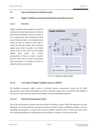
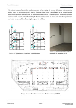
![Mechanical Ventilation System
Building Services
Staircase pressurisation system
Page 111 Malaysia International Trade
And Exhibition Centre
UBBL 1984
Part VII: Fire Requirements
[ Section 198] Ventilation of staircase enclosures
(1) All staircase enclosures shall be ventilated at each floor of landing level by either permanent
openings or openable windows to the open air having a free area of not less than 1 square
metre per floor.
[ Section 202 ] Pressurized system for staircase
All staircases serving buildings of more than 47.75 metres in height where there is no adequate
ventilation as required shall be provided with a basic system of pressurization--
(a) Where the air capacity of the fan shall be sufficient to maintain an air flow of not less than
60 metres per minute through the doors which are deemed to be open;
(b) Where the number of doors which are deemed to be opened at the one time shall be 10% of
the total number of doors opening into the staircase with a minimum number of two doors
open;
(c) Where with all the doors closed the air pressure differential between the staircases and the
areas served by it shall not exceed 5 millimetres water gauge.
(d) Where the mechanical system to prevent smoke from entering the staircases shall be
automatically activated by a suitable heat detecting device, manual or automatic alarm or
automatic wet pipe sprinkler system;
(e) Which meets the functional requirements as may be agreed with the D.G.F.S.
Summary :
The staircase pressurization system in MITEC meets the requirement stated in UBBL 1984 under section 202.
The pressurization system is provided for each enclosed staircase in the building. It is well-maintained and still
functioning to supply air from outside to pressurize the stairwell during fire emergency.
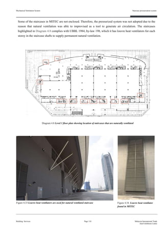
The natural ventilated staircase in MITEC has fulfil the UBBL requirements of which vent louvres can achieve
the same purposes of securing air circulation without the necessary to install a pressurized system for staircase.
(Uniform Building By-Law, 2006, pp. 71, 72) (Original work published in 1984)](https://image.slidesharecdn.com/finalisedb-190727174357/85/MITEC-Building-Service-System-124-320.jpg)
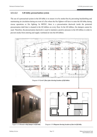
![Mechanical Ventilation System
Building Services
Lift lobby pressurisation system
Page 113 Malaysia International Trade
And Exhibition Centre
UBBL 1984
Part VII: Fire Requirements
[Section 150] Protected shafts
1) No protected shaft shall be constructed for use for any purposes additional to those specified
in this Part other than for the accomodation of any pipe or duct, or as sanitary
accommodation or washrooms, or both.
2) Subject to the provisions of this Part, any protected shaft should be completed enclosed.
There shall be no opening in any protecting structure other than any one or more of the following:
(d) If the protected shaft serves as, or contains a ventilating duct, an inlet to outlet from the duct or
an opening for the duct.
[Section 197] Protected lobbies
1. Protected lobbies shall be provided to serve staircases in buildings exceeding 18 metres
above ground level where the staircase enclosures are not ventilated through the external
walls
2. In buildings exceeding 45 metres above ground level, such protected lobbies shall be
pressurised to meet the requirements of Section 7 of the Australian Standard 1668, Part
1-1974 or any other system meeting the functional requirement of the D.G.F.S
3. Protected lobbies may be omitted the staircase enclosures are pressurized to meet the
requirements of by-law 200.
Summary :
The lift lobby pressurization system in MITEC meets the requirement stated in UBBL 1984 under section 150
and section 197. The protected lift lobby is pressurized to ease fire-fighting operation to be carried out during the
case of emergency.
(Uniform Building By-Law, 2006, pp. 57, 71) (Original work published in 1984)](https://image.slidesharecdn.com/finalisedb-190727174357/85/MITEC-Building-Service-System-126-320.jpg)
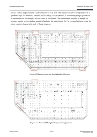
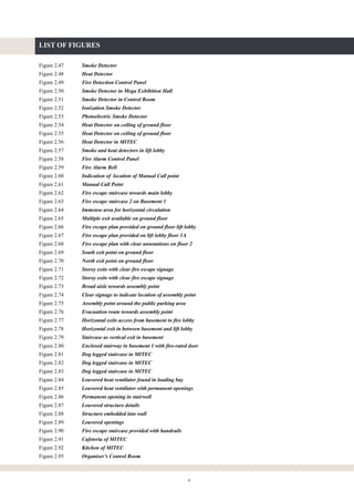
![Mechanical Ventilation System
Building Services
Basement car park exhaust system
Page 116 Malaysia International Trade
And Exhibition Centre
UBBL 1984
Part VIII: Fire Alarms, Fire Detection, Fire Extinguishment and Fire Fighting Access
[ Section 249 ] Smoke and heat venting
In windowless buildings, underground structures and large factories, smoking venting facilities shall
be provided for the safe use of exit.
Third schedule
7- Mechanical ventilation systems in basement areas
(1) Basement and other enclosures below ground level used for working areas or for occupancy
of more than two hours duration shall be provided with mechanical ventilation having a
minimum of six air changes per hour.
(2) Basement or underground car parks shall be provided with mechanical ventilation such that
the air exhausted to the external atmosphere should be constitute not less than six air
changes per hours. AIr extract opening shall be arranged such that it is not less than 0.5
metres above the floor level period system.
(3) Basement and other enclosures below ground level used for working areas or for occupancy
of more than two hours duration shall be provided with a minimum of one fresh air change
per hour, or the minimum of 0.28mm per person working in such area.
(Uniform Building By-Law, 2006, pp. 87) (Original work published in 1984)
Figure 4.36 Induced jet fan found in the basement car park Figure 4.37 Ductwork in the basement carpark](https://image.slidesharecdn.com/finalisedb-190727174357/85/MITEC-Building-Service-System-129-320.jpg)
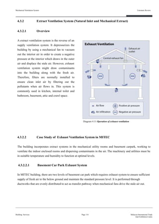
![UBBL 1984
Part VIII: Fire Alarms, Fire Detection, Fire Extinguishment and Fire Fighting Access
[ Section 249 ] Smoke and heat venting
In windowless buildings, underground structures and large factories, smoking venting facilities shall
be provided for the safe use of exit.
[ Section 250 ] Natural draught smoke ventilation
(1) Natural draught smoke venting shall utilize roof vents or vents in walls at or near the ceiling
level.
(2) Such vents shall normally be in open positions of they are closed they shall be so designed
to open automatically by an approved means in the events of a fire.
[ Section 251 ] Smoke vents to be adequate to prevent dangerous accumulation of smoke.
When smoke venting facilities are installed for purposes of exit safety in accordance with the
requirements of this Part they shall be adequate to prevent dangerous accumulation of smoke during
the period of time necessary to evacuate the area served using available exit facilities with a margin
of safety to allow for unforeseen contingencies.
Mechanical Ventilation System
Building Services
Lift motor room extract system
Page 119 Malaysia International Trade
And Exhibition Centre
Summary:
MITEC complies by the UBBL 1984 requirements for its ventilation system in aiding and providing regulated
air in concern for property damage as well as occupant safety. The ventilation concludes the requirement of the
section of 249, section 250 and section 251 as regards to the diagrams and figures above stating as the basement
carpark is fitted with necessity of an exhaust system to extract and disperse smoke, and harmful air particles
during a fire emergency.
(Uniform Building By-Law, 2006, pp. 87) (Original work published in 1984)](https://image.slidesharecdn.com/finalisedb-190727174357/85/MITEC-Building-Service-System-132-320.jpg)
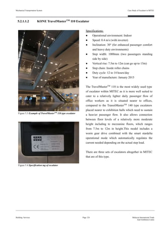
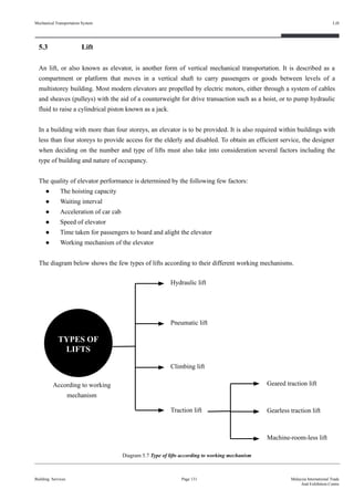
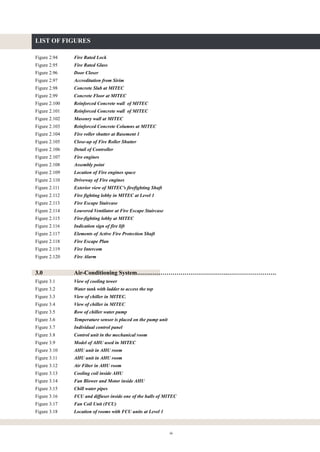
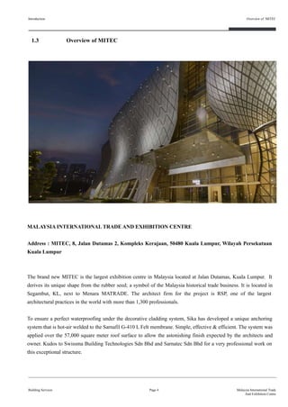
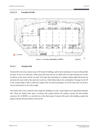
![5.3.1 Case Study of Lifts in MITEC
5.3.1.1 Overview
There are ten locations in MITEC where lifts can be found, summing up to 17 lifts altogether, of which 15 are
passenger lifts and two are freight lifts. Even though the building only has three main superstructure levels,
another three mezzanine floors for each level and two basement levels, the amount of lifts are necessary to
respond to the nature of the building as an international exhibition centre that needs to accommodate huge
numbers of visitors almost daily, and also to ensure sufficient circulation points are provided within the large
building.
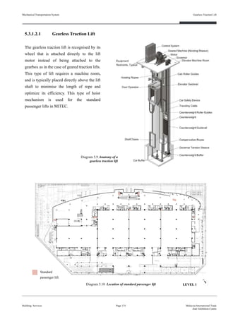
5.3.1.1.1 Passenger Lift
There are two different models of passengers lift in MITEC. The first type is the commonly seen lift that is
embedded into the walls of the building, whereas the second type is a see-through glass lift that is also
considered the centrepiece of the building.
● Type of elevator: Gearless traction elevator
● Brand: KONE
● Registered number: WP PMA 24034
● Capacity of person: 24 person
● Capacity of kilogram: 1576kg
● Rated speed: 1.0 - 1.75 m/s
● Car Height: 2400mm
● Entrance Opening: 1500x2100mm
● Type of entrance: 2-panel central opening
Building Services
Case Study of Lifts in MITEC
Page 132 Malaysia International Trade
And Exhibition Centre
UBBL 1984
Part VI: Construction Requirements
[ Section 124 ] Lifts
For non-residential buildings exceeding 4 storeys above or below the main access level at least one
lift shall be provided.
Figure 5.16 Passenger lift and fire lift placed together
(Uniform Building By-Law, 2006, pp. 43) (Original work published in 1984)
Mechanical Transportation System](https://image.slidesharecdn.com/finalisedb-190727174357/85/MITEC-Building-Service-System-145-320.jpg)
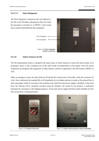
![Building Services Page 150 Malaysia International Trade
And Exhibition Centre
UBBL 1984
Part VII: Fire Requirements
[ Section 153 ] Smoke detectors for lift lobbies
(1) All lift lobbies shall be provided with smoke detectors.
[ Section 154 ] Emergency mode of operation in event of main power failure
(1) On failure of main power lifts shall return in sequence directly to the designated floor,
commencing with the fire lifts, without answering any car or landing calls and park with
doors open.
[ Section 155 ] Fire mode of operation
(2) If main power is available all lifts shall return in sequence directly to the designated floor,
commencing with the fire lifts, without answering any car or landing calls, overriding the
emergency stop button inside the car, but not any other emergency or safety devices, and
park with doors open.
(3) The fire lifts shall be available for use by the fire brigade on operation of the fireman’s
switch.
(4) Under this mode of operation, the fire lifts shall only operate in response to car calls but not
to landing calls in a mode of operation in accordance with by-law 154.
Part VIII: Fire Alarms, Fire Detection, Fire Extinguishment and Fire Fighting Access
[ Section 229 ] Means of access and fire fighting in buildings over 18.3 metres high
(5) A fire lift shall be provided to give access to each fire fighting access lobby or in the
absence of a lobby to the fire fighting staircase at each floor level.
(Uniform Building By-Law, 2006, pp. 58, 83) (Original work published in 1984)
Mechanical Transportation System Safety Features of Lift](https://image.slidesharecdn.com/finalisedb-190727174357/85/MITEC-Building-Service-System-163-320.jpg)
![4. VRF or VRV ? Learn About The Differences And VRF System Design. (n.d.). Retrieved from
https://coolautomation.com/wiki/vrv-or-vrf/
5. Khemani, H. (2018, November 12). Chilled Water Central Air Conditioning Plants. Retrieved from
https://www.brighthubengineering.com/hvac/50160-chilled-water-central-air-conditioning-systems/
6. Suvo. (2018, November 12). Understanding Central Air Conditioning and Heating Systems. Retrieved
from
https://www.brighthubengineering.com/hvac/104486-working-with-central-air-conditioning-and-heat-pu
mps/
7. Chilled Water System Basics [HVAC Commercial Cooling]. (2019, May 09). Retrieved from
https://highperformancehvac.com/chilled-water-system-basics/
8. How Air Conditioners Work. (2011, June 28). Retrieved from https://home.howstuffworks.com/ac4.htm
9. Chilled Water Air Conditioning Principles And Applications. (n.d.). Retrieved from
https://www.airconditioning-systems.com/chilled-water-air-conditioning.html
10. Thermal Care, Inc. (n.d.). Thermal Care, Inc. Retrieved from
https://www.thermalcare.com/how-does-a-chiller-work/
11. Air Handling Unit. (n.d.). Retrieved from
https://www.airconditioning-systems.com/air-handling-unit.html
12. Ravti, & Ravti. (2016, September 10). Equipment - Air Handling Units (AHU). Retrieved from
https://blog.ravti.com/equipment-air-handling-units-ahu-4900e8b85f83
13. Functions of An Air Handling Unit And Its Components. (n.d.). Retrieved from
http://www.mynewsdesk.com/in/pressreleases/functions-of-an-air-handling-unit-and-its-components-71
8365
14. Evans, P. (2019, May 20). How Air Handling Units work. Retrieved from
https://theengineeringmindset.com/air-handling-units-explained/
15. Fan Coil Unit Systems. (n.d.). Retrieved from :
https://www.betterbuildingspartnership.com.au/information/fan-coil-unit-systems/
16. What's a Split Air Conditioner? | Split vs Packaged AC Units. (2018, June 17). Retrieved from
https://asm-air.com/airconditioning/what-is-a-split-air-conditioner/
17. Khemani, H. (2018, November 12). Parts of Split Air Conditioners: Outdoor Unit. Retrieved from
https://www.brighthubengineering.com/hvac/45044-parts-of-the-split-air-condioners-outdoor-unit/
18. Khemani, H. (2018, November 12). Types of Air Conditioning Systems: Window, Split, Packaged and
Central. Retrieved from
https://www.brighthubengineering.com/hvac/897-types-of-air-conditioning-systems/
19. What is a Split Air Conditioner System? (n.d.). Retrieved from :
https://www.networx.com/article/split-air-conditioner-system
Mechanical Ventilation System
1. Introduction to Mechanical Fans. (2017, June 16). Retrieved May 15, 2019, from
https://www.mechlectures.com/mechanical-fans
Reference
Building Services Page 158 Malaysia International Trade
And Exhibition Centre](https://image.slidesharecdn.com/finalisedb-190727174357/85/MITEC-Building-Service-System-171-320.jpg)
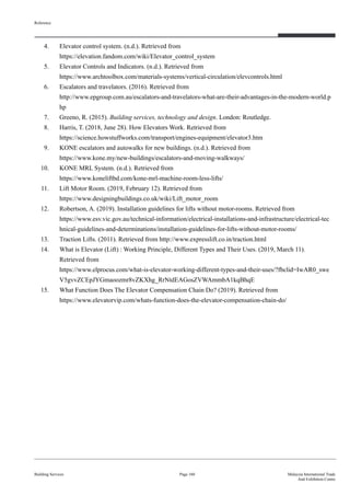

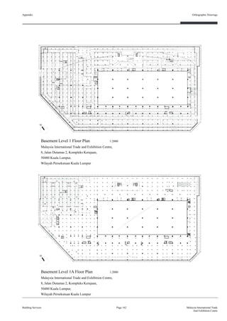
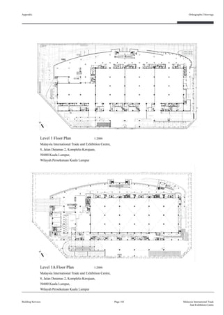
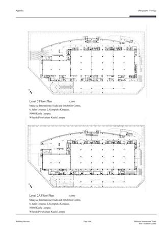
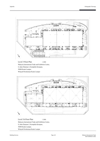
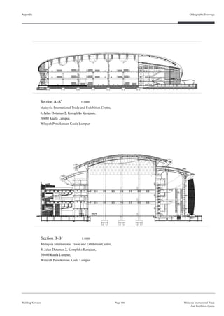
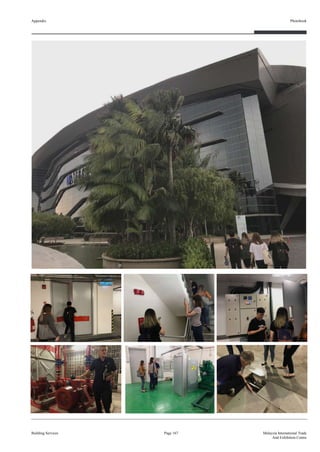
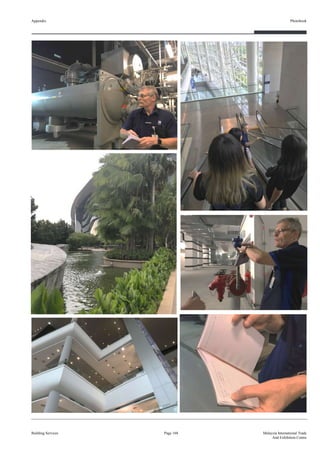


![제 23회 보아즈(BOAZ) 빅데이터 컨퍼런스 - [MBOAX] : ABSA를 활용한 소비자 반응 분석 기반 운영 효율화 대시보드 설계](https://cdn.slidesharecdn.com/ss_thumbnails/3-1boaz23rdconferencemboax-260203102709-9d519923-thumbnail.jpg?width=640&height=640&fit=bounds)


