Downloaded 170 times

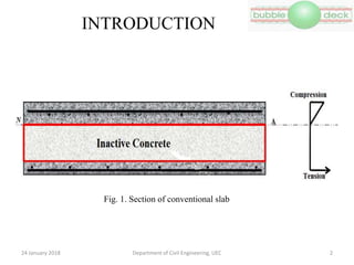

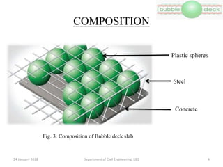
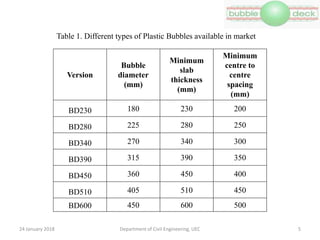

The document discusses the bubble-deck slab system, which uses high-density polyethylene hollow spheres to reduce the structural dead weight of slabs. It outlines the advantages of the system, such as increased strength, ease of installation, environmental benefits, and cost savings, along with the installation process and structural properties. Additionally, it highlights various applications and limitations, signaling a future scope for use in larger constructions like skyscrapers and auditoriums.


![[Deck] What's New in Spark-Iceberg Integration via DSV2.pptx](https://cdn.slidesharecdn.com/ss_thumbnails/deckwhatsnewinspark-icebergintegrationviadsv2-260210005337-25955b12-thumbnail.jpg?width=640&height=640&fit=bounds)


