SlideShare a Scribd company logo
1 of 5
Download to read offline
By Liam Botting Posted January 31, 2018 In News
WHY IS THE FORCE IN AN ANGLED SLING GREATER?
Why is the force in an angled sling greater has been a question I have been asked a number of times. As a result, and after an overlong
absence as a result of a busy holiday season at Britlift, we are finally back with a new article. I am very thankful for the feedback and
responses that I receive regarding these pieces, which often give me ideas for new articles. Today I will be answering a question that I
received after one of my previous articles.
As always, I will be aiming to explain the answers to these questions using common terminology and putting the explanations in a way
that I hope is accessible to all. This is not an article written specifically for design engineers and as such I have purposefully avoided
over technical language.
This time we are looking at a question I received from a LinkedIn connection:
Why are the forces greater when a sling is at an angle?
He knew the rigging rules of thumb to account for angled slings, but was after an explanation that didn’t just give him how, but also
gave him why.
I have expressed his question as the problem below and included a diagram to make things clearer:
Figure 1.
We use cookies to ensure that we give you the best experience on our website. Please click the accept button to continue. Please check the Privacy Policy here.
ACCEPT
Question: Load A has a central centre of gravity and weighs 10 tonnes. If B and C show the intended angle of connection to a pair
shackles used for lifting the load, why are 6.5t shackles/slings (combined capacity 13 tonnes) not suitable for lifting the load?
Break It Down:
To understand this problem, let us first just look at one side of the load. Take a look at the below section of the diagram from figure 1.
Figure 2.
We use cookies to ensure that we give you the best experience on our website. Please click the accept button to continue. Please check the Privacy Policy here.
ACCEPT
In figure 2, a wire rope sling is shown connected to a lifting point (or lug) via a shackle. The sling is connected at an angle of 50
degrees. The blue arrow shows the pull from the lifting device and the orange arrows show the resulting forces in the load.
The magnitudes (sizes) of the forces represented by the orange arrows are dependent upon the force represented by the blue arrow
(the pulling force on the sling). They are the horizontal and vertical components of the blue arrow and the stronger the pull on the sling,
the larger both of these forces will get.
Unless the orange arrows (forces passing into the load) are resisted, the load will move in that direction.
Let’s first consider the vertical orange arrow, this force wants to pull the load upwards and lift it from the ground. Obviously, the
resistance to this force is gravity acting upon the mass of the load itself. Should the pull in the sling be sufficient, the vertical force will
equal the opposing force created by gravity and the mass of the load – and the load will be lifted into the air.
The force in the horizontal orange arrow is created because the sling connection has been made at an angle, in this case 50 degrees.
The closer this angle gets to 0 degrees, the larger the force in this arrow will be. Just like the vertical arrow, this force must be resisted or
movement will occur.
Let’s view the whole diagram with the inclusion of some more force arrows.
Figure 3.
We use cookies to ensure that we give you the best experience on our website. Please click the accept button to continue. Please check the Privacy Policy here.
ACCEPT
Now in the full diagram (figure 3), we can see that the force represented by the horizontal orange arrow is resisted by the same force
created at the other end of the load. The balance of these forces is crucial to the stability of the load when it is in the air.
For this example, let’s assume the centre of gravity (CoG) is central and the horizontal forces are equal, this means that no horizontal
motion should occur. Although the load is now horizontally stable the load itself is now being pushed from each end and is thus in
compression (a crushing force). Many loads will have sufficient strength to deal with this compression but some will not, this is
traditionally where a spreader beam or lifting beam would be used.
As figure 2 represents just one of the two lugs shown in figure 3, the vertical force will be equal to half of the total mass of the load –
10/2 = 5 tonnes (the split of weight is 50/50 because the CoG was specified as central).
For the load to be lifted the vertical orange arrow needs to be at least 5 tonnes, because the blue arrow is responsible for both of the
orange arrows, the force in the sling (blue arrow) will always be more than 5 tonnes.
So we know the force in the sling is more than 5 tonnes, but is it more than 6.5 tonnes (the capacity of the shackle and sling mentioned
in the question)?
To work out the force in the sling riggers often use a factor method whereby they multiply the force by a certain number which
depends upon the angle of the sling. This is actually a simplification of the same method that rigging engineers use (trigonometry).
Remember sin, cos and tan? Trigonometry, which is something that most of us learned at age 13/14, is used every day by engineers to
solve problems just like this. Understandably, most adults won’t remember how to do these calculations (and won’t want to!), but
fortunately there is another way to answer the question.
The Answer:
Trigonometry is a branch of mathematics which covers triangles and the relationships between their lengths and angles. Believe it or
not the problem we have in the question can actually be solved by drawing a triangle. This is because the relationship between the
size of the vertical force, the horizontal force and the angled force (orange and blue arrows in figure 3), is the same as the relationship
between the lengths of the sides on a right-angled triangle.
Take a look at the triangle drawn in figure 4.
Figure 4.
We use cookies to ensure that we give you the best experience on our website. Please click the accept button to continue. Please check the Privacy Policy here.
ACCEPT
In figure 4, side A is representative of the vertical force (vertical orange arrow in figure 2), side B is representative of the horizontal force
(horizontal orange arrow in figure 2) and side C is representative of the angled force in the sling (blue arrow in figure 2).
Using the grid in the background of figure 4, you can see that Side A is 5 grid squares long, this represents the 5 tonnes of vertical force.
The 50° angle in the bottom right of the triangle is the same as the 50° angle of the sling in figure 2.
The angle between the orange arrows (horizontal and vertical forces) will is 90° and as all angles of a triangle add up to 180°, the final
angle between sides C and A is 40°. These angles along with the length of side A allow the whole triangle to be drawn.
To draw this triangle, I drew side A first at a length of 5, and then drew out sides B and C from each end of side A until they met.
Now that the triangle is complete, the length of side C can be measured, the length of this side is the force in the angled sling (blue
arrow) from figure 2.
If you were to scale the diagram in figure 4 using the grid and check the length of side C, you would find that the length of side C is
6.527. This means the force in the angled sling is 6.527 tonnes, so to answer the question, No, a 6.5t shackle (or sling) would not be
suitable for this lift because the angled load is greater than 6.5 tonnes.
Although this answers the question, there is still more information that the triangle can give us. Side B is representative of the horizontal
force which is the compressive force in the load. Side B measures 4.1955 which can be approximately checked by counting the grid
squares in figure 4. This force in itself does not create compression in the load on its own, we need an opposing force. The forces going
through the other lug in this example create an equal opposing force which means there is 4.1955 tonnes of compression in the load. A
common mistake here is assuming the compression is doubled because there is a force from both ends – which is not the case.
Calculating the compression like this is important for structural engineers when they are checking the safety of a load to be lifted, as
well as rigging engineers designing lifting equipment such as a spreader beam.
There are other methods to work out the length of the sides in the triangles, which, once you are familiar with the mathematics, are
much quicker than drawing a triangle every time, but the principles remain the same.
I hope this article has been of interest, any questions or anything you feel you can add to this article, then please leave a comment
below, email sales@britlift.com or message me on Linkedin.
Thanks for reading and if you would like to stay up to date as these articles come out then please follow Britlift on Linkedin.
Anthony Culshaw
Anthony is currently the Technical Director at Britlift (www.britlift.com), designers and manufacturers of lifting beams, spreader beams
and custom below the hook frames. He is a former member of the LEEA Technical Committee and has spoken at lifting conferences
around the world on the subject of below the hook lifting equipment. For more information on Britlift and their design and
manufacture capabilities, please visit www.britlift.com.
LIFTING BEAMS, SPREADER BEAMS, SPREADER FRAMES
CLICK ON THE BELOW LINK TO VIEW BRITLIFT PRODUCTS AND SERVICES
As a specilist manufacture of below the hook lifting equipment based in the UK, Britlift offer a huge variety of lifting beam, lifting
frame, spreader beam and spreader frame options and services.
View our PRODUCTS page.
We use cookies to ensure that we give you the best experience on our website. Please click the accept button to continue. Please check the Privacy Policy here.
ACCEPT

More Related Content

Similar to britlift_spreader vs beam.pdf

8 ja drag methodius
8 ja drag methodius8 ja drag methodius
8 ja drag methodius
FDonkor
 
B Ending Moments And Shearing Forces In Beams2
B Ending Moments And Shearing Forces In Beams2B Ending Moments And Shearing Forces In Beams2
B Ending Moments And Shearing Forces In Beams2
Amr Hamed
 
B Ending Moments And Shearing Forces In Beams2
B Ending Moments And Shearing Forces In Beams2B Ending Moments And Shearing Forces In Beams2
B Ending Moments And Shearing Forces In Beams2
Amr Hamed
 
Bendingmomentsandshearingforcesinbeams2 100114165451-phpapp01
Bendingmomentsandshearingforcesinbeams2 100114165451-phpapp01Bendingmomentsandshearingforcesinbeams2 100114165451-phpapp01
Bendingmomentsandshearingforcesinbeams2 100114165451-phpapp01
Aero Mohamed
 

Similar to britlift_spreader vs beam.pdf (20)

Steel strucure lec # (6)
Steel strucure lec #  (6)Steel strucure lec #  (6)
Steel strucure lec # (6)
 
Mm210(6b)
Mm210(6b)Mm210(6b)
Mm210(6b)
 
Ch 9 Rotational Dynamics
Ch 9 Rotational DynamicsCh 9 Rotational Dynamics
Ch 9 Rotational Dynamics
 
module 3 (Mechanics)
module 3 (Mechanics)module 3 (Mechanics)
module 3 (Mechanics)
 
Ch05 circular motion 5 02 2015(2)
Ch05 circular motion 5 02 2015(2)Ch05 circular motion 5 02 2015(2)
Ch05 circular motion 5 02 2015(2)
 
8 ja drag methodius
8 ja drag methodius8 ja drag methodius
8 ja drag methodius
 
Chapter 5: Axial Force, Shear, and Bending Moment
Chapter 5: Axial Force, Shear, and Bending MomentChapter 5: Axial Force, Shear, and Bending Moment
Chapter 5: Axial Force, Shear, and Bending Moment
 
Chapter 1 - rotational dnamics excercises solution
Chapter 1 - rotational dnamics excercises solutionChapter 1 - rotational dnamics excercises solution
Chapter 1 - rotational dnamics excercises solution
 
Bcon report final
Bcon report finalBcon report final
Bcon report final
 
Bcon report final
Bcon report finalBcon report final
Bcon report final
 
Bcon report final
Bcon report finalBcon report final
Bcon report final
 
Investigating The Lever V1 6 Formatted
Investigating The  Lever V1 6 FormattedInvestigating The  Lever V1 6 Formatted
Investigating The Lever V1 6 Formatted
 
B Ending Moments And Shearing Forces In Beams2
B Ending Moments And Shearing Forces In Beams2B Ending Moments And Shearing Forces In Beams2
B Ending Moments And Shearing Forces In Beams2
 
B Ending Moments And Shearing Forces In Beams2
B Ending Moments And Shearing Forces In Beams2B Ending Moments And Shearing Forces In Beams2
B Ending Moments And Shearing Forces In Beams2
 
Shear and Bending Moment in Beams
Shear and Bending Moment in BeamsShear and Bending Moment in Beams
Shear and Bending Moment in Beams
 
Bendingmomentsandshearingforcesinbeams2 100114165451-phpapp01
Bendingmomentsandshearingforcesinbeams2 100114165451-phpapp01Bendingmomentsandshearingforcesinbeams2 100114165451-phpapp01
Bendingmomentsandshearingforcesinbeams2 100114165451-phpapp01
 
Shear force and bending moment
Shear force and bending momentShear force and bending moment
Shear force and bending moment
 
Congr similar
Congr similarCongr similar
Congr similar
 
Cape physics unit 1st edition
Cape physics  unit 1st editionCape physics  unit 1st edition
Cape physics unit 1st edition
 
.
..
.
 

Recently uploaded

Personalisation of Education by AI and Big Data - Lourdes Guàrdia
Personalisation of Education by AI and Big Data - Lourdes GuàrdiaPersonalisation of Education by AI and Big Data - Lourdes Guàrdia
Personalisation of Education by AI and Big Data - Lourdes Guàrdia
EADTU
 
會考英文會考英文會考英文會考英文會考英文會考英文會考英文會考英文會考英文會考英文會考英文
會考英文會考英文會考英文會考英文會考英文會考英文會考英文會考英文會考英文會考英文會考英文會考英文會考英文會考英文會考英文會考英文會考英文會考英文會考英文會考英文會考英文會考英文
會考英文會考英文會考英文會考英文會考英文會考英文會考英文會考英文會考英文會考英文會考英文
中 央社
 
會考英聽會考英聽會考英聽會考英聽會考英聽會考英聽會考英聽會考英聽會考英聽會考英聽
會考英聽會考英聽會考英聽會考英聽會考英聽會考英聽會考英聽會考英聽會考英聽會考英聽會考英聽會考英聽會考英聽會考英聽會考英聽會考英聽會考英聽會考英聽會考英聽會考英聽
會考英聽會考英聽會考英聽會考英聽會考英聽會考英聽會考英聽會考英聽會考英聽會考英聽
中 央社
 
Spellings Wk 4 and Wk 5 for Grade 4 at CAPS
Spellings Wk 4 and Wk 5 for Grade 4 at CAPSSpellings Wk 4 and Wk 5 for Grade 4 at CAPS
Spellings Wk 4 and Wk 5 for Grade 4 at CAPS
AnaAcapella
 

Recently uploaded (20)

Basic Civil Engineering notes on Transportation Engineering & Modes of Transport
Basic Civil Engineering notes on Transportation Engineering & Modes of TransportBasic Civil Engineering notes on Transportation Engineering & Modes of Transport
Basic Civil Engineering notes on Transportation Engineering & Modes of Transport
 
Improved Approval Flow in Odoo 17 Studio App
Improved Approval Flow in Odoo 17 Studio AppImproved Approval Flow in Odoo 17 Studio App
Improved Approval Flow in Odoo 17 Studio App
 
Personalisation of Education by AI and Big Data - Lourdes Guàrdia
Personalisation of Education by AI and Big Data - Lourdes GuàrdiaPersonalisation of Education by AI and Big Data - Lourdes Guàrdia
Personalisation of Education by AI and Big Data - Lourdes Guàrdia
 
An overview of the various scriptures in Hinduism
An overview of the various scriptures in HinduismAn overview of the various scriptures in Hinduism
An overview of the various scriptures in Hinduism
 
會考英文會考英文會考英文會考英文會考英文會考英文會考英文會考英文會考英文會考英文會考英文
會考英文會考英文會考英文會考英文會考英文會考英文會考英文會考英文會考英文會考英文會考英文會考英文會考英文會考英文會考英文會考英文會考英文會考英文會考英文會考英文會考英文會考英文
會考英文會考英文會考英文會考英文會考英文會考英文會考英文會考英文會考英文會考英文會考英文
 
ĐỀ THAM KHẢO KÌ THI TUYỂN SINH VÀO LỚP 10 MÔN TIẾNG ANH FORM 50 CÂU TRẮC NGHI...
ĐỀ THAM KHẢO KÌ THI TUYỂN SINH VÀO LỚP 10 MÔN TIẾNG ANH FORM 50 CÂU TRẮC NGHI...ĐỀ THAM KHẢO KÌ THI TUYỂN SINH VÀO LỚP 10 MÔN TIẾNG ANH FORM 50 CÂU TRẮC NGHI...
ĐỀ THAM KHẢO KÌ THI TUYỂN SINH VÀO LỚP 10 MÔN TIẾNG ANH FORM 50 CÂU TRẮC NGHI...
 
Mattingly "AI & Prompt Design: Named Entity Recognition"
Mattingly "AI & Prompt Design: Named Entity Recognition"Mattingly "AI & Prompt Design: Named Entity Recognition"
Mattingly "AI & Prompt Design: Named Entity Recognition"
 
Major project report on Tata Motors and its marketing strategies
Major project report on Tata Motors and its marketing strategiesMajor project report on Tata Motors and its marketing strategies
Major project report on Tata Motors and its marketing strategies
 
會考英聽會考英聽會考英聽會考英聽會考英聽會考英聽會考英聽會考英聽會考英聽會考英聽
會考英聽會考英聽會考英聽會考英聽會考英聽會考英聽會考英聽會考英聽會考英聽會考英聽會考英聽會考英聽會考英聽會考英聽會考英聽會考英聽會考英聽會考英聽會考英聽會考英聽
會考英聽會考英聽會考英聽會考英聽會考英聽會考英聽會考英聽會考英聽會考英聽會考英聽
 
DEMONSTRATION LESSON IN ENGLISH 4 MATATAG CURRICULUM
DEMONSTRATION LESSON IN ENGLISH 4 MATATAG CURRICULUMDEMONSTRATION LESSON IN ENGLISH 4 MATATAG CURRICULUM
DEMONSTRATION LESSON IN ENGLISH 4 MATATAG CURRICULUM
 
Supporting Newcomer Multilingual Learners
Supporting Newcomer  Multilingual LearnersSupporting Newcomer  Multilingual Learners
Supporting Newcomer Multilingual Learners
 
Andreas Schleicher presents at the launch of What does child empowerment mean...
Andreas Schleicher presents at the launch of What does child empowerment mean...Andreas Schleicher presents at the launch of What does child empowerment mean...
Andreas Schleicher presents at the launch of What does child empowerment mean...
 
Including Mental Health Support in Project Delivery, 14 May.pdf
Including Mental Health Support in Project Delivery, 14 May.pdfIncluding Mental Health Support in Project Delivery, 14 May.pdf
Including Mental Health Support in Project Delivery, 14 May.pdf
 
Spring gala 2024 photo slideshow - Celebrating School-Community Partnerships
Spring gala 2024 photo slideshow - Celebrating School-Community PartnershipsSpring gala 2024 photo slideshow - Celebrating School-Community Partnerships
Spring gala 2024 photo slideshow - Celebrating School-Community Partnerships
 
Spellings Wk 4 and Wk 5 for Grade 4 at CAPS
Spellings Wk 4 and Wk 5 for Grade 4 at CAPSSpellings Wk 4 and Wk 5 for Grade 4 at CAPS
Spellings Wk 4 and Wk 5 for Grade 4 at CAPS
 
Stl Algorithms in C++ jjjjjjjjjjjjjjjjjj
Stl Algorithms in C++ jjjjjjjjjjjjjjjjjjStl Algorithms in C++ jjjjjjjjjjjjjjjjjj
Stl Algorithms in C++ jjjjjjjjjjjjjjjjjj
 
TỔNG HỢP HƠN 100 ĐỀ THI THỬ TỐT NGHIỆP THPT TOÁN 2024 - TỪ CÁC TRƯỜNG, TRƯỜNG...
TỔNG HỢP HƠN 100 ĐỀ THI THỬ TỐT NGHIỆP THPT TOÁN 2024 - TỪ CÁC TRƯỜNG, TRƯỜNG...TỔNG HỢP HƠN 100 ĐỀ THI THỬ TỐT NGHIỆP THPT TOÁN 2024 - TỪ CÁC TRƯỜNG, TRƯỜNG...
TỔNG HỢP HƠN 100 ĐỀ THI THỬ TỐT NGHIỆP THPT TOÁN 2024 - TỪ CÁC TRƯỜNG, TRƯỜNG...
 
UChicago CMSC 23320 - The Best Commit Messages of 2024
UChicago CMSC 23320 - The Best Commit Messages of 2024UChicago CMSC 23320 - The Best Commit Messages of 2024
UChicago CMSC 23320 - The Best Commit Messages of 2024
 
Graduate Outcomes Presentation Slides - English (v3).pptx
Graduate Outcomes Presentation Slides - English (v3).pptxGraduate Outcomes Presentation Slides - English (v3).pptx
Graduate Outcomes Presentation Slides - English (v3).pptx
 
diagnosting testing bsc 2nd sem.pptx....
diagnosting testing bsc 2nd sem.pptx....diagnosting testing bsc 2nd sem.pptx....
diagnosting testing bsc 2nd sem.pptx....
 

britlift_spreader vs beam.pdf

  • 1. By Liam Botting Posted January 31, 2018 In News WHY IS THE FORCE IN AN ANGLED SLING GREATER? Why is the force in an angled sling greater has been a question I have been asked a number of times. As a result, and after an overlong absence as a result of a busy holiday season at Britlift, we are finally back with a new article. I am very thankful for the feedback and responses that I receive regarding these pieces, which often give me ideas for new articles. Today I will be answering a question that I received after one of my previous articles. As always, I will be aiming to explain the answers to these questions using common terminology and putting the explanations in a way that I hope is accessible to all. This is not an article written specifically for design engineers and as such I have purposefully avoided over technical language. This time we are looking at a question I received from a LinkedIn connection: Why are the forces greater when a sling is at an angle? He knew the rigging rules of thumb to account for angled slings, but was after an explanation that didn’t just give him how, but also gave him why. I have expressed his question as the problem below and included a diagram to make things clearer: Figure 1. We use cookies to ensure that we give you the best experience on our website. Please click the accept button to continue. Please check the Privacy Policy here. ACCEPT
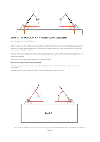
  • 2. Question: Load A has a central centre of gravity and weighs 10 tonnes. If B and C show the intended angle of connection to a pair shackles used for lifting the load, why are 6.5t shackles/slings (combined capacity 13 tonnes) not suitable for lifting the load? Break It Down: To understand this problem, let us first just look at one side of the load. Take a look at the below section of the diagram from figure 1. Figure 2. We use cookies to ensure that we give you the best experience on our website. Please click the accept button to continue. Please check the Privacy Policy here. ACCEPT
  • 3. In figure 2, a wire rope sling is shown connected to a lifting point (or lug) via a shackle. The sling is connected at an angle of 50 degrees. The blue arrow shows the pull from the lifting device and the orange arrows show the resulting forces in the load. The magnitudes (sizes) of the forces represented by the orange arrows are dependent upon the force represented by the blue arrow (the pulling force on the sling). They are the horizontal and vertical components of the blue arrow and the stronger the pull on the sling, the larger both of these forces will get. Unless the orange arrows (forces passing into the load) are resisted, the load will move in that direction. Let’s first consider the vertical orange arrow, this force wants to pull the load upwards and lift it from the ground. Obviously, the resistance to this force is gravity acting upon the mass of the load itself. Should the pull in the sling be sufficient, the vertical force will equal the opposing force created by gravity and the mass of the load – and the load will be lifted into the air. The force in the horizontal orange arrow is created because the sling connection has been made at an angle, in this case 50 degrees. The closer this angle gets to 0 degrees, the larger the force in this arrow will be. Just like the vertical arrow, this force must be resisted or movement will occur. Let’s view the whole diagram with the inclusion of some more force arrows. Figure 3. We use cookies to ensure that we give you the best experience on our website. Please click the accept button to continue. Please check the Privacy Policy here. ACCEPT
  • 4. Now in the full diagram (figure 3), we can see that the force represented by the horizontal orange arrow is resisted by the same force created at the other end of the load. The balance of these forces is crucial to the stability of the load when it is in the air. For this example, let’s assume the centre of gravity (CoG) is central and the horizontal forces are equal, this means that no horizontal motion should occur. Although the load is now horizontally stable the load itself is now being pushed from each end and is thus in compression (a crushing force). Many loads will have sufficient strength to deal with this compression but some will not, this is traditionally where a spreader beam or lifting beam would be used. As figure 2 represents just one of the two lugs shown in figure 3, the vertical force will be equal to half of the total mass of the load – 10/2 = 5 tonnes (the split of weight is 50/50 because the CoG was specified as central). For the load to be lifted the vertical orange arrow needs to be at least 5 tonnes, because the blue arrow is responsible for both of the orange arrows, the force in the sling (blue arrow) will always be more than 5 tonnes. So we know the force in the sling is more than 5 tonnes, but is it more than 6.5 tonnes (the capacity of the shackle and sling mentioned in the question)? To work out the force in the sling riggers often use a factor method whereby they multiply the force by a certain number which depends upon the angle of the sling. This is actually a simplification of the same method that rigging engineers use (trigonometry). Remember sin, cos and tan? Trigonometry, which is something that most of us learned at age 13/14, is used every day by engineers to solve problems just like this. Understandably, most adults won’t remember how to do these calculations (and won’t want to!), but fortunately there is another way to answer the question. The Answer: Trigonometry is a branch of mathematics which covers triangles and the relationships between their lengths and angles. Believe it or not the problem we have in the question can actually be solved by drawing a triangle. This is because the relationship between the size of the vertical force, the horizontal force and the angled force (orange and blue arrows in figure 3), is the same as the relationship between the lengths of the sides on a right-angled triangle. Take a look at the triangle drawn in figure 4. Figure 4. We use cookies to ensure that we give you the best experience on our website. Please click the accept button to continue. Please check the Privacy Policy here. ACCEPT
  • 5. In figure 4, side A is representative of the vertical force (vertical orange arrow in figure 2), side B is representative of the horizontal force (horizontal orange arrow in figure 2) and side C is representative of the angled force in the sling (blue arrow in figure 2). Using the grid in the background of figure 4, you can see that Side A is 5 grid squares long, this represents the 5 tonnes of vertical force. The 50° angle in the bottom right of the triangle is the same as the 50° angle of the sling in figure 2. The angle between the orange arrows (horizontal and vertical forces) will is 90° and as all angles of a triangle add up to 180°, the final angle between sides C and A is 40°. These angles along with the length of side A allow the whole triangle to be drawn. To draw this triangle, I drew side A first at a length of 5, and then drew out sides B and C from each end of side A until they met. Now that the triangle is complete, the length of side C can be measured, the length of this side is the force in the angled sling (blue arrow) from figure 2. If you were to scale the diagram in figure 4 using the grid and check the length of side C, you would find that the length of side C is 6.527. This means the force in the angled sling is 6.527 tonnes, so to answer the question, No, a 6.5t shackle (or sling) would not be suitable for this lift because the angled load is greater than 6.5 tonnes. Although this answers the question, there is still more information that the triangle can give us. Side B is representative of the horizontal force which is the compressive force in the load. Side B measures 4.1955 which can be approximately checked by counting the grid squares in figure 4. This force in itself does not create compression in the load on its own, we need an opposing force. The forces going through the other lug in this example create an equal opposing force which means there is 4.1955 tonnes of compression in the load. A common mistake here is assuming the compression is doubled because there is a force from both ends – which is not the case. Calculating the compression like this is important for structural engineers when they are checking the safety of a load to be lifted, as well as rigging engineers designing lifting equipment such as a spreader beam. There are other methods to work out the length of the sides in the triangles, which, once you are familiar with the mathematics, are much quicker than drawing a triangle every time, but the principles remain the same. I hope this article has been of interest, any questions or anything you feel you can add to this article, then please leave a comment below, email sales@britlift.com or message me on Linkedin. Thanks for reading and if you would like to stay up to date as these articles come out then please follow Britlift on Linkedin. Anthony Culshaw Anthony is currently the Technical Director at Britlift (www.britlift.com), designers and manufacturers of lifting beams, spreader beams and custom below the hook frames. He is a former member of the LEEA Technical Committee and has spoken at lifting conferences around the world on the subject of below the hook lifting equipment. For more information on Britlift and their design and manufacture capabilities, please visit www.britlift.com. LIFTING BEAMS, SPREADER BEAMS, SPREADER FRAMES CLICK ON THE BELOW LINK TO VIEW BRITLIFT PRODUCTS AND SERVICES As a specilist manufacture of below the hook lifting equipment based in the UK, Britlift offer a huge variety of lifting beam, lifting frame, spreader beam and spreader frame options and services. View our PRODUCTS page. We use cookies to ensure that we give you the best experience on our website. Please click the accept button to continue. Please check the Privacy Policy here. ACCEPT