Downloaded 450 times

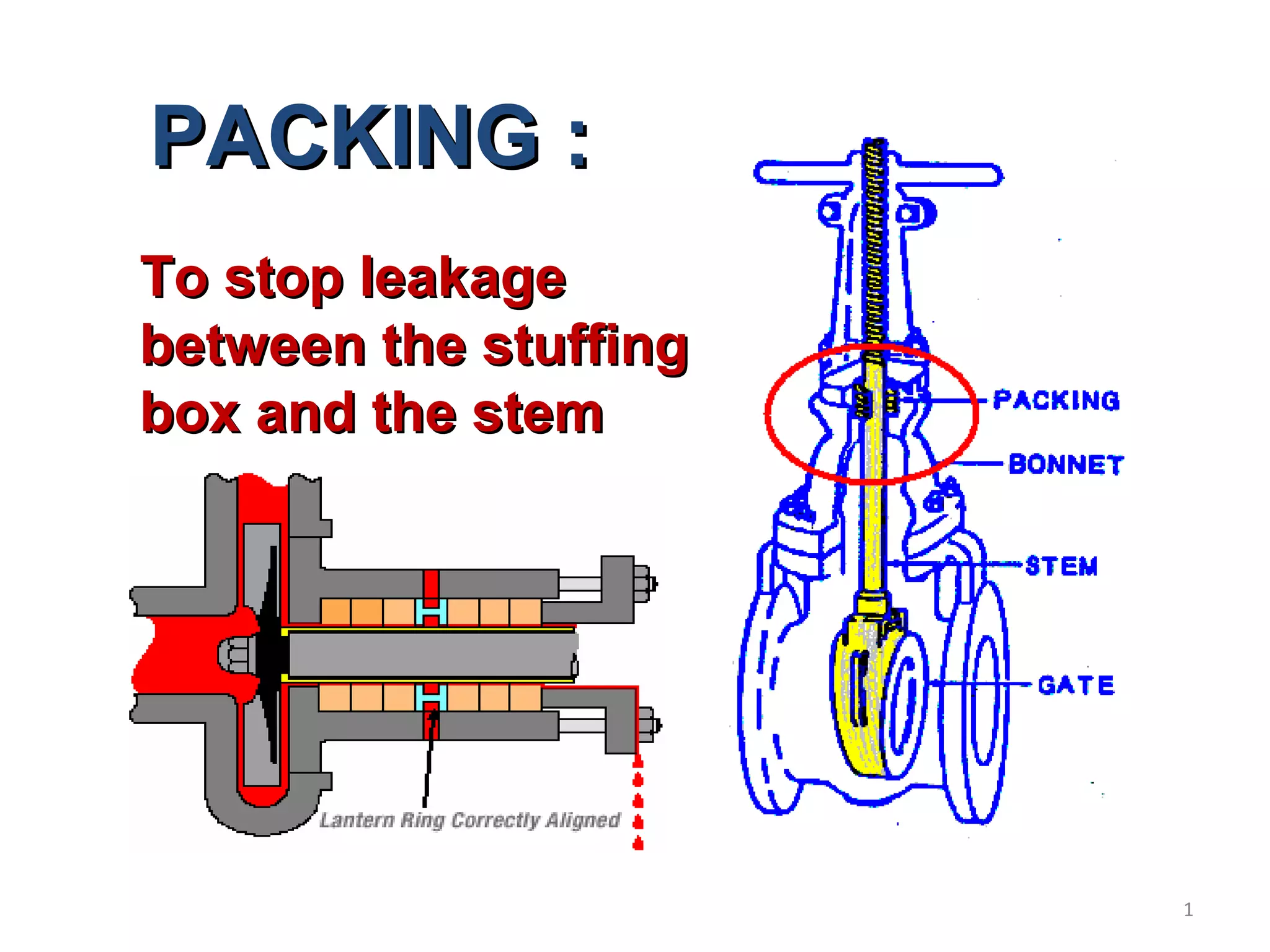
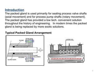
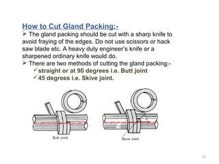
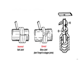
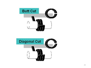

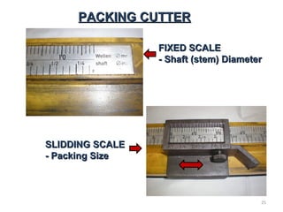


The document provides a comprehensive overview of gland packing used for sealing process valve shafts and pump shafts, highlighting its applications, maintenance requirements, and the properties needed for effective sealing. It discusses various packing materials and the importance of selecting the correct type based on fluid characteristics, with maintenance procedures outlined for replacing and installing gland packing. Additionally, it underscores the significance of using lantern rings for lubrication in complex applications and the best practices for handling and installing packing materials.


