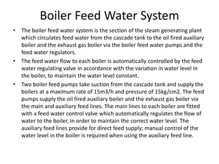
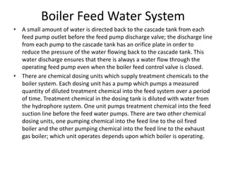
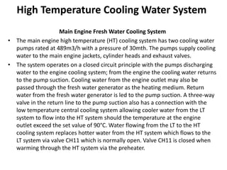
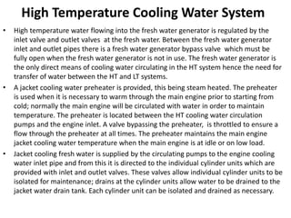
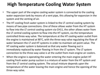
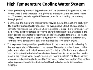
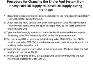
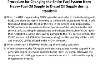
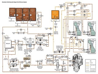
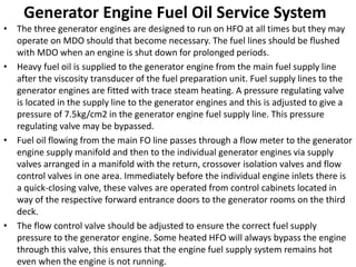
Download as PDF, PPTX


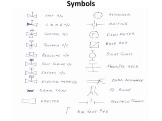
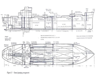
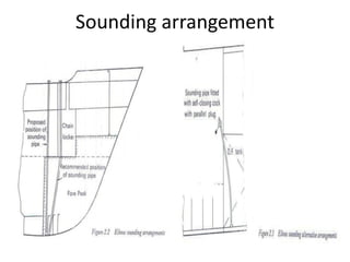
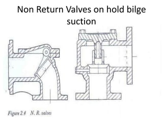
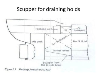
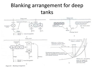
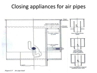
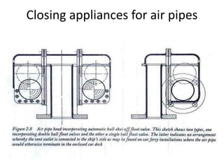
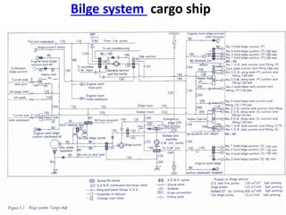
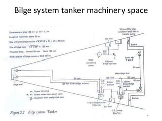
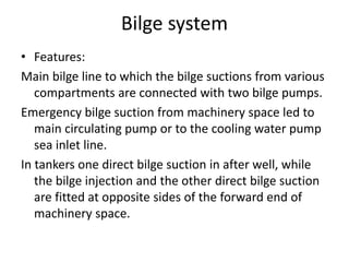
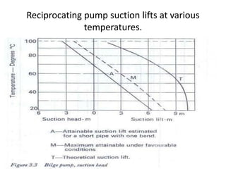
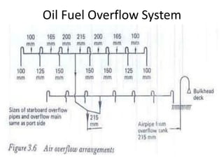
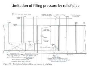
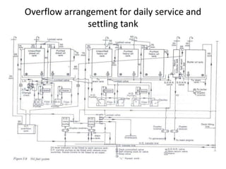
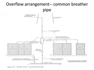
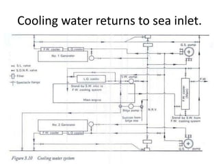
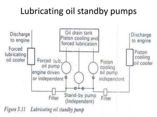
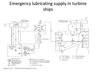
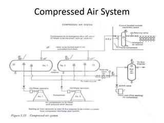
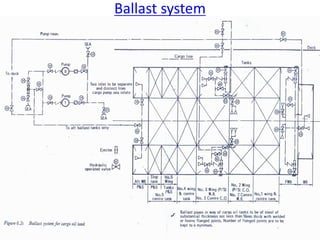
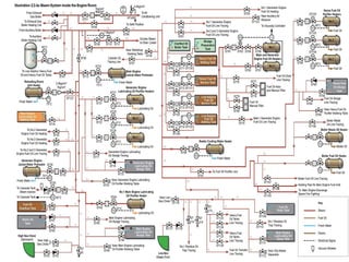
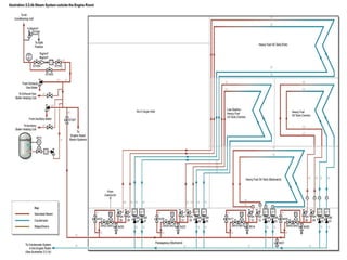
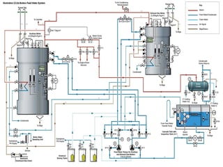
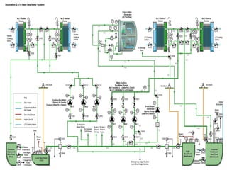
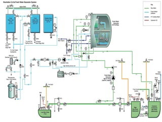
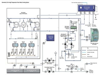
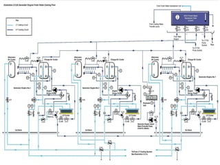
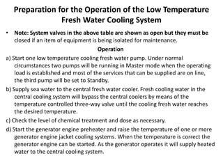
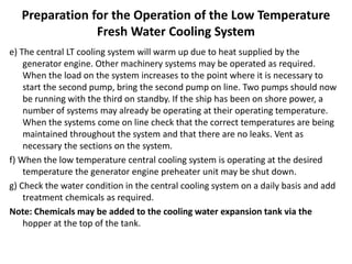
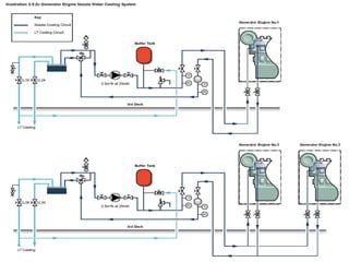
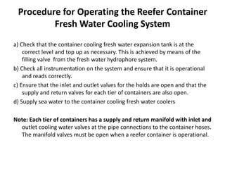
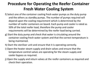
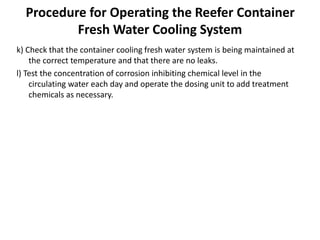
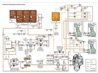

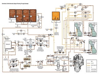
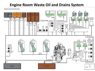

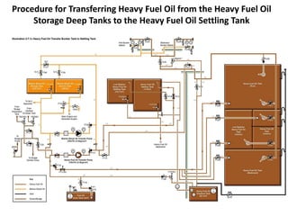
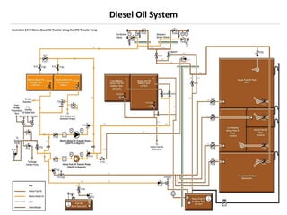

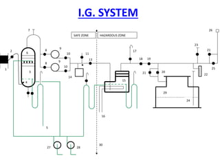
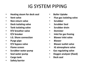
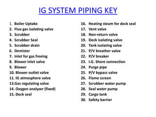
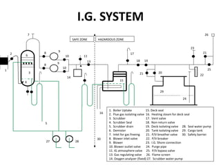

The document describes the piping systems on a ship. It discusses the importance of an efficient piping system and provides examples of common piping systems like bilge, ballast, fuel, cooling water, lubrication oil, compressed air, steam, and cargo tank systems. It emphasizes preparing accurate piping plans and diagrams using standardized symbols and labeling key details like pipe sizes, flow directions, and component capacities. Common arrangements for pumping, drainage, overflows, and other aspects of key systems are illustrated with diagrams.


