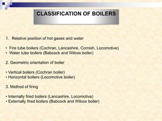
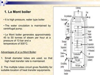
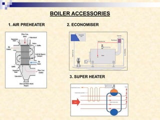
HIGH PRSSURE BOILERS
prepared by
Sneh Patel
Introduction
Classification of boilers
High Pressure Boilers
Boiler mountings and accessories
Feed water and Feed water Treatment Plant
Draught System
Design of Chimney
Boiler Heat Balance Sheet
INTRODUCTION
According to Indian Boiler Regulation (I.B.R) Act 2007,”Boiler is a closed pressure
vessel in which steam is generated with capacity exceeding 25 liters, gauge
pressure greater than or equal to 1 kg/cm2, and water is heated at 100oc or
above”
Steam boiler is a closed vessel in which heat produced by the combustion of fuel
is utilized to generate steam from water, at desired temperature and pressure
DEFINATION
APPLICATIONS OF BOILERS
1. Power generation
2. Heating
3. Industrial processes
1. Relative position of hot gases and water
• Fire tube boilers (Cochran, Lancashire, Cornish, Locomotive)
• Water tube boilers (Babcock and Wilcox boiler)
2. Geometric orientation of boiler
• Vertical boilers (Cochran boiler)
• Horizontal boilers (Locomotive boiler)
3. Method of firing
• Internally fired boilers (Lancashire, Locomotive)
• Externally fired boilers (Babcock and Wilcox boiler)
CLASSIFICATION OF BOILERS
4. Pressure of steam
• Low pressure boilers (<= 80 bars-Cochran, Lancashire, Cornish, Locomotive)
• High pressure boilers (>80 bars-Babcock and Wilcox boiler, Lamont boiler)
5. Method of circulation of water
• Natural circulation boilers (Lancashire, Locomotive, Babcock & Wilcox boilers)
• Forced circulation boilers (La-mont boiler, Velox boiler, Benson boiler)
6. Nature of service to be performed
• Land boilers ( Lancashire boiler)
• Mobile boilers (or) Portable boilers (Locomotive boiler)
7. Number of tubes in boiler
• Single tube boilers (Cornish boiler)
• Multi tube boilers (Locomotive, Cochran Babcock and Wilcox boiler)
HIGH PRESSURE BOILERS
A boiler is called a high pressure boiler when it operates with a steam pressure
above 80bar. The high-pressure boilers are widely used for power generation in
thermal power plants.
Example: Lamont boiler, Benson boiler, loeffler boiler, Babcock and Wilcox boiler
Features of High pressure Boilers
1. Forced circulation of water
2. Large number of small diameter tubes
3. Higher steam pressure and temperature
4. Improved mode of heat transfer and heating
5. Pressurized combustion
6. Compactness
7. High efficiency
8. Once through construction
1. La Mont boiler
• It is high pressure, water type boiler
• The water circulation is maintained by
centrifugal pump.
• La Mont boiler generates approximately
45 to 50 tonnes of steam per hour at a
pressure of 13 bar and a
temperature of 500°C.
Advantages of a La Mont Boiler:
1. Small diameter tubes are used, so that
high heat transfer rate is maintained.
2. The multiple tubes circuit gives flexibility for
suitable location of heat transfer equipments.
2. Benson boiler
• Difficulties of bubble formation is eliminated.
• The transport of Benson boiler parts is easy as
no drums are required and majority of the parts
are carried to the site without pre-assembly.
• Required smaller floor area.
• The superheater in the Benson boiler is an
integral part of forced circulation system
therefore no special starting arrangement for
superheater is required.
• It has very little storage capacity compared to
drum type boiler.
3. Loeffler boiler
• Difficulties of deposition of salt and sediment is
eliminated.
• Most of the steam is generated outside from
the feed water using part of the superheated
steam coming out from the boiler.
• Loeffler boilers with generating capacity of 94.5
tones/hr and operating at 140 bar have already
been commissioned.
4. Babcock and Wilcox boiler
• Babcock and Wilcox is a water-tube
boiler is an example of horizontal
inclined tube boiler it also a High
Pressure Boiler.
• The angle of inclination of the water
tubes to the horizontal is about 15°
or more.
• The pressure of steam in case of
cross drum boiler may be as high as
100 bar and steaming capacity up to
•27000 kg/h.
BOILER MOUNTINGS &
ACCESSORIES
Mainly mountings are required and essential to a Boiler :
1. Safety valve
2. Two water level indicators
3. Pressure gauge
4. Fusible plug
5. Steam stop valve
6. Feed check valve
7. Blow-of cock
8. Man and mud hole
BOILER MOUNTINGS
1.SAFETY VALVE 2. WATER LEVEL INDICATOR
3. FUSIBLE PLUG 4. PRESSURE GAUGE
5. BLOW OFF COCK 6. FEED CHECK VALVE
7. STOP VALVE
1. AIR PREHEATER 2. ECONOMISER
3. SUPER HEATER
BOILER ACCESSORIES
FEED WATER SYSTEM
• Feed water is water being applied to the feed water heater or to the
boiler and consists of both make-up water and condensate
• BFW is 95 % condensate and 5 % makeup water
• All natural waters contain varying amounts of suspended and dissolved
solids as well as dissolved gases (O2, CO2).
• The type and amount of impurities in fresh water vary with the source
(lake, river, well)
• Impurities in water are of importance when water is to be used for
steam generation.
• For higher-pressure boilers, feed water must be pre treated to remove
impurities.
Impurities in Water and its Effect on Boiler
Boiler Water Composition with respect to Operating Pressure
FEED WATER TREATMENT PLANT
1. Clarification
2. Filtration
3. Softening
Lime-soda ash softening
Ca(0H)2 + Ca(HC03)2 → 2CaC03↓ + 2H20
Ca(0H)2 + MgS04 + Na2C03 → CaCO3↓ + Mg(0H)2↓ + Na2S04
Ion Exchanging Softening: CaEx + 2NaCl → Na2Ex + CaCl2
4. Dearation: N2H4 + O2 → 2 H2O + N2
DRAUGHT SYSTEM
The difference of pressure for to maintaining the constant flow of air and
discharging the gases through the chimney to atmosphere is known as draught.
Types of draught system
1. Natural draught (produced by chimney)
2. Artificial draught
a. Steam jet draught (produced by jet of steam)
• Forced draught
• Induced draught
b. Mechanical draught (produced by fans)
• Forced draught
• Induced draught
1. NATURALDRAGUHT
P1=Pa+WgH
P2=Pa+WaH
P=P2 – P1
Advantages and Limitations of Chimney / Natural Draught
Advantages:
It does not require any external power for producing the draught. The capital
investment is less. The maintenance cost is nil as there is no mechanical part.
It has long life.
Limitations:
• Natural draught produced by chimney is hardly 10 to 20 mm of water under the
normal atmospheric and flue gas temperatures.
• The available draught decreases with increase in outside air temperature and for
producing sufficient draught, the flue gases have to be discharged at comparatively
high temperatures resulting in the loss of overall plant efficiency. And thus maximum
utilization of Heat is not possible.
•The chimney has no flexibility to create more draught under peak load conditions
because the draught available is constant for a particular height of chimney of the
plant.
2. ARTIFICIAL DRAUGHT
2.1 FORCED DRAUGHT
2.2 INDUCED DRAUGHT
2.3 BALANCE DRAUGHT
Losses in the air-gas loop system
The total draught losses in the air and gas loop system are given by,
ht = hv + hb + he + hd
ht = Total draught loss in cm of water head
hv = Velocity head in cm of water head
hb = Fuel bed resistance equilent to cm of water head
he = Head loss in equipment
hd = Head loss in duct and chimney
Measurement of Draught:
•The draught losses in different parts of the boiler
plant are measured in mm of water with the help of
manometers.
DESIGN OF CHIMNEY
1. Height of Chimney
2. Diameter of Chimney
3. Efficiency of Chimney
HEAT BALANCE SHEET OF
BOILER
Heat supplied % age Heat Expenditure (K J) % age
(K J) (in approx.)
Gross heat 100 (a) Heat utilized in steam generation 78.00
supplied (b) Heat carried away by flue gases 12.00
(c) Heat utilized in evaporating and superheating 4.750
the moisture fuel and water vapour formed
due
to burning of hydrogen of fuel. 3.00
(d) Heat loss by incomplete combustion 1.500
(e) Heat carried away by excess air 0.500
(f) Heat carried away by carbon nash 0.250
(g) Heat uncounted for such as radiation and error
etc.
Total 100 Total 100
HEAT BALANCE SHEET (Basis 1 Kg of low grade fuel)
highpressureboilers-160202172011.pdf

highpressureboilers-160202172011.pdf

  • 1.
  • 2.
    Introduction Classification of boilers HighPressure Boilers Boiler mountings and accessories Feed water and Feed water Treatment Plant Draught System Design of Chimney Boiler Heat Balance Sheet
  • 3.
    INTRODUCTION According to IndianBoiler Regulation (I.B.R) Act 2007,”Boiler is a closed pressure vessel in which steam is generated with capacity exceeding 25 liters, gauge pressure greater than or equal to 1 kg/cm2, and water is heated at 100oc or above” Steam boiler is a closed vessel in which heat produced by the combustion of fuel is utilized to generate steam from water, at desired temperature and pressure DEFINATION APPLICATIONS OF BOILERS 1. Power generation 2. Heating 3. Industrial processes
  • 4.
    1. Relative positionof hot gases and water • Fire tube boilers (Cochran, Lancashire, Cornish, Locomotive) • Water tube boilers (Babcock and Wilcox boiler) 2. Geometric orientation of boiler • Vertical boilers (Cochran boiler) • Horizontal boilers (Locomotive boiler) 3. Method of firing • Internally fired boilers (Lancashire, Locomotive) • Externally fired boilers (Babcock and Wilcox boiler) CLASSIFICATION OF BOILERS
  • 5.
    4. Pressure ofsteam • Low pressure boilers (<= 80 bars-Cochran, Lancashire, Cornish, Locomotive) • High pressure boilers (>80 bars-Babcock and Wilcox boiler, Lamont boiler) 5. Method of circulation of water • Natural circulation boilers (Lancashire, Locomotive, Babcock & Wilcox boilers) • Forced circulation boilers (La-mont boiler, Velox boiler, Benson boiler) 6. Nature of service to be performed • Land boilers ( Lancashire boiler) • Mobile boilers (or) Portable boilers (Locomotive boiler) 7. Number of tubes in boiler • Single tube boilers (Cornish boiler) • Multi tube boilers (Locomotive, Cochran Babcock and Wilcox boiler)
  • 6.
    HIGH PRESSURE BOILERS Aboiler is called a high pressure boiler when it operates with a steam pressure above 80bar. The high-pressure boilers are widely used for power generation in thermal power plants. Example: Lamont boiler, Benson boiler, loeffler boiler, Babcock and Wilcox boiler Features of High pressure Boilers 1. Forced circulation of water 2. Large number of small diameter tubes 3. Higher steam pressure and temperature 4. Improved mode of heat transfer and heating 5. Pressurized combustion 6. Compactness 7. High efficiency 8. Once through construction
  • 7.
    1. La Montboiler • It is high pressure, water type boiler • The water circulation is maintained by centrifugal pump. • La Mont boiler generates approximately 45 to 50 tonnes of steam per hour at a pressure of 13 bar and a temperature of 500°C. Advantages of a La Mont Boiler: 1. Small diameter tubes are used, so that high heat transfer rate is maintained. 2. The multiple tubes circuit gives flexibility for suitable location of heat transfer equipments.
  • 8.
    2. Benson boiler •Difficulties of bubble formation is eliminated. • The transport of Benson boiler parts is easy as no drums are required and majority of the parts are carried to the site without pre-assembly. • Required smaller floor area. • The superheater in the Benson boiler is an integral part of forced circulation system therefore no special starting arrangement for superheater is required. • It has very little storage capacity compared to drum type boiler.
  • 9.
    3. Loeffler boiler •Difficulties of deposition of salt and sediment is eliminated. • Most of the steam is generated outside from the feed water using part of the superheated steam coming out from the boiler. • Loeffler boilers with generating capacity of 94.5 tones/hr and operating at 140 bar have already been commissioned.
  • 10.
    4. Babcock andWilcox boiler • Babcock and Wilcox is a water-tube boiler is an example of horizontal inclined tube boiler it also a High Pressure Boiler. • The angle of inclination of the water tubes to the horizontal is about 15° or more. • The pressure of steam in case of cross drum boiler may be as high as 100 bar and steaming capacity up to •27000 kg/h.
  • 11.
    BOILER MOUNTINGS & ACCESSORIES Mainlymountings are required and essential to a Boiler : 1. Safety valve 2. Two water level indicators 3. Pressure gauge 4. Fusible plug 5. Steam stop valve 6. Feed check valve 7. Blow-of cock 8. Man and mud hole BOILER MOUNTINGS
  • 12.
    1.SAFETY VALVE 2.WATER LEVEL INDICATOR
  • 13.
    3. FUSIBLE PLUG4. PRESSURE GAUGE
  • 14.
    5. BLOW OFFCOCK 6. FEED CHECK VALVE 7. STOP VALVE
  • 15.
    1. AIR PREHEATER2. ECONOMISER 3. SUPER HEATER BOILER ACCESSORIES
  • 16.
    FEED WATER SYSTEM •Feed water is water being applied to the feed water heater or to the boiler and consists of both make-up water and condensate • BFW is 95 % condensate and 5 % makeup water • All natural waters contain varying amounts of suspended and dissolved solids as well as dissolved gases (O2, CO2). • The type and amount of impurities in fresh water vary with the source (lake, river, well) • Impurities in water are of importance when water is to be used for steam generation. • For higher-pressure boilers, feed water must be pre treated to remove impurities.
  • 17.
    Impurities in Waterand its Effect on Boiler
  • 18.
    Boiler Water Compositionwith respect to Operating Pressure
  • 19.
    FEED WATER TREATMENTPLANT 1. Clarification 2. Filtration 3. Softening Lime-soda ash softening Ca(0H)2 + Ca(HC03)2 → 2CaC03↓ + 2H20 Ca(0H)2 + MgS04 + Na2C03 → CaCO3↓ + Mg(0H)2↓ + Na2S04 Ion Exchanging Softening: CaEx + 2NaCl → Na2Ex + CaCl2 4. Dearation: N2H4 + O2 → 2 H2O + N2
  • 20.
    DRAUGHT SYSTEM The differenceof pressure for to maintaining the constant flow of air and discharging the gases through the chimney to atmosphere is known as draught. Types of draught system 1. Natural draught (produced by chimney) 2. Artificial draught a. Steam jet draught (produced by jet of steam) • Forced draught • Induced draught b. Mechanical draught (produced by fans) • Forced draught • Induced draught
  • 21.
  • 22.
    Advantages and Limitationsof Chimney / Natural Draught Advantages: It does not require any external power for producing the draught. The capital investment is less. The maintenance cost is nil as there is no mechanical part. It has long life. Limitations: • Natural draught produced by chimney is hardly 10 to 20 mm of water under the normal atmospheric and flue gas temperatures. • The available draught decreases with increase in outside air temperature and for producing sufficient draught, the flue gases have to be discharged at comparatively high temperatures resulting in the loss of overall plant efficiency. And thus maximum utilization of Heat is not possible. •The chimney has no flexibility to create more draught under peak load conditions because the draught available is constant for a particular height of chimney of the plant.
  • 23.
    2. ARTIFICIAL DRAUGHT 2.1FORCED DRAUGHT 2.2 INDUCED DRAUGHT 2.3 BALANCE DRAUGHT
  • 24.
    Losses in theair-gas loop system The total draught losses in the air and gas loop system are given by, ht = hv + hb + he + hd ht = Total draught loss in cm of water head hv = Velocity head in cm of water head hb = Fuel bed resistance equilent to cm of water head he = Head loss in equipment hd = Head loss in duct and chimney Measurement of Draught: •The draught losses in different parts of the boiler plant are measured in mm of water with the help of manometers.
  • 25.
    DESIGN OF CHIMNEY 1.Height of Chimney 2. Diameter of Chimney 3. Efficiency of Chimney
  • 26.
    HEAT BALANCE SHEETOF BOILER Heat supplied % age Heat Expenditure (K J) % age (K J) (in approx.) Gross heat 100 (a) Heat utilized in steam generation 78.00 supplied (b) Heat carried away by flue gases 12.00 (c) Heat utilized in evaporating and superheating 4.750 the moisture fuel and water vapour formed due to burning of hydrogen of fuel. 3.00 (d) Heat loss by incomplete combustion 1.500 (e) Heat carried away by excess air 0.500 (f) Heat carried away by carbon nash 0.250 (g) Heat uncounted for such as radiation and error etc. Total 100 Total 100 HEAT BALANCE SHEET (Basis 1 Kg of low grade fuel)