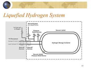
1) The document discusses a proposed Global Technical Regulation (GTR) for hydrogen-fueled vehicles.
2) The GTR would be developed in two phases, first establishing component and subsystem requirements, and then further developing whole vehicle crash tests and future technology assessments.
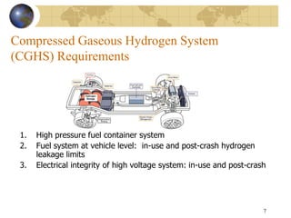
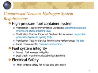
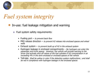
3) Key requirements covered in the draft GTR include compressed hydrogen storage system testing procedures, fuel system integrity for in-use and post-crash situations, and electrical safety standards for high-voltage systems both in-use and post-crash.
![Electrical Safety
Protection from direct and indirect contact from high voltage
In-use:
Protection from direct contact: Protection of (1) IPXXD inside the
passenger or luggage compartment and (2) IPXXB in other areas
Electric isolation – 100 Ω/volt for DC and 500 Ω/volt for AC
• [for combined AC and DC buses: 100 Ω/volt providing (1) the electric
system consists of double or more layers of solid insulators, (2)
mechanically robust protections that have sufficient durability over
vehicle service life such as motor housings, electronic converter cases
or connectors]
Electrical isolation monitoring – Currently applies only to fuel-cell
vehicles
Vehicle functional safety: “At least a momentary indication shall be
given to the driver when the vehicle is in "active driving possible mode''
17](https://image.slidesharecdn.com/grsp-49-28e-230217055619-120ccc51/85/GRSP-49-28e-ppt-17-320.jpg)
![Electrical Safety
Post-crash:
Maximum voltage - 30 VAC and 60 VDC
Resistance isolation - 100 Ω/volt for DC and 500 Ω/volt for AC
• For combined AC/DC buses: 100 Ω/volt providing AC bus meets the
physical protection
[Physical protection: protection of IPXXB] NHTSA is conducting
safety risk study
[Energy option at 2.0 Joules] inconsistent safety criteria with
resistance isolation option.
Electrolyte spillage: Maximum of 7% spillage in 30 minutes
Battery and RESS retention: “RESS located inside the passenger
compartment shall remain in the location... No part of any RESS that is
located outside the passenger compartment for electric safety assessment
shall enter the passenger compartment during or after the impact test.”
18](https://image.slidesharecdn.com/grsp-49-28e-230217055619-120ccc51/85/GRSP-49-28e-ppt-18-320.jpg)
![Outstanding Issues
Some of the test procedures have not been validated
Liquefied hydrogen fuel system: limited experience; post
crash and fire test requirements; limited available test data
Electric safety:
[Post crash barrier option] – NHTSA research on safety risks
Energy option – inconsistent criteria; optional requirement
Material compatibility (Hydrogen embrittlement): CP
to decide. Complete in Phase 2
20](https://image.slidesharecdn.com/grsp-49-28e-230217055619-120ccc51/85/GRSP-49-28e-ppt-20-320.jpg)