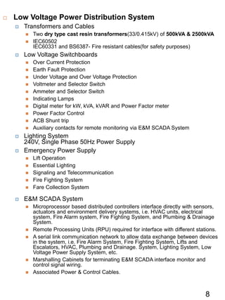
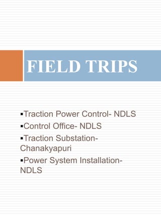
This document provides a summary of the industrial training completed by Lovit Sawhney in July 2015. It includes an overview of key railway electrical terms and a description of cantilever assembly in Delhi Metro stations. It also summarizes tenders reviewed, office structure, and ongoing projects under RVNL including electrification and metro lines. Key sections reviewed are summarized along with field trips to the traction power control office, a traction substation, and power system installations in Delhi.

![Some Projects Under
RVNL
Electrification- Rani-
Palampur(RE/High Rise)
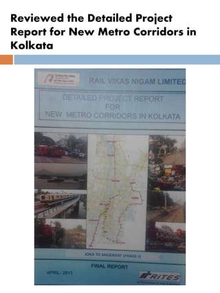
Metro- Kolkata Metro
Joka- BBD bagh(16.72 km)
New Garia- Airport(32 km)
Bara nagar- Barrackpur(12.5
km)[Focus on the above both
right now.]
Others(GEW)
Rishikesh- Karnaprayag= New
Line
Lucknow- Pilibhit= Gauge
conversion
Ahmedabad- Botad= Gauge
Conversion
Palampur- Samakhiali= Doubling](https://image.slidesharecdn.com/bfa315fa-d73b-44e3-a371-c67382ff9d75-160726102810/85/RVNL_Report_ppt-9-320.jpg)


![ppt[1].pptx on industrial training on scada and gis](https://cdn.slidesharecdn.com/ss_thumbnails/ppt1-241018222244-22d92e81-thumbnail.jpg?width=640&height=640&fit=bounds)


