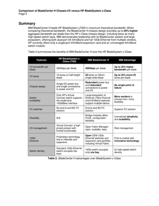
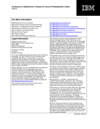
BladeCenter H can provide 25% higher bandwidth per blade and 100% more high-speed
switches than HP BladeSystem c7000 chassis
July 2010
Comparison of BladeCenter H
Chassis I/O versus HP
BladeSystem c7000
By Harsh Kachhy
IBM Systems and Technology Group
Comparison of BladeCenter H Chassis I/O versus HP BladeSystem c-Class
Page 2
Executive Overview
To calculate the I/O capacity of a blade chassis, several design aspects must be taken into
consideration. Aggregate bandwidth is the total of all data flowing into or out of a system. It is
determined by the number of data connections, and the number of lanes available in each
connection, between the blades and the I/O modules. The realizable bandwidth is the
combination of this capability and the technology delivered to exploit it
1
. To determine the
realizable bandwidth, the blade, expansion card, switch module and chassis must be selected
and configured into a specific system, which is then evaluated.
To deliver maximum chassis I/O bandwidth, each component plays a role in the end-to-end
calculation. For example, the blade I/O capacity must consider the number of I/O expansion cards
per blade, the number of ports on each I/O expansion card, the number of lanes available for
each port and the data rate of each lane. The switch module capacity must take into account the
number of ports, the lane count and the lane data rate of internal and external ports. Of course,
the chassis design is central in determining the quantity of blade bays, I/O module bays, and
paths between the blades and I/O modules.
The bandwidth realized from a specific configuration is the combination of the technical
capabilities of the architecture combined with the specific I/O required for the solution. The
various IBM
®
BladeCenter
®
chassis deliver extensive support for today’s networking
technologies, including up to 10Gb Ethernet, up to 8Gb Fibre Channel, and up to 40Gb
InfiniBand
™
.
Each interconnect technology requires a specific data rate and quantity of lanes, as shown in
Table 1. The Aggregate Data Rate is simply the number of lanes provided by the fabric times the
fabric data rate.
Fabric
Data Lanes
Provided
Aggregate
Data Rate
1Gb Ethernet 1 1Gbps
3Gb SAS 1 3Gbps
8Gb Fibre Channel 1 8Gbps
10Gb Ethernet 4 10Gbps
4X QDR InfiniBand 4 40Gbps
Table 1. Lanes required and data rates by fabric
In calculating aggregate bandwidth, the number of lanes between the blades and I/O module
bays are counted. Each lane is a bidirectional electrical “track” across the chassis midplane. From
the start, the BladeCenter H chassis was designed to support future I/O technologies—beyond
the 10G Ethernet or 40G InfiniBand available in market today.
1
Several factors must be considered when determining the realizable throughput of a blade solution, including the blades,
expansion cards, and switch module design.
Comparison of BladeCenter H Chassis I/O versus HP BladeSystem c-Class
Page 3
BladeCenter H Chassis
The IBM BladeCenter H midplane provides interconnection between the blades in the front of the
chassis and the I/O modules in the rear. The ten I/O module bay slots are organized into:
• Standard I/O module bays (2)
• High-speed I/O module bays (4)
• Bridge module bays (2)
• Multipurpose bays (2)—accept either a standard I/O module or a bridge module
The two standard switch module bays support 1Gb Ethernet switch modules to connect each
blade’s built-in Gb Ethernet ports. A single lane is provided from each switch to each of the 14
blades. The four high-speed switch module bays support the high-speed switch modules (10Gb
Ethernet, 4X QDR InfiniBand) and provide four lanes from each switch to each of the 14 blades.
The two multipurpose bays support the connection of the BladeCenter I/O expansion card to their
corresponding switch modules (1Gb Ethernet, 3Gb SAS, 8Gb Fibre Channel). The bridge module
bays and the multipurpose bays—when utilized for a bridge module—provide connectivity to the
high-speed switch modules.
Blade Connections
Each BladeCenter blade (HX5, HS22V, HS22, HS21, and so on) has access to 20 lanes of the
BladeCenter H midplane, as follows:
• 1 single-lane connection to each of the 4 standard switch module bays (4 lanes), and
• 1 4-lane connection to each of the 4 high-speed switch module bays (16 lanes)
Figure 1 represents the connections between a single blade and the I/O modules in the rear of
the chassis. On the left is a single blade with four 1-lane and four 4-lane connections to the eight
I/O module bays. The right side of the diagram represents four vertically-oriented switch module
bays, each receiving a single data lane from each blade, and four horizontally-oriented high-
speed switch bays, each receiving a 4-lane connection from each blade.
Figure 1. BladeCenter H Connection layout
4X
1X
1X
4X
4X
4X
1X
1X
IBM
BladeCenter
blade
Comparison of BladeCenter H Chassis I/O versus HP BladeSystem c-Class
Page 4
BladeCenter H Maximum Theoretical Bandwidth
As discussed, when calculating the maximum theoretical bandwidth of the chassis, each path is
evaluated supporting its highest possible data rate, which is 10Gbps half-duplex (20Gbps full-
duplex) in the case of BladeCenter H. The aggregate bandwidth is the sum of the 14 blades, each
driving 20 data lanes at 10Gbps, or 280 total data lanes:
• 200Gbps half-duplex per blade (20 data lanes at 10Gbps each, inbound or outbound)
• 400Gbps full-duplex per blade (inbound and outbound data rates added together)
• 5.6Tbps full-duplex per chassis (14 blades x 400Gbps)
HP BladeSystem c7000 Maximum Theoretical Bandwidth
The HP BladeSystem c7000 chassis has a different number of blade bays, switch module bays
and available lanes per connection. However, the method of calculating the maximum theoretical
bandwidth is the same. Figure 2 shows the half-height c-Class blade and its connections to the
I/O module bays.
Figure 2. BladeSystem c7000 connection layout
In the c7000, the high-speed switches occupy two horizontally adjacent bays. Figure 2 shows the
maximum I/O connectivity supported for maximum bandwidth: two 1-lane switches, two 2-lane
switches and two 4-lane switches. In other words, the chassis supports 16 total lanes, or 20%
fewer than BladeCenter H:
• Four switches with up to two data lanes per blade (8 lanes)
• Two switches with up to four data lanes per blade (8 lanes)
This configuration appears to provide the highest theoretical bandwidth possible. To calculate the
maximum theoretical bandwidth using the same assumptions described above, the HP c-Class
chassis would have 16 blades with 16 data lanes each, or 256 total data lanes:
• 160Gbps half-duplex per blade (16 data lanes at 10Gbps each, inbound or outbound)
• 320Gbps full-duplex per blade (inbound and outbound data rates added together)
• 5.12Tbps full-duplex per chassis (16 blades x 320Gbps)
2X
2X
2X
2X
4X
4X
HP c-Class
half-height
blade
Switch Switch
Switch Switch
Switch
Switch
Comparison of BladeCenter H Chassis I/O versus HP BladeSystem c-Class
Page 5
Summary
IBM BladeCenter H leads HP BladeSystem c7000 in maximum theoretical bandwidth. When
comparing theoretical bandwidth, the BladeCenter H chassis design provides up to 25% higher
aggregate bandwidth per blade than the HP c-Class chassis design, including twice as many
high-speed switch bays. IBM demonstrates leadership with its BladeCenter system and large
ecosystem, offering both dual-port 4X InfiniBand and full 10Gb Ethernet from multiple vendors.
HP currently offers only a single-port InfiniBand expansion card and an unmanaged InfiniBand
switch module.
Table 2 summarizes the benefits of IBM BladeCenter H over the HP BladeSystem c-Class:
Features
HP BladeSystem c-
Class c7000
IBM BladeCenter H IBM Advantage
I/O bandwidth per
blade
320Gbps per blade 400Gbps per blade
Up to 25% higher
bandwidth per blade
I/O lanes
16 lanes on half-height
blade
20 lanes on 30mm
single-wide blade
Up to 25% more I/O
lanes per blade
Chassis design
Single DC power bus
and single connections
to power and I/O
Redundant power bus
and redundant
connections to power
and I/O
No single point of
failure
Switch
availability
Only HP’s Virtual
Connect switch supports
the single-lane
10GbBase interface
Large ecosystem of
Ethernet, Fibre Channel
and InfiniBand switches
support multiple fabrics
More vendors to
choose from; more
flexibility
FC switches
No end-to-end 8G FC
solution
End-to-end 8G FC
solution
Superior FC solution
Flexibility N/A
Bridge modules allow
FCoE configuration
flexibility
Unmatched simplicity
and scalability
I/O management
Virtual Connect: a high
priced product with
limited functionality
Open Fabric Manager:
open, scalable, easy
Risk management
10Gb
Ethernet
Proprietary technology
that is inflexible and
expensive
Open OEM 10Gb
Ethernet switches and
expansion card portfolio,
including Virtual Fabric
First to market with
innovative technology
Switch density
Standard 10Gb Ethernet
switch occupies two
bays
10Gb switch occupies
only one bay
2x high-speed switch
density
Table 2. BladeCenter H advantages over BladeSystem c-Class
Comparison of BladeCenter H Chassis I/O versus HP BladeSystem c-Class
Page 6
For More Information
IBM BladeCenter Server and options http://ibm.com/systems/bladecenter
IBM Systems Director Service and Support Manager http://ibm.com/support/electronic
IBM System x and BladeCenter Power Configurator http://ibm.com/systems/bladecenter/powerconfig
IBM Standalone Solutions Configuration Tool http://ibm.com/servers/eserver/xseries/library/configtools.html
IBM Configuration and Options Guide http://ibm.com/servers/eserver/xseries/cog
IBM ServerProven Program http://ibm.com/servers/eserver/serverproven/compat/us
IBM Technical Support http://ibm.com/server/support
Other IBM Technical Support Resources http://ibm.com/servers/eserver/techsupport.html
Legal Information
© IBM Corporation 2010
IBM Systems and Technology Group
Dept. U2SA
3039 Cornwallis Road
Research Triangle Park, NC 27709
Produced in the USA
July 2010
All rights reserved.
For a copy of applicable product warranties, write to: Warranty
Information, P.O. Box 12195, RTP, NC 27709, Attn: Dept.
JDJA/B203. IBM makes no representation or warranty
regarding third-party products or services including those
designated as ServerProven or ClusterProven. Telephone
support may be subject to additional charges. For onsite labor,
IBM will attempt to diagnose and resolve the problem remotely
before sending a technician.
IBM, the IBM logo, ibm.com, and BladeCenter are trademarks
of IBM Corporation in the United States and/or other
countries. If these and other IBM trademarked terms are
marked on their first occurrence in this information with a
trademark symbol (® or ™), these symbols indicate U.S.
registered or common law trademarks owned by IBM at the
time this information was published. Such trademarks may
also be registered or common law trademarks in other
countries. For a list of additional IBM trademarks, please see
http://ibm.com/legal/copytrade.shtml.
Other company, product and service names may be
trademarks or service marks of others.
IBM reserves the right to change specifications or other
product information without notice. References in this
publication to IBM products or services do not imply that IBM
intends to make them available in all countries in which IBM
operates. IBM PROVIDES THIS PUBLICATION “AS IS”
WITHOUT WARRANTY OF ANY KIND, EITHER EXPRESS
OR IMPLIED, INCLUDING THE IMPLIED WARRANTIES OF
MERCHANTABILITY AND FITNESS FOR A PARTICULAR
PURPOSE. Some jurisdictions do not allow disclaimer of
express or implied warranties in certain transactions;
therefore, this statement may not apply to you.
This publication may contain links to third party sites that are
not under the control of or maintained by IBM. Access to any
such third party site is at the user's own risk and IBM is not
responsible for the accuracy or reliability of any information,
data, opinions, advice or statements made on these sites. IBM
provides these links merely as a convenience and the
inclusion of such links does not imply an endorsement.
Information in this presentation concerning non-IBM products
was obtained from the suppliers of these products, published
announcement material or other publicly available sources.
IBM has not tested these products and cannot confirm the
accuracy of performance, compatibility or any other claims
related to non-IBM products. Questions on the capabilities of
non-IBM products should be addressed to the suppliers of
those products.
MB, GB and TB = 1,000,000, 1,000,000,000 and
1,000,000,000,000 bytes, respectively, when referring to
storage capacity. Accessible capacity is less; up to 3GB is
used in service partition. Actual storage capacity will vary
based upon many factors and may be less than stated.
Performance is in Internal Throughput Rate (ITR) ratio based
on measurements and projections using standard IBM
benchmarks in a controlled environment. The actual
throughput that any user will experience will depend on
considerations such as the amount of multiprogramming in the
user’s job stream, the I/O configuration, the storage
configuration and the workload processed. Therefore, no
assurance can be given that an individual user will achieve
throughput improvements equivalent to the performance ratios
stated here.
Maximum internal hard disk and memory capacities may
require the replacement of any standard hard drives and/or
memory and the population of all hard disk bays and memory
slots with the largest currently supported drives available.
When referring to variable speed CD-ROMs, CD-Rs, CD-RWs
and DVDs, actual playback speed will vary and is often less
than the maximum possible.
BLW03021-USEN-01

Comparison of BladeCenter H Chassis I/O versus HP BladeSystem c7000

  • 1.
    BladeCenter H canprovide 25% higher bandwidth per blade and 100% more high-speed switches than HP BladeSystem c7000 chassis July 2010 Comparison of BladeCenter H Chassis I/O versus HP BladeSystem c7000 By Harsh Kachhy IBM Systems and Technology Group
  • 2.
    Comparison of BladeCenterH Chassis I/O versus HP BladeSystem c-Class Page 2 Executive Overview To calculate the I/O capacity of a blade chassis, several design aspects must be taken into consideration. Aggregate bandwidth is the total of all data flowing into or out of a system. It is determined by the number of data connections, and the number of lanes available in each connection, between the blades and the I/O modules. The realizable bandwidth is the combination of this capability and the technology delivered to exploit it 1 . To determine the realizable bandwidth, the blade, expansion card, switch module and chassis must be selected and configured into a specific system, which is then evaluated. To deliver maximum chassis I/O bandwidth, each component plays a role in the end-to-end calculation. For example, the blade I/O capacity must consider the number of I/O expansion cards per blade, the number of ports on each I/O expansion card, the number of lanes available for each port and the data rate of each lane. The switch module capacity must take into account the number of ports, the lane count and the lane data rate of internal and external ports. Of course, the chassis design is central in determining the quantity of blade bays, I/O module bays, and paths between the blades and I/O modules. The bandwidth realized from a specific configuration is the combination of the technical capabilities of the architecture combined with the specific I/O required for the solution. The various IBM ® BladeCenter ® chassis deliver extensive support for today’s networking technologies, including up to 10Gb Ethernet, up to 8Gb Fibre Channel, and up to 40Gb InfiniBand ™ . Each interconnect technology requires a specific data rate and quantity of lanes, as shown in Table 1. The Aggregate Data Rate is simply the number of lanes provided by the fabric times the fabric data rate. Fabric Data Lanes Provided Aggregate Data Rate 1Gb Ethernet 1 1Gbps 3Gb SAS 1 3Gbps 8Gb Fibre Channel 1 8Gbps 10Gb Ethernet 4 10Gbps 4X QDR InfiniBand 4 40Gbps Table 1. Lanes required and data rates by fabric In calculating aggregate bandwidth, the number of lanes between the blades and I/O module bays are counted. Each lane is a bidirectional electrical “track” across the chassis midplane. From the start, the BladeCenter H chassis was designed to support future I/O technologies—beyond the 10G Ethernet or 40G InfiniBand available in market today. 1 Several factors must be considered when determining the realizable throughput of a blade solution, including the blades, expansion cards, and switch module design.
  • 3.
    Comparison of BladeCenterH Chassis I/O versus HP BladeSystem c-Class Page 3 BladeCenter H Chassis The IBM BladeCenter H midplane provides interconnection between the blades in the front of the chassis and the I/O modules in the rear. The ten I/O module bay slots are organized into: • Standard I/O module bays (2) • High-speed I/O module bays (4) • Bridge module bays (2) • Multipurpose bays (2)—accept either a standard I/O module or a bridge module The two standard switch module bays support 1Gb Ethernet switch modules to connect each blade’s built-in Gb Ethernet ports. A single lane is provided from each switch to each of the 14 blades. The four high-speed switch module bays support the high-speed switch modules (10Gb Ethernet, 4X QDR InfiniBand) and provide four lanes from each switch to each of the 14 blades. The two multipurpose bays support the connection of the BladeCenter I/O expansion card to their corresponding switch modules (1Gb Ethernet, 3Gb SAS, 8Gb Fibre Channel). The bridge module bays and the multipurpose bays—when utilized for a bridge module—provide connectivity to the high-speed switch modules. Blade Connections Each BladeCenter blade (HX5, HS22V, HS22, HS21, and so on) has access to 20 lanes of the BladeCenter H midplane, as follows: • 1 single-lane connection to each of the 4 standard switch module bays (4 lanes), and • 1 4-lane connection to each of the 4 high-speed switch module bays (16 lanes) Figure 1 represents the connections between a single blade and the I/O modules in the rear of the chassis. On the left is a single blade with four 1-lane and four 4-lane connections to the eight I/O module bays. The right side of the diagram represents four vertically-oriented switch module bays, each receiving a single data lane from each blade, and four horizontally-oriented high- speed switch bays, each receiving a 4-lane connection from each blade. Figure 1. BladeCenter H Connection layout 4X 1X 1X 4X 4X 4X 1X 1X IBM BladeCenter blade
  • 4.
    Comparison of BladeCenterH Chassis I/O versus HP BladeSystem c-Class Page 4 BladeCenter H Maximum Theoretical Bandwidth As discussed, when calculating the maximum theoretical bandwidth of the chassis, each path is evaluated supporting its highest possible data rate, which is 10Gbps half-duplex (20Gbps full- duplex) in the case of BladeCenter H. The aggregate bandwidth is the sum of the 14 blades, each driving 20 data lanes at 10Gbps, or 280 total data lanes: • 200Gbps half-duplex per blade (20 data lanes at 10Gbps each, inbound or outbound) • 400Gbps full-duplex per blade (inbound and outbound data rates added together) • 5.6Tbps full-duplex per chassis (14 blades x 400Gbps) HP BladeSystem c7000 Maximum Theoretical Bandwidth The HP BladeSystem c7000 chassis has a different number of blade bays, switch module bays and available lanes per connection. However, the method of calculating the maximum theoretical bandwidth is the same. Figure 2 shows the half-height c-Class blade and its connections to the I/O module bays. Figure 2. BladeSystem c7000 connection layout In the c7000, the high-speed switches occupy two horizontally adjacent bays. Figure 2 shows the maximum I/O connectivity supported for maximum bandwidth: two 1-lane switches, two 2-lane switches and two 4-lane switches. In other words, the chassis supports 16 total lanes, or 20% fewer than BladeCenter H: • Four switches with up to two data lanes per blade (8 lanes) • Two switches with up to four data lanes per blade (8 lanes) This configuration appears to provide the highest theoretical bandwidth possible. To calculate the maximum theoretical bandwidth using the same assumptions described above, the HP c-Class chassis would have 16 blades with 16 data lanes each, or 256 total data lanes: • 160Gbps half-duplex per blade (16 data lanes at 10Gbps each, inbound or outbound) • 320Gbps full-duplex per blade (inbound and outbound data rates added together) • 5.12Tbps full-duplex per chassis (16 blades x 320Gbps) 2X 2X 2X 2X 4X 4X HP c-Class half-height blade Switch Switch Switch Switch Switch Switch
  • 5.
    Comparison of BladeCenterH Chassis I/O versus HP BladeSystem c-Class Page 5 Summary IBM BladeCenter H leads HP BladeSystem c7000 in maximum theoretical bandwidth. When comparing theoretical bandwidth, the BladeCenter H chassis design provides up to 25% higher aggregate bandwidth per blade than the HP c-Class chassis design, including twice as many high-speed switch bays. IBM demonstrates leadership with its BladeCenter system and large ecosystem, offering both dual-port 4X InfiniBand and full 10Gb Ethernet from multiple vendors. HP currently offers only a single-port InfiniBand expansion card and an unmanaged InfiniBand switch module. Table 2 summarizes the benefits of IBM BladeCenter H over the HP BladeSystem c-Class: Features HP BladeSystem c- Class c7000 IBM BladeCenter H IBM Advantage I/O bandwidth per blade 320Gbps per blade 400Gbps per blade Up to 25% higher bandwidth per blade I/O lanes 16 lanes on half-height blade 20 lanes on 30mm single-wide blade Up to 25% more I/O lanes per blade Chassis design Single DC power bus and single connections to power and I/O Redundant power bus and redundant connections to power and I/O No single point of failure Switch availability Only HP’s Virtual Connect switch supports the single-lane 10GbBase interface Large ecosystem of Ethernet, Fibre Channel and InfiniBand switches support multiple fabrics More vendors to choose from; more flexibility FC switches No end-to-end 8G FC solution End-to-end 8G FC solution Superior FC solution Flexibility N/A Bridge modules allow FCoE configuration flexibility Unmatched simplicity and scalability I/O management Virtual Connect: a high priced product with limited functionality Open Fabric Manager: open, scalable, easy Risk management 10Gb Ethernet Proprietary technology that is inflexible and expensive Open OEM 10Gb Ethernet switches and expansion card portfolio, including Virtual Fabric First to market with innovative technology Switch density Standard 10Gb Ethernet switch occupies two bays 10Gb switch occupies only one bay 2x high-speed switch density Table 2. BladeCenter H advantages over BladeSystem c-Class
  • 6.
    Comparison of BladeCenterH Chassis I/O versus HP BladeSystem c-Class Page 6 For More Information IBM BladeCenter Server and options http://ibm.com/systems/bladecenter IBM Systems Director Service and Support Manager http://ibm.com/support/electronic IBM System x and BladeCenter Power Configurator http://ibm.com/systems/bladecenter/powerconfig IBM Standalone Solutions Configuration Tool http://ibm.com/servers/eserver/xseries/library/configtools.html IBM Configuration and Options Guide http://ibm.com/servers/eserver/xseries/cog IBM ServerProven Program http://ibm.com/servers/eserver/serverproven/compat/us IBM Technical Support http://ibm.com/server/support Other IBM Technical Support Resources http://ibm.com/servers/eserver/techsupport.html Legal Information © IBM Corporation 2010 IBM Systems and Technology Group Dept. U2SA 3039 Cornwallis Road Research Triangle Park, NC 27709 Produced in the USA July 2010 All rights reserved. For a copy of applicable product warranties, write to: Warranty Information, P.O. Box 12195, RTP, NC 27709, Attn: Dept. JDJA/B203. IBM makes no representation or warranty regarding third-party products or services including those designated as ServerProven or ClusterProven. Telephone support may be subject to additional charges. For onsite labor, IBM will attempt to diagnose and resolve the problem remotely before sending a technician. IBM, the IBM logo, ibm.com, and BladeCenter are trademarks of IBM Corporation in the United States and/or other countries. If these and other IBM trademarked terms are marked on their first occurrence in this information with a trademark symbol (® or ™), these symbols indicate U.S. registered or common law trademarks owned by IBM at the time this information was published. Such trademarks may also be registered or common law trademarks in other countries. For a list of additional IBM trademarks, please see http://ibm.com/legal/copytrade.shtml. Other company, product and service names may be trademarks or service marks of others. IBM reserves the right to change specifications or other product information without notice. References in this publication to IBM products or services do not imply that IBM intends to make them available in all countries in which IBM operates. IBM PROVIDES THIS PUBLICATION “AS IS” WITHOUT WARRANTY OF ANY KIND, EITHER EXPRESS OR IMPLIED, INCLUDING THE IMPLIED WARRANTIES OF MERCHANTABILITY AND FITNESS FOR A PARTICULAR PURPOSE. Some jurisdictions do not allow disclaimer of express or implied warranties in certain transactions; therefore, this statement may not apply to you. This publication may contain links to third party sites that are not under the control of or maintained by IBM. Access to any such third party site is at the user's own risk and IBM is not responsible for the accuracy or reliability of any information, data, opinions, advice or statements made on these sites. IBM provides these links merely as a convenience and the inclusion of such links does not imply an endorsement. Information in this presentation concerning non-IBM products was obtained from the suppliers of these products, published announcement material or other publicly available sources. IBM has not tested these products and cannot confirm the accuracy of performance, compatibility or any other claims related to non-IBM products. Questions on the capabilities of non-IBM products should be addressed to the suppliers of those products. MB, GB and TB = 1,000,000, 1,000,000,000 and 1,000,000,000,000 bytes, respectively, when referring to storage capacity. Accessible capacity is less; up to 3GB is used in service partition. Actual storage capacity will vary based upon many factors and may be less than stated. Performance is in Internal Throughput Rate (ITR) ratio based on measurements and projections using standard IBM benchmarks in a controlled environment. The actual throughput that any user will experience will depend on considerations such as the amount of multiprogramming in the user’s job stream, the I/O configuration, the storage configuration and the workload processed. Therefore, no assurance can be given that an individual user will achieve throughput improvements equivalent to the performance ratios stated here. Maximum internal hard disk and memory capacities may require the replacement of any standard hard drives and/or memory and the population of all hard disk bays and memory slots with the largest currently supported drives available. When referring to variable speed CD-ROMs, CD-Rs, CD-RWs and DVDs, actual playback speed will vary and is often less than the maximum possible. BLW03021-USEN-01