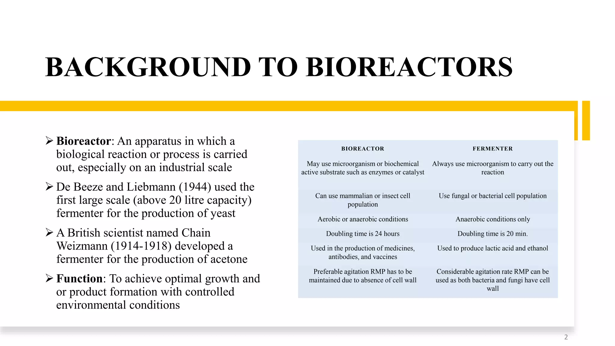
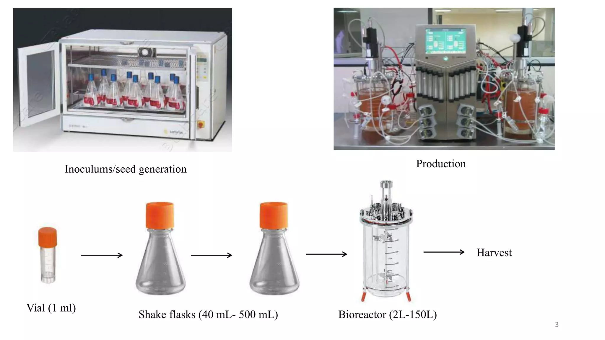
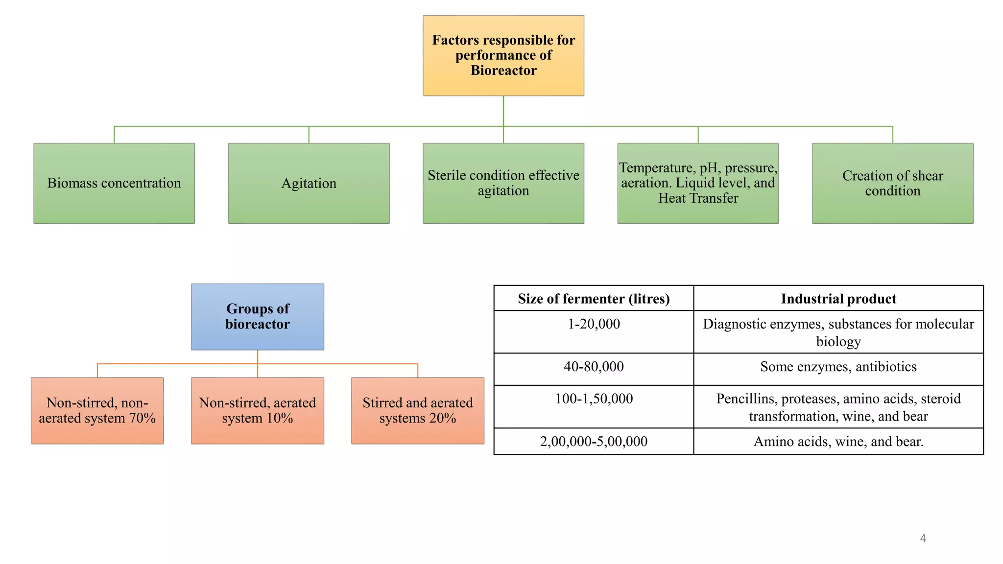
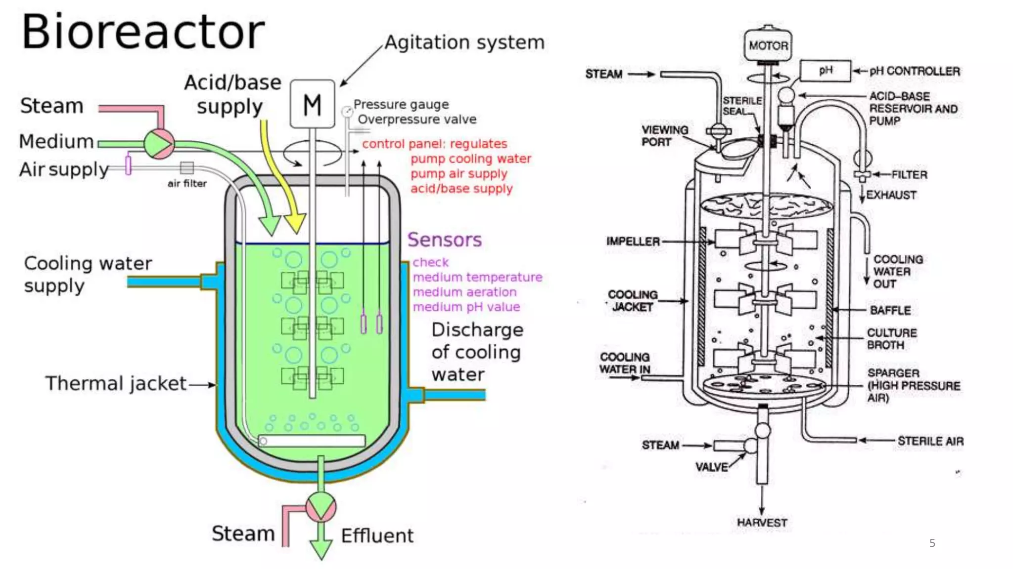
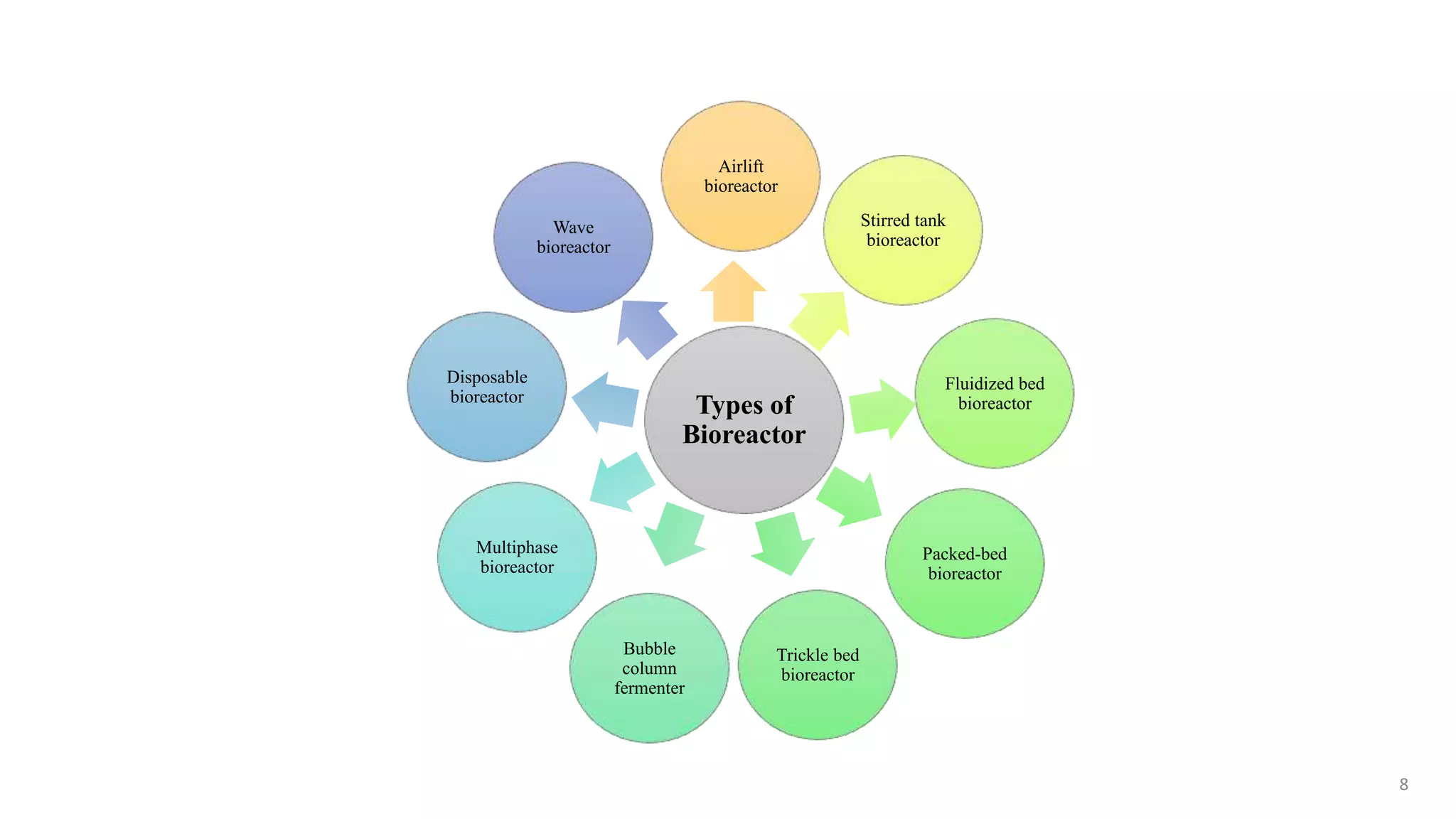
Shubham A. Chinchulkar
M.Tech (Pharm.)
National Institute of Pharmaceutical education and
Research (NIPER), Mohali
+91 7508142388/9730748384
shubhamchinchulkar007@gmail.com
Bioreactor Design and Control
1
BACKGROUND TO BIOREACTORS
 Bioreactor: An apparatus in which a
biological reaction or process is carried
out, especially on an industrial scale
 De Beeze and Liebmann (1944) used the
first large scale (above 20 litre capacity)
fermenter for the production of yeast
 A British scientist named Chain
Weizmann (1914-1918) developed a
fermenter for the production of acetone
 Function: To achieve optimal growth and
or product formation with controlled
environmental conditions
2
BIOREACTOR FERMENTER
May use microorganism or biochemical
active substrate such as enzymes or catalyst
Always use microorganism to carry out the
reaction
Can use mammalian or insect cell
population
Use fungal or bacterial cell population
Aerobic or anaerobic conditions Anaerobic conditions only
Doubling time is 24 hours Doubling time is 20 min.
Used in the production of medicines,
antibodies, and vaccines
Used to produce lactic acid and ethanol
Preferable agitation RMP has to be
maintained due to absence of cell wall
Considerable agitation rate RMP can be
used as both bacteria and fungi have cell
wall
3
Inoculums/seed generation Production
Vial (1 ml)
Shake flasks (40 mL- 500 mL) Bioreactor (2L-150L)
Harvest
Factors responsible for
performance of
Bioreactor
Biomass concentration Agitation
Sterile condition effective
agitation
Temperature, pH, pressure,
aeration. Liquid level, and
Heat Transfer
Creation of shear
condition
Groups of
bioreactor
Non-stirred, non-
aerated system 70%
Non-stirred, aerated
system 10%
Stirred and aerated
systems 20%
Size of fermenter (litres) Industrial product
1-20,000 Diagnostic enzymes, substances for molecular
biology
40-80,000 Some enzymes, antibiotics
100-1,50,000 Pencillins, proteases, amino acids, steroid
transformation, wine, and bear
2,00,000-5,00,000 Amino acids, wine, and bear.
4
5
Sartorius biostat b dcu II
6
DASGIP® Parallel Series Bioreactor Systems from Eppendorf
ambr® 250 high throughput Single-Use Bioreactor Vessels
7
Types of
Bioreactor
Airlift
bioreactor
Stirred tank
bioreactor
Fluidized bed
bioreactor
Packed-bed
bioreactor
Trickle bed
bioreactor
Bubble
column
fermenter
Multiphase
bioreactor
Disposable
bioreactor
Wave
bioreactor
8
Factors
responsible for
bioreactor
designing
Robust vessel
Adequate
aeration and
agitation
Low power
consumption
Temperature
controlled
system
Sampling
facilities
Good vessel
design to reduce
labour in
operation,
harvesting,
clean, and
maintenance
No
evaporation
loss
pH controlled
system
Factors of Bioreactors
9
Bioreactor
A glass vessel with round or flat bottom and a
top flanged carrying a plate
It is sterilize by autoclaving
A glass cylinder with stainless steel top and
bottom plates
It is sterilize in situ
10
Design of bioreactor
Body construction
TEMPERATURE
CONTROL
Aeration and
Agitation
The agitator
(impeller)
Disc turbines
Vanned disc
Open turbine
variable pitch
Marine propeller
Stirrer glands and
bearings
Packed gland seal
Mechanical seal
Magnetic drives
Baffles
Aeration system
(Sparger)
Porous sparger
Orifice sparger
Nozzle sparger
Combined sparger-
agitator
Valves and steam
traps
Gate valves
Globe valves
Piston valves
Needle valves
Pinch valves
Diaphragm valves
Pressure control
valve
Plug valves
Ball valves
Butterfly valves
11
 As large scale fermenters are sterilized in situ and made up from stainless steel
 Less than 4% chromium – steel alloy & more than 4% chromium – stainless steel
 Thin hydrous oxide film on the surface of metal and the film is stabilized by chromium (10-13%) which is considered to
be continuous, non-porous, insoluble, and self healing & it starts healing once come in contact with oxygen or oxidizing
agent
 Molybdenum presence in stainless steel provide resistance to solution of halogen salts
 Chromium 18%, Nickel 10%, and molybdenum 2-2.5% - commonly used fermenter
BODY CONSTRUCTION
12
 The thickness will increase with scale
 For 300000 to 400000 dm3 - 0.7 mm plate for side wall and 10 mm plate for top and bottom which is hemisphere to
withstand pressure
 Reliable aseptic seal –
A. Glass and glass -
B. Glass and metal - seal can be made with compressible gasket a lip seal or ‘O’ ring
C. Metal and metal -
i. Only ‘O’ ring is suitable
ii. Nitryl or butyl rubbers are normally used for these seals as they withstand with fermentation condition
13
TEMPERATURE CONTROL
 Heat will be produce throughout the fermentation process
 If microbial activity and mechanical agitation are responsible for heat generation then this is not ideal for manufacturing
process, further will be achieved by following approaches -
a. Place fermenter in thermostatically controlled bath
b. Use internal heating coil
c. Use heating jacket through which water is circulated
d. Use silicone heating jacket – heating wires between two mats
 For fermenter of 55000 dm3 the cooling area will be 50 to 70 m2 with coolant temperature 14°C, which may be cooled
from 120°C to 30°C in 2.5h from 4h without stirring
 The consumption of cooling water also depends on the culture present inside (bacterial – 500 to 2000 dm3 per hour &
fungal – 2000 to 10,000 dm3 per hour )
14
 To find accurate estimate of heating/cooling requirement we have to consider following parameters -
Qexch = Qmet + Qag + Qgas – Qacc – Qscn – Qevap
 Where,
Qmet = heat generation rate due to microbial metabolism
Qagt = heat generation rate due to mechanical agitation
Qgas = heat generation rate due to aeration power input
Qacc = heat accumulation rate by system
Qexch = heat transfer rate to the surroundings and/or heat exchanger
Qevap = heat loss by evaporation
Qsen = rate of sensible enthalpy gain by flow streams
 When designing large fermenter,
a. The operating temperature and flow condition will determine Qevap and Qsen
b. The choice of agitator, its speed and the aeration rate will determine Qagt
c. The sparger design and aeration rate will determine Qgas
15
 The cooling requirement calculated by following formula –
Qexch = U.Α. ∆𝑇
Where,
A = surface available for heat transfer m2
Q = heat transferred W
U = Overall heat transfer coefficient W/m2K
∆𝑇 = temperature difference between heating and cooling K
 U represent the conductivity of the system and it is influenced by vessel geometry, wall material, flow velocity, fluid
properties, and thickness
 Hence 1/U (reciprocal of overall heat transfer coefficient) is the overall resistance to heat transfer

1
𝑈
=
1
ℎ𝑜
+
1
ℎ𝑖
+
1
ℎ𝑜𝑓
+
1
ℎ𝑖𝑓
+
1
ℎ𝑤
ho = outside film coefficient W/m2K
hi = inside film coefficient W/m2K
hof = outside fouling film coefficient W/m2K
hif = inside fouling film coefficient W/m2K
hw = wall heat transfer coefficient = k/x, W/m2K
k = thermal conductivity of wall W/mK; x = wall thickness m 16
Three methods to determine ∆𝑇 (the temperature driving force) depending on the operating circumstances
If one side of the wall is at a constant temperature, as is often case in stirred fermenter and the coolant temperature rises in
the direction of the coolant flow along a cooling coil:
ΔΤ𝑎𝑚=
𝑇𝑓
−𝑇𝑒 +(𝑇𝑓−𝑇𝑖)
2
If the fluids are in counter or co-current flow and the temperature varies in both fluids then a log mean temperature
difference is appropriate:
ΔΤ𝑚=
𝑇𝑒
−𝑇𝑖
ln(
Δ𝑇𝑒
Δ𝑇𝑖
)
Where,
Te = Temperature of coolant entering the system
Ti = Temperature of coolant leaving the system
Tf = bulk liquid temperature in the vessel
Qexch = U.Α. ∆𝑇
17
Aeration and Agitation
 Provide sufficient oxygen for metabolic requirement, while agitation will helps in uniform oxygen distribution
 Aeration without agitation and aeration with agitation
 If vessel is of height/diameter ratio of 5:1 then it is suitable for non-agitated fermentation
 In such vessel aeration is sufficient to produce high turbulence
Components involved in aeration and agitation –
1. The agitator (impeller)
2. Stirrer glands and bearings
3. Baffles
4. The aeration system (sparger)
18
The agitator (impeller)
Agitator is require to achieve following objectives –
1. Mixing of bulk fluid and gas phase
2. Air dispersion
3. Oxygen transfer
4. Heat transfer
5. Suspension of solid particles
6. Uniform environment
 The proper designing of bioreactor requires to achieve objectives demands for knowledge of most appropriate agitator,
air sparger, baffles, and the best position of feed
 The agitator size, number, speed, and power input need to specify and also crucial factor in bioreactor designing
 The agitator classified as -
19
Disc turbines:
Rectangular vanes
Vanned disc
Open turbine
variable pitch
Marine propeller
20
 Air from sparger hit the undersite of disc and is displaced towards the vane where bubbles are broken up into smaller
bubbles
 The vanes of Open turbine variable pitch and the blades of marine propeller are attached directly to a boss on the
agitator shaft
 In such cases air bubbles do not initially heat any surface before dispersion by vanes or blades
 The propeller being flooded at lower velocity and also less efficient in breaking up a stream of air bubbles the flow it
produces axial rather than radial
 The disc turbine will help to break the bubble occurs at the tip
 It has been show that similar oxygen transfer efficiencies are obtained at the same power input per unit volume,
regardless of agitator type
 To achieve efficient bulk blending in high viscosity fermentation number of agitators have been developed
 The Scaba 6SRGT can handle high flow rate before flooding at a given power input
 This is good in bulk blending but not enough for top to bottom mixing in a large fermenter which leads to lower
concentration of oxygen in broth
21
 Another Prochem Maxflo agitator, which consists four, five or six hydrofoil blades
 Dual impeller combination to achieve good blending and aeration
 Lower impeller acts as gas disperser and upper impeller acts primarily as a device for helping in circulation of vessel
content
 Multi-rod mixing impeller were used in a 15000 dm3 vessel having good efficiency in blending and oxygen transfer
rate but not to come in general use
22
Thank you
23

Bioreactors classifications.pptx

  • 1.
    Shubham A. Chinchulkar M.Tech(Pharm.) National Institute of Pharmaceutical education and Research (NIPER), Mohali +91 7508142388/9730748384 shubhamchinchulkar007@gmail.com Bioreactor Design and Control 1
  • 2.
    BACKGROUND TO BIOREACTORS Bioreactor: An apparatus in which a biological reaction or process is carried out, especially on an industrial scale  De Beeze and Liebmann (1944) used the first large scale (above 20 litre capacity) fermenter for the production of yeast  A British scientist named Chain Weizmann (1914-1918) developed a fermenter for the production of acetone  Function: To achieve optimal growth and or product formation with controlled environmental conditions 2 BIOREACTOR FERMENTER May use microorganism or biochemical active substrate such as enzymes or catalyst Always use microorganism to carry out the reaction Can use mammalian or insect cell population Use fungal or bacterial cell population Aerobic or anaerobic conditions Anaerobic conditions only Doubling time is 24 hours Doubling time is 20 min. Used in the production of medicines, antibodies, and vaccines Used to produce lactic acid and ethanol Preferable agitation RMP has to be maintained due to absence of cell wall Considerable agitation rate RMP can be used as both bacteria and fungi have cell wall
  • 3.
    3 Inoculums/seed generation Production Vial(1 ml) Shake flasks (40 mL- 500 mL) Bioreactor (2L-150L) Harvest
  • 4.
    Factors responsible for performanceof Bioreactor Biomass concentration Agitation Sterile condition effective agitation Temperature, pH, pressure, aeration. Liquid level, and Heat Transfer Creation of shear condition Groups of bioreactor Non-stirred, non- aerated system 70% Non-stirred, aerated system 10% Stirred and aerated systems 20% Size of fermenter (litres) Industrial product 1-20,000 Diagnostic enzymes, substances for molecular biology 40-80,000 Some enzymes, antibiotics 100-1,50,000 Pencillins, proteases, amino acids, steroid transformation, wine, and bear 2,00,000-5,00,000 Amino acids, wine, and bear. 4
  • 5.
  • 6.
  • 7.
    DASGIP® Parallel SeriesBioreactor Systems from Eppendorf ambr® 250 high throughput Single-Use Bioreactor Vessels 7
  • 8.
    Types of Bioreactor Airlift bioreactor Stirred tank bioreactor Fluidizedbed bioreactor Packed-bed bioreactor Trickle bed bioreactor Bubble column fermenter Multiphase bioreactor Disposable bioreactor Wave bioreactor 8
  • 9.
    Factors responsible for bioreactor designing Robust vessel Adequate aerationand agitation Low power consumption Temperature controlled system Sampling facilities Good vessel design to reduce labour in operation, harvesting, clean, and maintenance No evaporation loss pH controlled system Factors of Bioreactors 9
  • 10.
    Bioreactor A glass vesselwith round or flat bottom and a top flanged carrying a plate It is sterilize by autoclaving A glass cylinder with stainless steel top and bottom plates It is sterilize in situ 10
  • 11.
    Design of bioreactor Bodyconstruction TEMPERATURE CONTROL Aeration and Agitation The agitator (impeller) Disc turbines Vanned disc Open turbine variable pitch Marine propeller Stirrer glands and bearings Packed gland seal Mechanical seal Magnetic drives Baffles Aeration system (Sparger) Porous sparger Orifice sparger Nozzle sparger Combined sparger- agitator Valves and steam traps Gate valves Globe valves Piston valves Needle valves Pinch valves Diaphragm valves Pressure control valve Plug valves Ball valves Butterfly valves 11
  • 12.
     As largescale fermenters are sterilized in situ and made up from stainless steel  Less than 4% chromium – steel alloy & more than 4% chromium – stainless steel  Thin hydrous oxide film on the surface of metal and the film is stabilized by chromium (10-13%) which is considered to be continuous, non-porous, insoluble, and self healing & it starts healing once come in contact with oxygen or oxidizing agent  Molybdenum presence in stainless steel provide resistance to solution of halogen salts  Chromium 18%, Nickel 10%, and molybdenum 2-2.5% - commonly used fermenter BODY CONSTRUCTION 12
  • 13.
     The thicknesswill increase with scale  For 300000 to 400000 dm3 - 0.7 mm plate for side wall and 10 mm plate for top and bottom which is hemisphere to withstand pressure  Reliable aseptic seal – A. Glass and glass - B. Glass and metal - seal can be made with compressible gasket a lip seal or ‘O’ ring C. Metal and metal - i. Only ‘O’ ring is suitable ii. Nitryl or butyl rubbers are normally used for these seals as they withstand with fermentation condition 13
  • 14.
    TEMPERATURE CONTROL  Heatwill be produce throughout the fermentation process  If microbial activity and mechanical agitation are responsible for heat generation then this is not ideal for manufacturing process, further will be achieved by following approaches - a. Place fermenter in thermostatically controlled bath b. Use internal heating coil c. Use heating jacket through which water is circulated d. Use silicone heating jacket – heating wires between two mats  For fermenter of 55000 dm3 the cooling area will be 50 to 70 m2 with coolant temperature 14°C, which may be cooled from 120°C to 30°C in 2.5h from 4h without stirring  The consumption of cooling water also depends on the culture present inside (bacterial – 500 to 2000 dm3 per hour & fungal – 2000 to 10,000 dm3 per hour ) 14
  • 15.
     To findaccurate estimate of heating/cooling requirement we have to consider following parameters - Qexch = Qmet + Qag + Qgas – Qacc – Qscn – Qevap  Where, Qmet = heat generation rate due to microbial metabolism Qagt = heat generation rate due to mechanical agitation Qgas = heat generation rate due to aeration power input Qacc = heat accumulation rate by system Qexch = heat transfer rate to the surroundings and/or heat exchanger Qevap = heat loss by evaporation Qsen = rate of sensible enthalpy gain by flow streams  When designing large fermenter, a. The operating temperature and flow condition will determine Qevap and Qsen b. The choice of agitator, its speed and the aeration rate will determine Qagt c. The sparger design and aeration rate will determine Qgas 15
  • 16.
     The coolingrequirement calculated by following formula – Qexch = U.Α. ∆𝑇 Where, A = surface available for heat transfer m2 Q = heat transferred W U = Overall heat transfer coefficient W/m2K ∆𝑇 = temperature difference between heating and cooling K  U represent the conductivity of the system and it is influenced by vessel geometry, wall material, flow velocity, fluid properties, and thickness  Hence 1/U (reciprocal of overall heat transfer coefficient) is the overall resistance to heat transfer  1 𝑈 = 1 ℎ𝑜 + 1 ℎ𝑖 + 1 ℎ𝑜𝑓 + 1 ℎ𝑖𝑓 + 1 ℎ𝑤 ho = outside film coefficient W/m2K hi = inside film coefficient W/m2K hof = outside fouling film coefficient W/m2K hif = inside fouling film coefficient W/m2K hw = wall heat transfer coefficient = k/x, W/m2K k = thermal conductivity of wall W/mK; x = wall thickness m 16
  • 17.
    Three methods todetermine ∆𝑇 (the temperature driving force) depending on the operating circumstances If one side of the wall is at a constant temperature, as is often case in stirred fermenter and the coolant temperature rises in the direction of the coolant flow along a cooling coil: ΔΤ𝑎𝑚= 𝑇𝑓 −𝑇𝑒 +(𝑇𝑓−𝑇𝑖) 2 If the fluids are in counter or co-current flow and the temperature varies in both fluids then a log mean temperature difference is appropriate: ΔΤ𝑚= 𝑇𝑒 −𝑇𝑖 ln( Δ𝑇𝑒 Δ𝑇𝑖 ) Where, Te = Temperature of coolant entering the system Ti = Temperature of coolant leaving the system Tf = bulk liquid temperature in the vessel Qexch = U.Α. ∆𝑇 17
  • 18.
    Aeration and Agitation Provide sufficient oxygen for metabolic requirement, while agitation will helps in uniform oxygen distribution  Aeration without agitation and aeration with agitation  If vessel is of height/diameter ratio of 5:1 then it is suitable for non-agitated fermentation  In such vessel aeration is sufficient to produce high turbulence Components involved in aeration and agitation – 1. The agitator (impeller) 2. Stirrer glands and bearings 3. Baffles 4. The aeration system (sparger) 18
  • 19.
    The agitator (impeller) Agitatoris require to achieve following objectives – 1. Mixing of bulk fluid and gas phase 2. Air dispersion 3. Oxygen transfer 4. Heat transfer 5. Suspension of solid particles 6. Uniform environment  The proper designing of bioreactor requires to achieve objectives demands for knowledge of most appropriate agitator, air sparger, baffles, and the best position of feed  The agitator size, number, speed, and power input need to specify and also crucial factor in bioreactor designing  The agitator classified as - 19
  • 20.
    Disc turbines: Rectangular vanes Vanneddisc Open turbine variable pitch Marine propeller 20
  • 21.
     Air fromsparger hit the undersite of disc and is displaced towards the vane where bubbles are broken up into smaller bubbles  The vanes of Open turbine variable pitch and the blades of marine propeller are attached directly to a boss on the agitator shaft  In such cases air bubbles do not initially heat any surface before dispersion by vanes or blades  The propeller being flooded at lower velocity and also less efficient in breaking up a stream of air bubbles the flow it produces axial rather than radial  The disc turbine will help to break the bubble occurs at the tip  It has been show that similar oxygen transfer efficiencies are obtained at the same power input per unit volume, regardless of agitator type  To achieve efficient bulk blending in high viscosity fermentation number of agitators have been developed  The Scaba 6SRGT can handle high flow rate before flooding at a given power input  This is good in bulk blending but not enough for top to bottom mixing in a large fermenter which leads to lower concentration of oxygen in broth 21
  • 22.
     Another ProchemMaxflo agitator, which consists four, five or six hydrofoil blades  Dual impeller combination to achieve good blending and aeration  Lower impeller acts as gas disperser and upper impeller acts primarily as a device for helping in circulation of vessel content  Multi-rod mixing impeller were used in a 15000 dm3 vessel having good efficiency in blending and oxygen transfer rate but not to come in general use 22
  • 23.