Downloaded 587 times
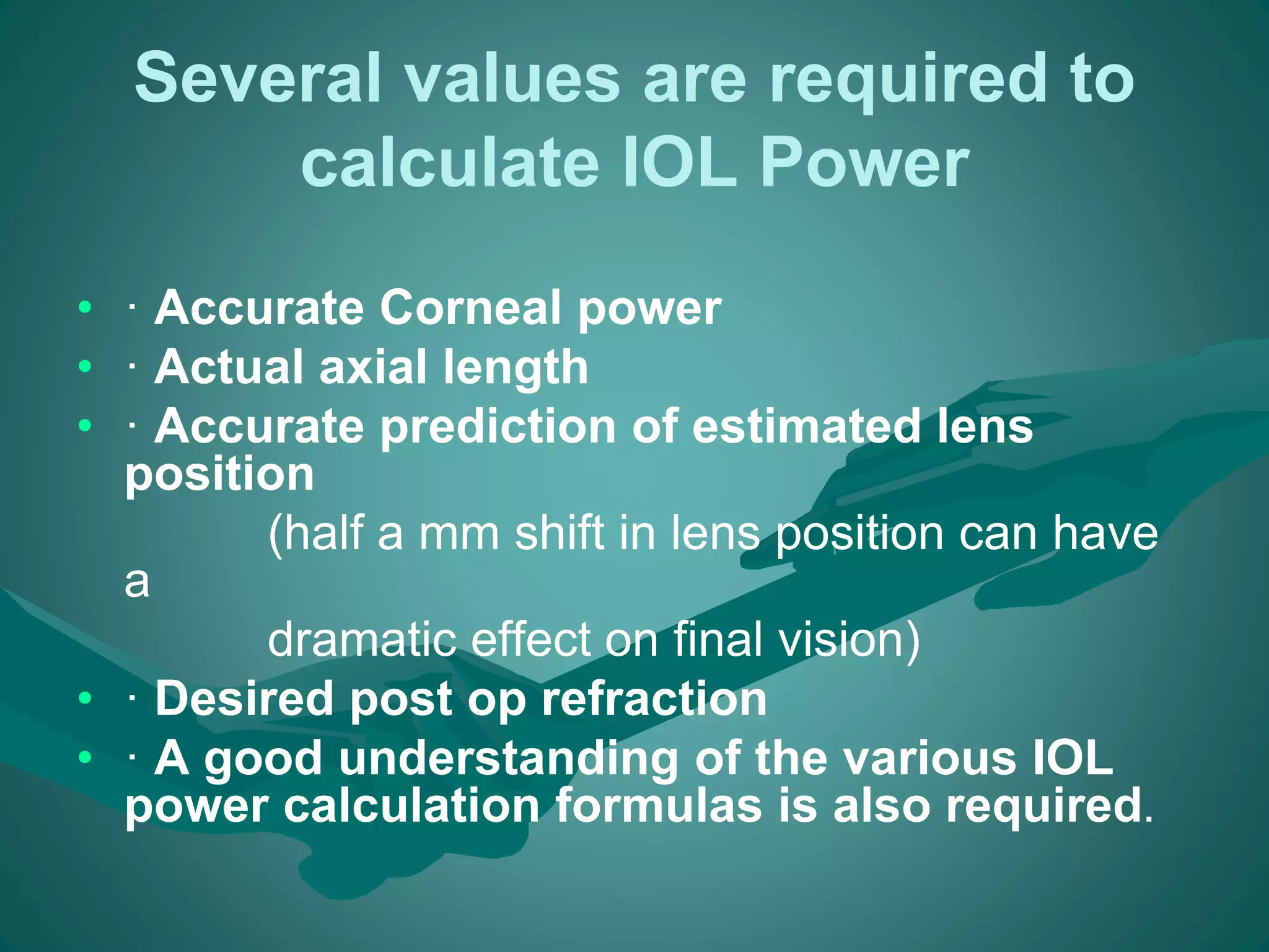
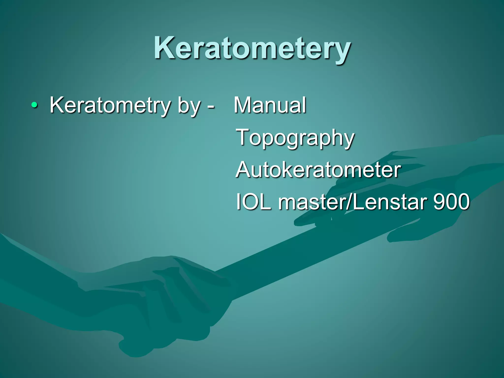
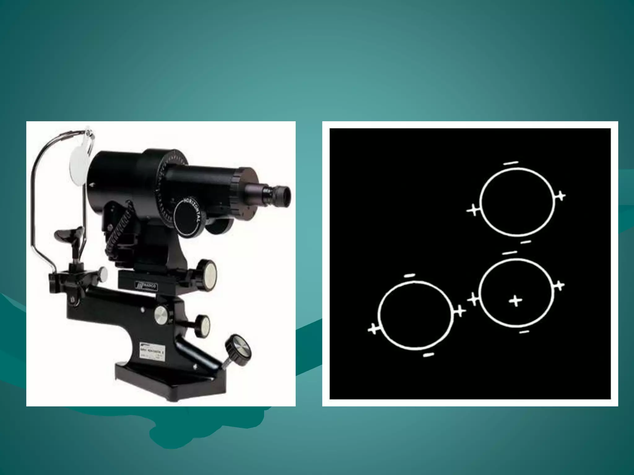
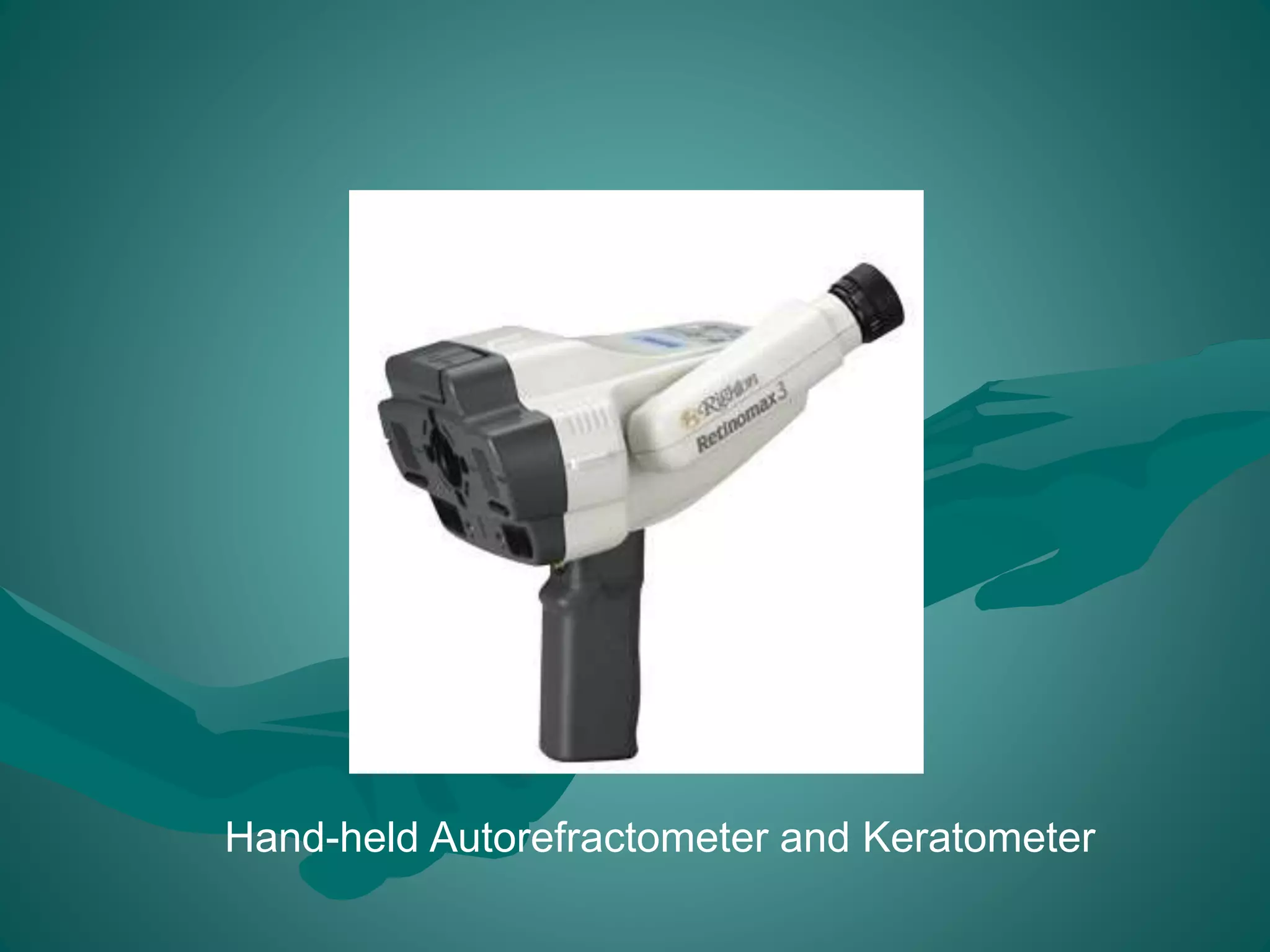


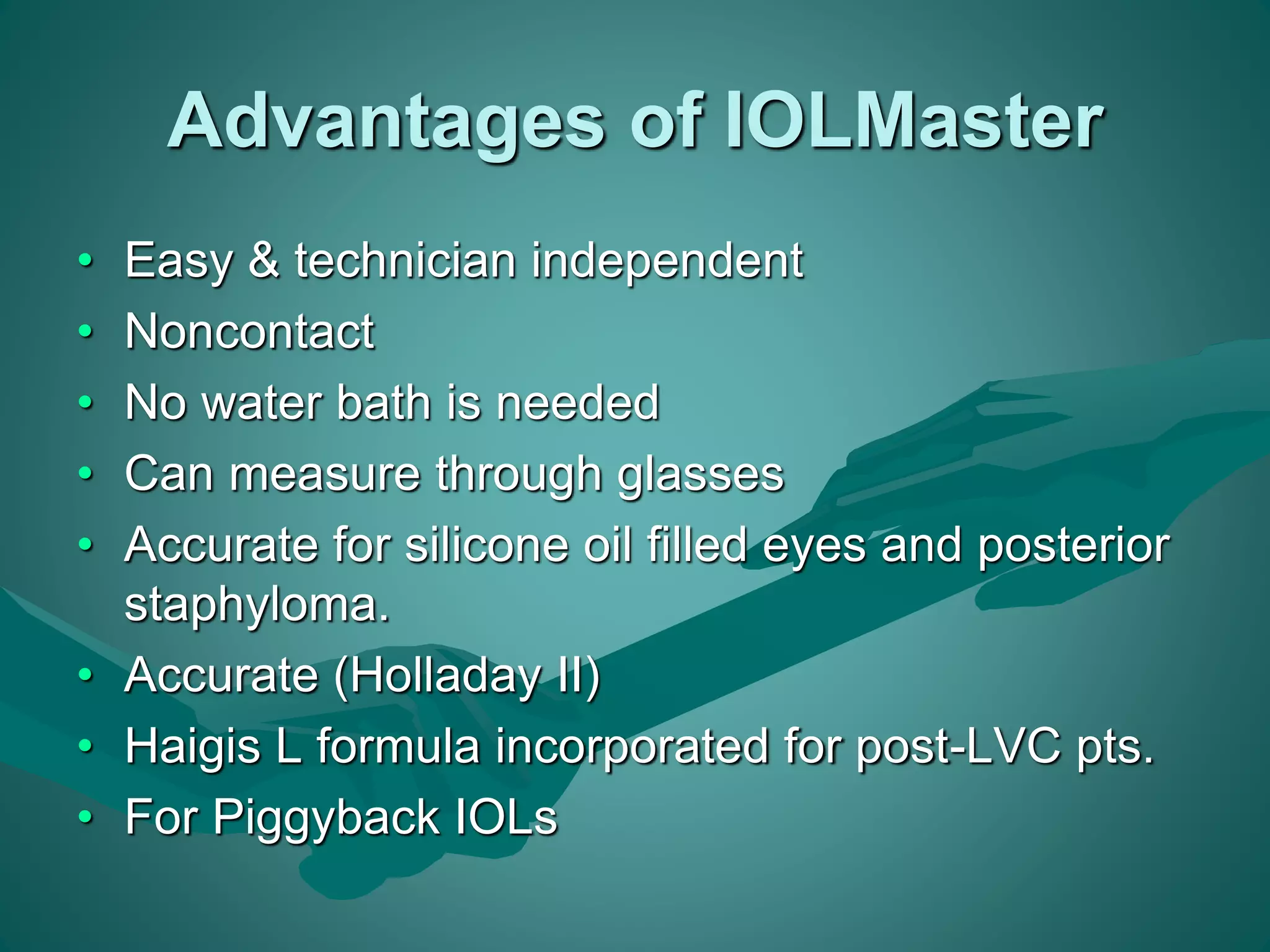
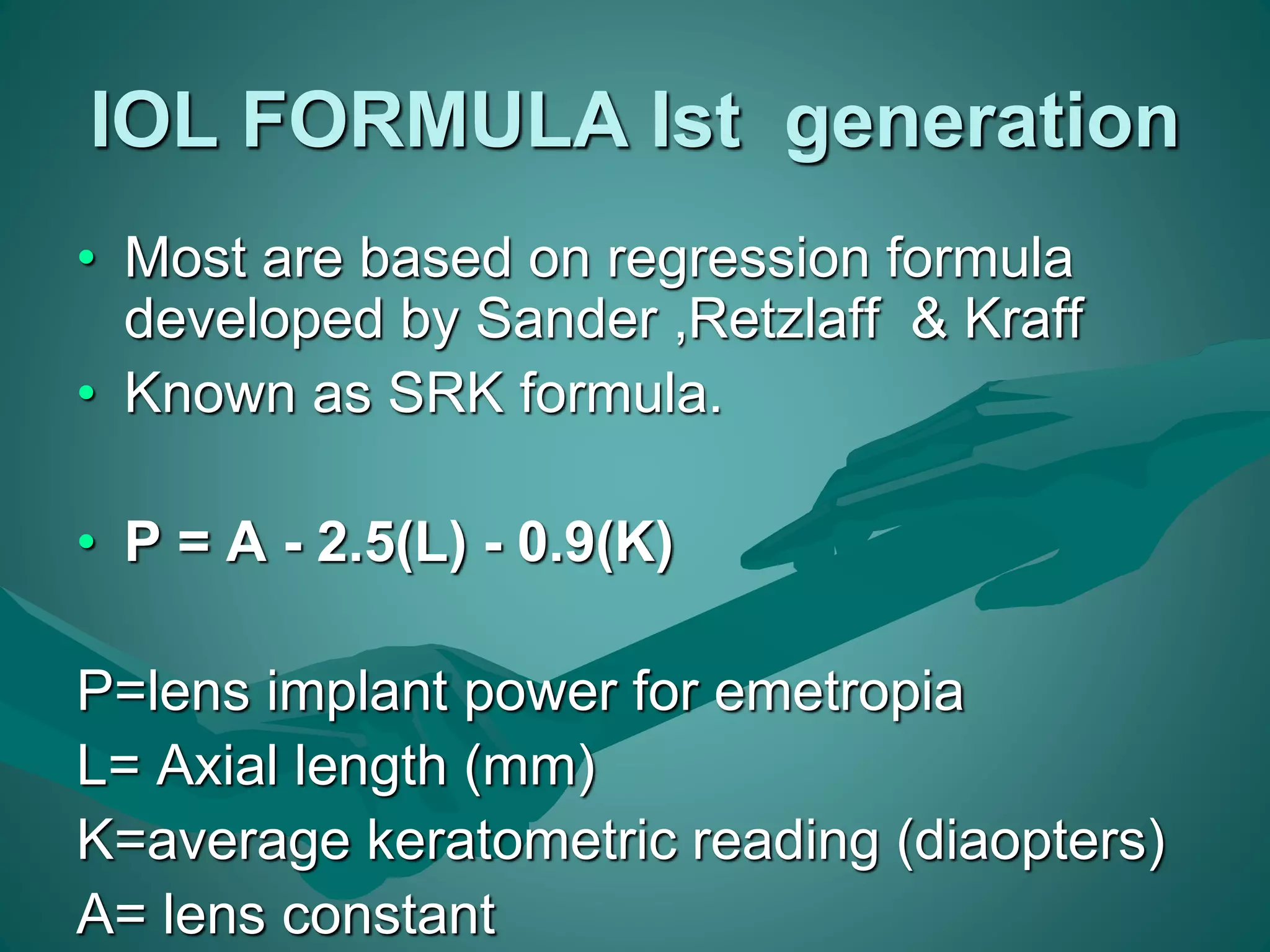
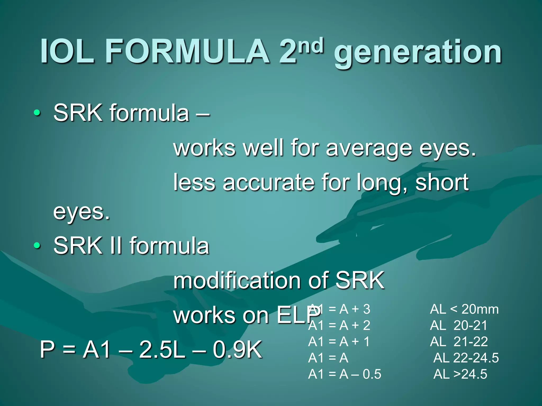
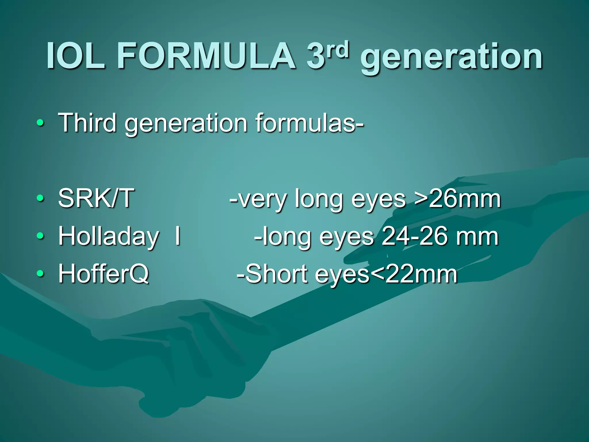
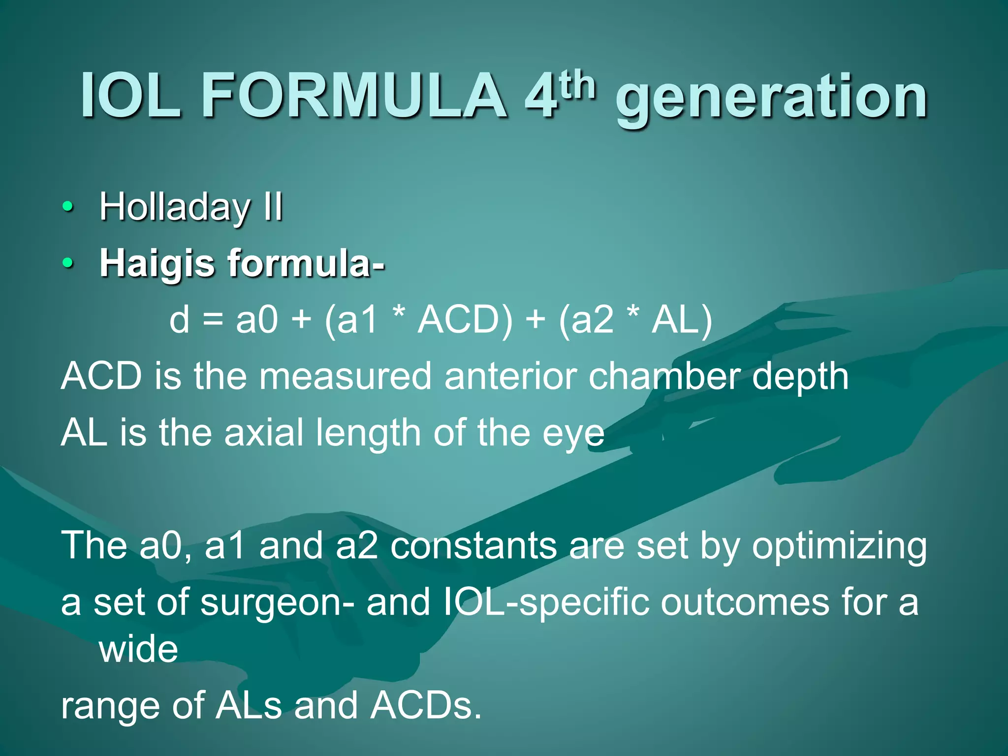
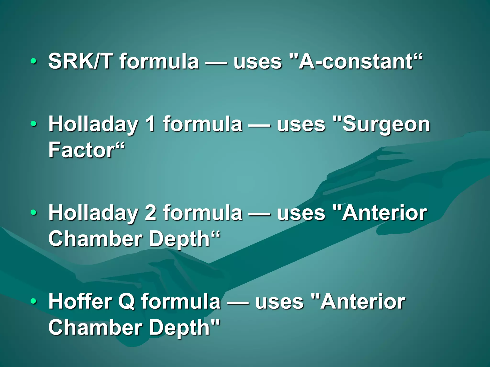
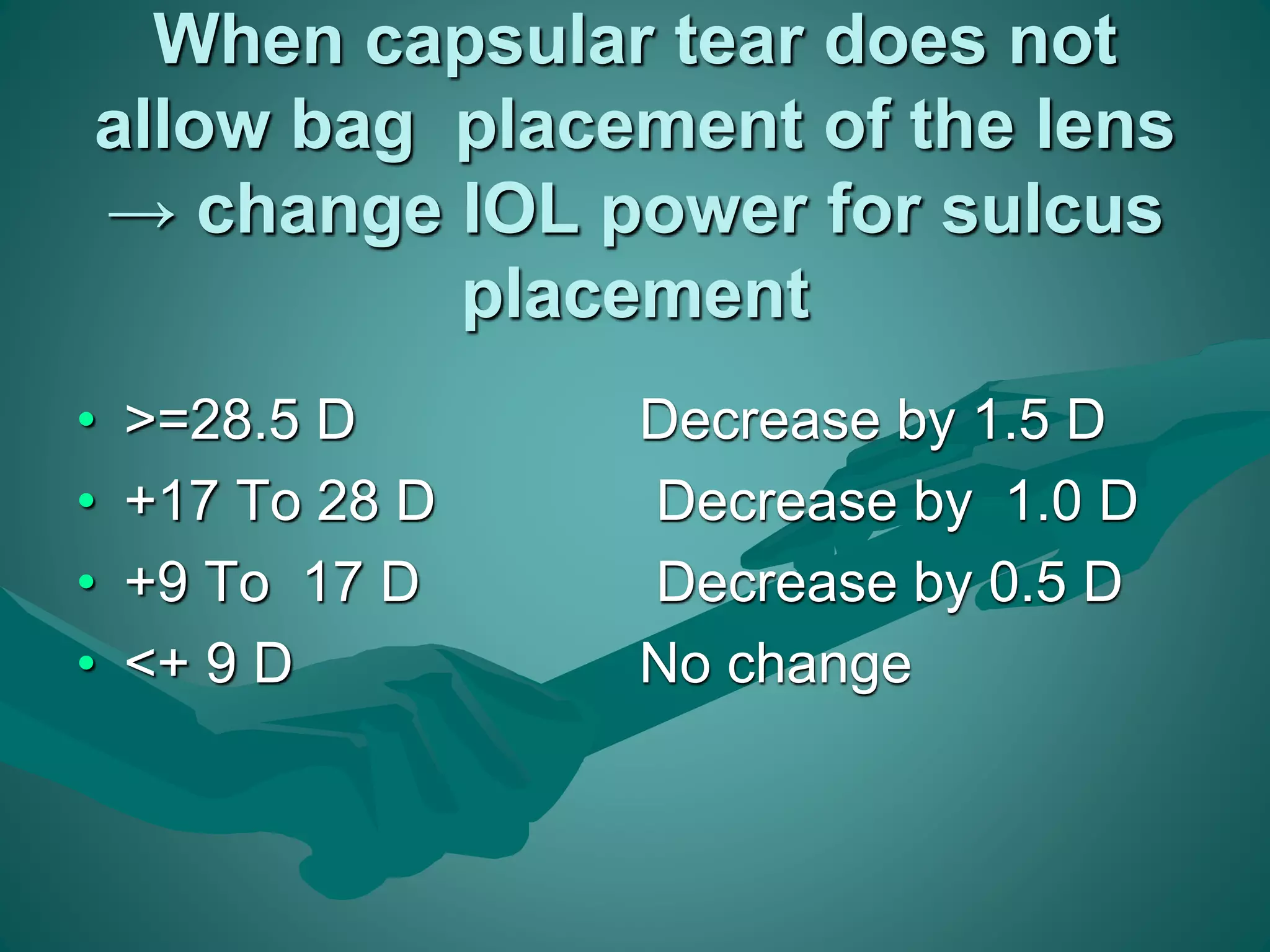
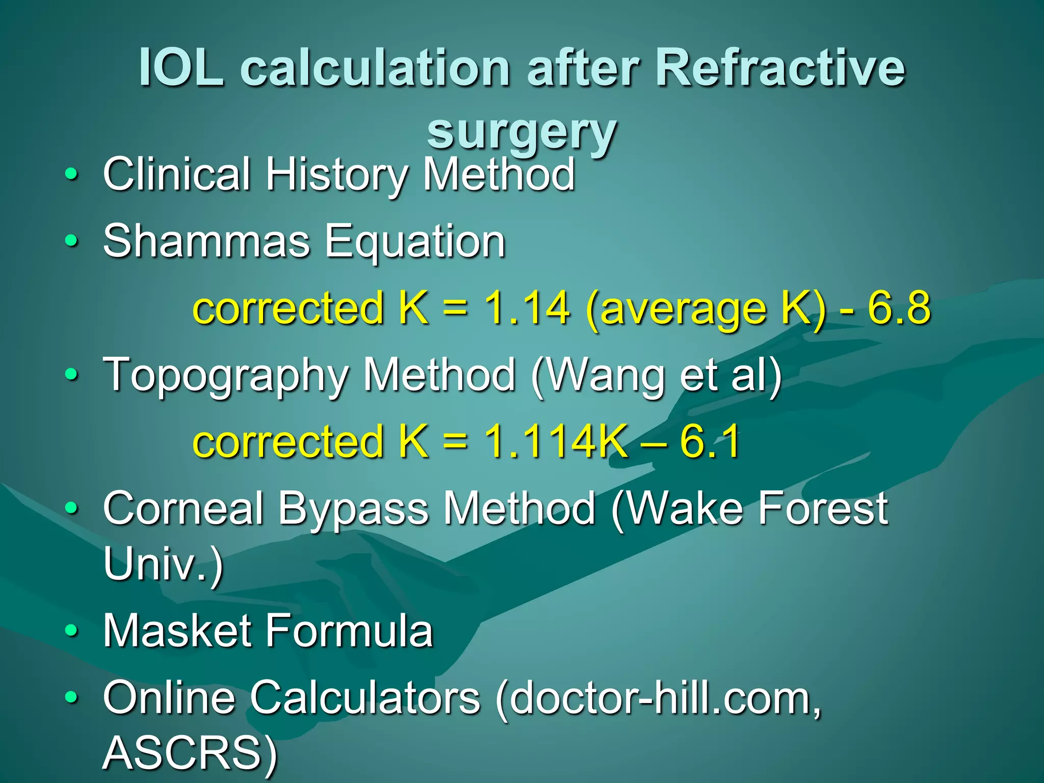
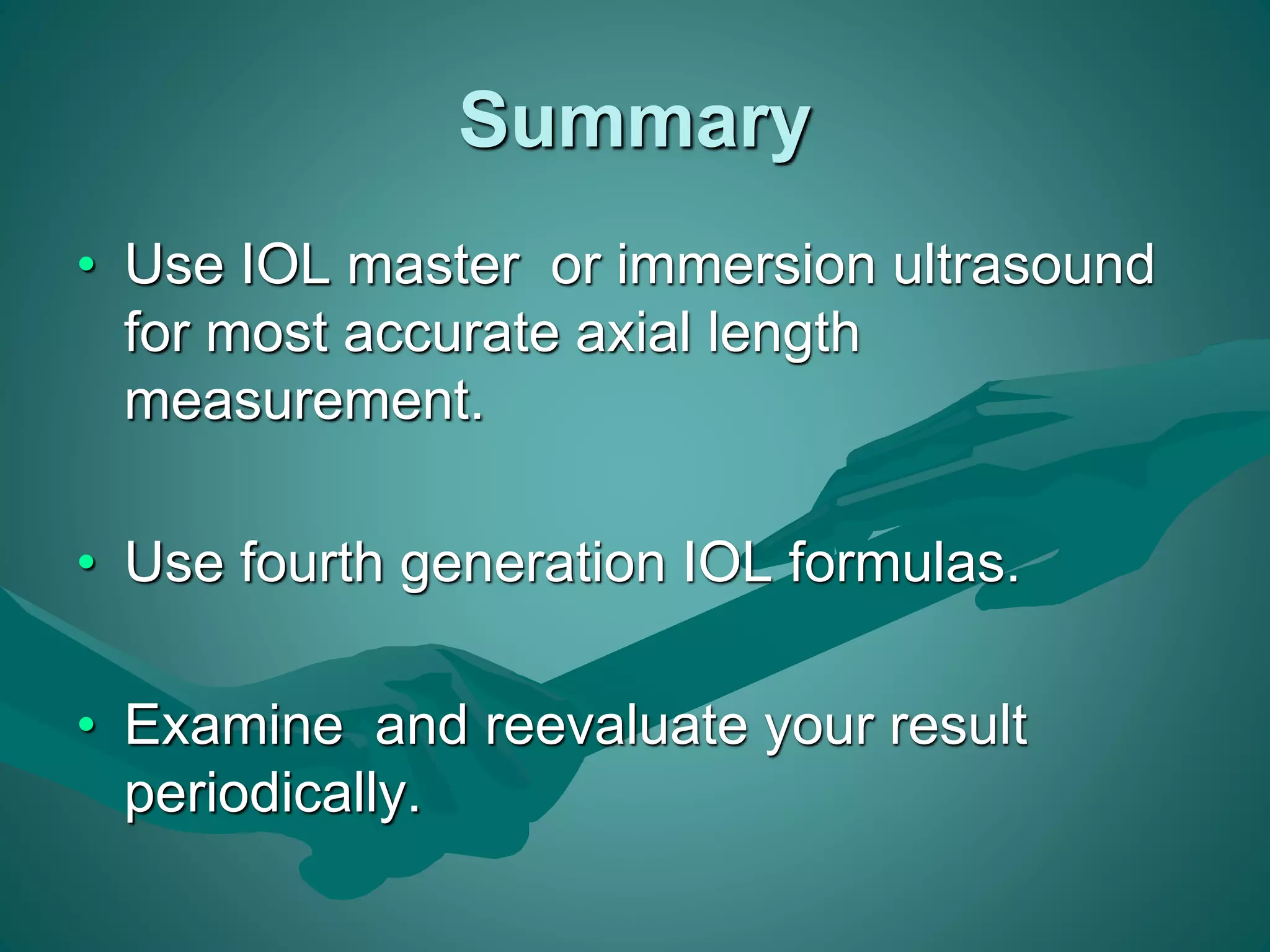

This document discusses various biometry instruments and equipment used to calculate intraocular lens (IOL) power for cataract surgery. It describes how keratometry, A-scan ultrasound biometry, and non-contact devices like the IOLMaster measure important ocular dimensions needed for IOL power calculations, including corneal power, axial length, and anterior chamber depth. It also discusses IOL power calculation formulas from first to fourth generation and factors that influence formula choice, such as eye length, anterior chamber depth, and IOL placement in the eye. Accurate biometry is emphasized as key to achieving the desired postoperative refractive outcome.