
Recommended
More Related Content
What's hot
What's hot (20)
Similar to Lesson 05, bending and shearing stresses
Similar to Lesson 05, bending and shearing stresses (20)
More from Msheer Bargaray
Recently uploaded
Recently uploaded (20)
Lesson 05, bending and shearing stresses
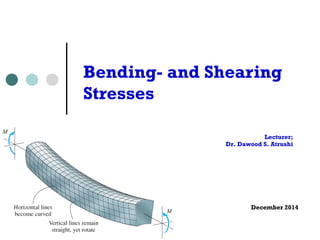
- 1. Lecturer; Dr. Dawood S. Atrushi December 2014 Bending- and Shearing Stresses
- 2. Deflection Curve ¢ Lateral loads acting on a beam cause the beam to bend, thereby deforming the axis of the beam into curve line, this is known as the deflection curve of the beam. December, 2014Bending Stresses - DAT2 Chapter 5 Stresses in Beam (Basic Topics) oduction oads acting transversely to the longitudinal axis ads create shear forces and bending s, stresses and strains due to V are discussed in this chapter l loads acting on a beam cause the bend, thereby deforming the axis of m into curve line, this is known as ction curve of the beam eams are assumed to be symmetric about x-y plane, i.e. y-axis
- 3. Plane of bending The beams are assumed to be symmetric about x-y plane, i.e. y-axis is an axis of symmetric of the cross section, all loads are assumed to act in the x-y plane, then the bending deflection occurs in the same plane, it is known as the plane of bending. Deflection of beam It is the displacement of that point from its original position, measured in y direction. December, 2014Bending Stresses - DAT3
- 4. Pure Bending and Non- uniform Bending Pure bending: M = constant V = dM / dx = 0 December, 2014Bending Stresses - DAT4 1 known as the plane of bending the deflection of the beam is the displacement of that point from its original position, measured in y direction 5.2 Pure Bending and Nonuniform Bending pure bending : M = constant V = dM / dx = 0 pure bending in simple beam and cantilever beam are shown 1 known as the plane of bending the deflection of the beam is the displacement of that point from its original position, measured in y direction 5.2 Pure Bending and Nonuniform Bending pure bending : M = constant V = dM / dx = 0 pure bending in simple beam and cantilever beam are shown
- 5. December, 2014Bending Stresses - DAT5 Non-uniform bending: M ≠ constant V = dM / dx ≠ 0 Simple beam with central region in pure bending and end regions in non- uniform bending. nonuniform bending : M constant V = dM / dx 0 simple beam with central region in pure bending and end regions in nonuniform bending is shown 5.3 Curvature of a Beam
- 6. Curvature of a Beam Consider a cantilever beam subjected to a load P. Choose 2 points m1 and m2 on the deflection curve, l Center of curvature; intersection of their normals at point O’. l radius of curvature ρ; the distance m1O’ l Curvature κ is defined as December, 2014Bending Stresses - DAT6 5.3 Curvature of a Beam consider a cantilever beam subjected to a load P choose 2 points m1 and m2 on the deflection curve, their normals intersect at point O', is called the center of curvature, the distance m1O' is called radius of curvature , and the curvature is defined as = 1 / and we have d = ds simple beam with central region in pure bending and end regions in nonuniform bending is shown 5.3 Curvature of a Beam consider a cantilever beam subjected to a load P choose 2 points m1 and m2 on the deflection curve, their normals intersect at point O', is called the center of curvature, the distance m1O' is called radius of curvature , and the curvature is defined as = 1 /
- 7. We have; ρdθ = ds If the deflection is small ds ≈ dx, then December, 2014Bending Stresses - DAT7 vature of a Beam der a cantilever beam subjected to a P e 2 points m1 and m2 on the n curve, their normals intersect at O', is called the center of curvature, ance m1O' is called radius of e , and the curvature is as = 1 / we have d = ds deflection curve, their normals intersect at point O', is called the center of curvature, the distance m1O' is called radius of curvature , and the curvature is defined as = 1 / and we have d = ds if the deflection is small ds dx, then 1 d d = C = C = C ds dx sign convention for curvature
- 8. We have; ρdθ = ds If the deflection is small ds ≈ dx, then December, 2014Bending Stresses - DAT8 deflection curve, their normals intersect at point O', is called the center of curvature, the distance m1O' is called radius of curvature , and the curvature is defined as = 1 / and we have d = ds if the deflection is small ds dx, then 1 d d = C = C = C ds dx sign convention for curvature 1 / d = ds ion is small ds dx, then 1 d d C = C = C ds dx vention for curvature ent concave upward (convex downward) bent concave downward (convex upward)
- 9. Longitudinal Strains in Beams Consider a portion AB of a beam in pure bending produced by a positive bending moment M, the cross section may be of any shape provided it is symmetric about y-axis; December, 2014Bending Stresses - DAT9 5.4 Longitudinal Strains in Beams consider a portion ab of a beam in pure bending produced by a positive bending moment M, the cross section may be of any shape provided it is symmetric about y-axis under the moment M, its axis is bent into a circular curve, cross 5.4 Longitudinal Strains in Beams consider a portion ab of a beam in pure bending produced by a positive bending moment M, the cross section may be of any shape provided it is symmetric about y-axis under the moment M, its axis is bent into a circular curve, cross
- 10. December, 2014Bending Stresses - DAT10 s section may be of any shape
- 11. re bending produced by a ion may be of any shape nto a circular curve, cross rmal to longitudinal lines Under the moment M, its axis is bent into a circular curve, ¢ cross section mn and pq remain plane and normal to longitudinal lines ¢ the curve is circular ¢ longitudinal lines nq are elongated, and mp are shortened. ¢ the surface ss do not change in length and is called the neutral surface. ¢ its intersection with the cross- sectional plane is called neutral axis, for instance, the z axis is the neutral axis of the cross section. December, 2014Bending Stresses - DAT11
- 12. In the deformed element, denote ρ the distance from 0’ to N.A., thus ρdθ = dx ¢ Consider the longitudinal line ef, the length L1 after bending is December, 2014Bending Stresses - DAT12 consider the longitudinal line ef, the length L1 af y L1 = ( - y) d = dx - C dx y then ef = L1 - dx = - C dx and the strain of line ef is consider the longitudinal line ef, the length L1 af y L1 = ( - y) d = dx - C dx y then ef = L1 - dx = - C dx and the strain of line ef is
- 13. The strain of line ef is: εx vary linear with y. The longitudinal strains in a beam are accompanied by transverse strains in the y and z directions because of the effects of Poisson's ratio! December, 2014Bending Stresses - DAT13 then ef = L1 - dx = - C dx and the strain of line ef is ef y x = CC = - C = - y dx x vary linear with y (the distance from N.S.) y > 0 (above N. S.) = - y < 0 (below N. S.) = + the longitudinal strains in a beam are accompanied by in the y and z directions because of the effects of Po
- 14. 4 in the y and z directions because of the effects of Poisson's ratio Example 5-1 a simply supported beam AB, L = 4.9 m h = 300 mm bent by M0 into a circular arc bottom = x = 0.00125 determine , , and (midpoint deflection) y - 150 = - C = - CCCC x 0.00125 = 120 m 4 in the y and z directions because of the effects of Poisson's ratio Example 5-1 a simply supported beam AB, L = 4.9 m h = 300 mm bent by M0 into a circular arc bottom = x = 0.00125 determine , , and (midpoint deflection) y - 150 = - C = - CCCC x 0.00125 = 120 m Example 1 A simply supported beam AB, L = 4.9 m, h = 300 mm bent by M0 into a circular arc. εbottom = εx = 0.00125 Determine ρ, κ, and δ (midpoint deflection) December, 2014Bending Stresses - DAT14
- 15. 4 m h = 300 mm M0 into a circular arc = x = 0.00125 ne , , and (midpoint on) y - 150 = - C = - CCCC x 0.00125 = 120 m Example 1 Solution December, 2014Bending Stresses - DAT15 4 bent by M0 into a circular arc bottom = x = 0.00125 determine , , and (midpoint deflection) y - 150 = - C = - CCCC x 0.00125 = 120 m 1 = C = 8.33 x 10⁻³ m-1 = (1 - cos ) is large, the deflection curve is very flat
- 16. December, 2014Bending Stresses - DAT16 1 = C = 8.33 x 10⁻³ m-1 = (1 - cos ) is large, the deflection curve is very flat L / 2 8 x 12 then sin = CC = CCCC = 0.020 2 x 2,400 = 0.02 rad = 1.146o then = 120 x 103 (1 - cos 1.146o ) = 24 mm 5.4 Normal Stress in Beams (Linear Elastic Materials) x occurs due to bending, the longitudinal line of the subjected only to tension or compression, if the material is linear elas 1 = C = 8.33 x 10⁻³ m-1 = (1 - cos ) is large, the deflection curve is very flat L / 2 8 x 12 then sin = CC = CCCC = 0.020 2 x 2,400 = 0.02 rad = 1.146o then = 120 x 103 (1 - cos 1.146o ) = 24 mm 5.4 Normal Stress in Beams (Linear Elastic Materials) x occurs due to bending, the longitudinal line subjected only to tension or compression, if the material is lin then = E = - E y 1 = C = 8.33 x 10⁻³ m-1 = (1 - cos ) is large, the deflection curve is very flat L / 2 8 x 12 then sin = CC = CCCC = 0.020 2 x 2,400 = 0.02 rad = 1.146o then = 120 x 103 (1 - cos 1.146o ) = 24 mm 5.4 Normal Stress in Beams (Linear Elastic Materials) x occurs due to bending, the longitudinal line of the subjected only to tension or compression, if the material is linear elas 1 = C = 8.33 x 10⁻³ m-1 = (1 - cos ) is large, the deflection curve is very flat L / 2 8 x 12 then sin = CC = CCCC = 0.020 2 x 2,400 = 0.02 rad = 1.146o then = 120 x 103 (1 - cos 1.146o ) = 24 mm 5.4 Normal Stress in Beams (Linear Elastic Materials) x occurs due to bending, the longitudinal line subjected only to tension or compression, if the material is lin 1 = C = 8.33 x 10⁻³ m-1 = (1 - cos ) is large, the deflection curve is very flat L / 2 8 x 12 then sin = CC = CCCC = 0.020 2 x 2,400 = 0.02 rad = 1.146o then = 120 x 103 (1 - cos 1.146o ) = 24 mm 5.4 Normal Stress in Beams (Linear Elastic Materials) x occurs due to bending, the longitudinal line of the 1 = C = 8.33 x 10⁻³ m-1 = (1 - cos ) is large, the deflection curve is very flat L / 2 8 x 12 then sin = CC = CCCC = 0.020 2 x 2,400 = 0.02 rad = 1.146o then = 120 x 103 (1 - cos 1.146o ) = 24 mm 5.4 Normal Stress in Beams (Linear Elastic Materials) x occurs due to bending, the longitudinal line of the beam subjected only to tension or compression, if the material is linear elastic
- 17. Normal Stress in Beams (Linear Elastic Materials) Consider a beam section subjected to a positive bending moment M. December, 2014Bending Stresses - DAT17 then sin = CC = CCCC = 0.020 2 x 2,400 = 0.02 rad = 1.146o then = 120 x 103 (1 - cos 1.146o ) = 24 mm 5.4 Normal Stress in Beams (Linear Elastic Materials) x occurs due to bending, the longitudinal line of the beam is subjected only to tension or compression, if the material is linear elastic then x = E x = - E y vary linear with distance y from the neutral surface consider a positive bending moment M applied, stresses are positive below N.S. and negative ¢ The longitudinal line of the beam is subjected only to tension or compression, if the material is linear elastic.
- 18. Then; December, 2014Bending Stresses - DAT18 subjected only to tension or compression, if the material is linear ela then x = E x = - E y vary linear with distance y from the neutral surface consider a positive bending moment M applied, stresses are positive below N.S. and negative above N.S. no axial force acts on the cross section, the only resultan thus two equations must satisfy for static equilibrium condition x occurs due to bending, the longitudinal line of the beam is ted only to tension or compression, if the material is linear elastic n x = E x = - E y vary linear with distance y he neutral surface nsider a positive bending nt M applied, stresses are ve below N.S. and negative N.S. no axial force acts on the cross section, the only resultant is M, wo equations must satisfy for static equilibrium condition = 120 x 103 (1 - cos 1.146o ) = 24 mm Stress in Beams (Linear Elastic Materials) occurs due to bending, the longitudinal line of the beam is ly to tension or compression, if the material is linear elastic x = E x = - E y linear with distance y tral surface a positive bending M applied, stresses are low N.S. and negative • σx vary linear with distance y from the neutral surface. • σx Stresses are positive below the N.A., and negative above the N.A.
- 19. ¢ No axial force acts on the cross section, the only resultant is M, thus two equations must satisfy for static equilibrium condition; December, 2014Bending Stresses - DAT19 5 positive below N.S. and negative above N.S. no axial force acts on the cross section, the thus two equations must satisfy for static equilibrium c i.e. Fx = dA = - E y dA = 0 E and are constants at the cross section 5 oment M applied, stresses are ositive below N.S. and negative bove N.S. no axial force acts on the cross section, the only resultan us two equations must satisfy for static equilibrium condition i.e. Fx = dA = - E y dA = 0 E and are constants at the cross section, thus we hav y dA = 0 we conclude that the neutral axis passes th l E and κ are constants at the cross section, thus we have
- 20. We conclude that the neutral axis passes through the centroid of the cross section. The moment resultant of stress σx is; December, 2014Bending Stresses - DAT20 section, also for the symmetrical condition in y axis, the pass through the centroid, hence, the origin of coordinates O the centroid of the cross section the moment resultant of stress x is dM = - x y dA then M = - x y dA = E y2 dA = E M = E I where I = y2 dA is the moment of inertia of the area w. r. t. z axis 1 M we conclude that the neutral axis passes through the cont section, also for the symmetrical condition in y axis, the pass through the centroid, hence, the origin of coordinates the centroid of the cross section the moment resultant of stress x is dM = - x y dA then M = - x y dA = E y2 dA = E M = E I where I = y2 dA is the moment of inertia of the area w. r. t. z axis e that the neutral axis passes through the controid of the cross r the symmetrical condition in y axis, the y axis must e centroid, hence, the origin of coordinates O is located at the cross section resultant of stress x is M = - x y dA = - x y dA = E y2 dA = E y2 dA = E I = y2 dA is the moment of inertia of the cross-sectional axis we conclude that the neutral axis passes through the cont section, also for the symmetrical condition in y axis, the pass through the centroid, hence, the origin of coordinates the centroid of the cross section the moment resultant of stress x is dM = - x y dA then M = - x y dA = E y2 dA = E M = E I where I = y2 dA is the moment of inertia of the area w. r. t. z axis we conclude that the neutral axis passes throug section, also for the symmetrical condition in y pass through the centroid, hence, the origin of coo the centroid of the cross section the moment resultant of stress x is dM = - x y dA then M = - x y dA = E y2 dA M = E I where I = y2 dA is the moment of ine area w. r. t. z axis I is the moment of inertia of the cross-sectional Then;
- 21. December, 2014Bending Stresses - DAT21 where I = y2 dA is the moment of inertia of the cros area w. r. t. z axis 1 M thus = C = CC E I this is the moment-curvature equation, and EI is called flexural rigidity + M => + curvature - M => - curvature the normal stress is M M y x = - E y = - E y (CC) = - CC Thus; This is the Moment- Curvature Equation. EI is called Flexural Rigidity. M = E I where I = y2 dA is the moment of inertia of the cross-sectiona area w. r. t. z axis 1 M thus = C = CC E I this is the moment-curvature equation, and EI is called flexural rigidity + M => + curvature - M => - curvature the normal stress is M M y
- 22. The normal stress is; December, 2014Bending Stresses - DAT22 6 the normal stress is M M y x = - E y = - E y (CC) = - CC E I I this is called the flexure formula, the stress x stresses or flexural stresses 6 ture ure M M y y = - E y (CC) = - CC E I I lexure formula, the stress x is called bending sses Flexture Formula σx is called bending stresses or flextural stresses σx is varying linearly 6 + M => + curvature - M => - curvature the normal stress is M M y x = - E y = - E y (CC) = - CC E I I this is called the flexure formula, the stress x stresses or flexural stresses
- 23. The maximum tensile and compressive stresses occur at the points located farthest from the N.A. December, 2014Bending Stresses - DAT23 ve est M x 1 / I m tensile and compressive t the points located farthest M c1 M - CC = - C I S1 M c2 M CC = C I S2 I I = C , S2 = C are known as the section modul
- 24. December, 2014Bending Stresses - DAT24 the maximum tensile and compressive stresses occur at the points located farthest from the N.A. M c1 M 1 = - CC = - C I S1 M c2 M 2 = CC = C I S2 I I where S1 = C , S2 = C are known as the section mo c1 c2 if the cross section is symmetric w.r.t. z axis (double symmetric section), then c1 = c2 = c M c M thus S1 = S2 and 1 = - 2 = - CC = - C I S The maximal stresses; the maximum tensile and compressive stresses occur at the points located farthest from the N.A. M c1 M 1 = - CC = - C I S1 M c2 M 2 = CC = C I S2 I I where S1 = C , S2 = C are known as the section m c1 c2 if the cross section is symmetric w.r.t. z axis (double symmet section), then c1 = c2 = c M c M thus S1 = S2 and 1 = - 2 = - CC = - C I S S1 and S2 are known as the section moduli 7 thus S1 = S2 and 1 = - 2 = - CC = - C I S for rectangular cross section b h3 b h2 I = CC S = CC 12 6 for circular cross section d 4 d 3 I = CC S = CC 64 32 the preceding analysis of normal stress in beams concerned pure bending, no shear force in the case of nonuniform bending (V 0), shear force produces warping x vary linearly with y x M x 1 / I the maximum tensile and compressive esses occur at the points located farthest m the N.A. M c1 M 1 = - CC = - C I S1 M c2 M 2 = CC = C I S2 I I where S1 = C , S2 = C are known as the section moduli c1 c2 if the cross section is symmetric w.r.t. z axis (double symmetric cross ction), then c1 = c2 = c
- 25. Example 2 A steel wire of diameter d = 4 mm is bent around a cylindrical drum of radius R0 = 0.5 m, E = 200 Gpa. Determine M and σmax. December, 2014Bending Stresses - DAT25 when we have nonuniform bending e flexure formula gives results in the beam where the stress distribution t disrupted by irregularities in the shape, or by discontinuous in loading rwise, stress concentration occurs) mple 5-2 steel wire of diameter d = 4 mm nt around a cylindrical drum of radius = 0.5 m = 200 GPa pl = 1200 MPa etermine M and max he radius of curvature of the wire is d
- 26. The radius of curvature of the wire is; December, 2014Bending Stresses - DAT26 is bent around a cylindrical drum of radius R0 = 0.5 m E = 200 GPa pl = 1200 MPa determine M and max the radius of curvature of the wire is d = R0 + C 2 EI 2 EI E d 4 M = C = CCCC = CCCCC 2 R0 + d 32(2R0 + d) (200 x 103 ) 44 = CCCCCCC = 5007 N-mm = 5.007 N 32 (2 x 500 + 4) M M M d 2 EI d max = C = CCC = CC = CCCCCC = C S I / (d/2) 2 I 2 I (2 R0 + d) 2 R a steel wire of diameter d = 4 mm is bent around a cylindrical drum of radius R0 = 0.5 m E = 200 GPa pl = 1200 MPa determine M and max the radius of curvature of the wire is d = R0 + C 2 EI 2 EI E d 4 M = C = CCCC = CCCCC 2 R0 + d 32(2R0 + d) (200 x 103 ) 44 = CCCCCCC = 5007 N-mm = 5.007 N 32 (2 x 500 + 4) M M M d 2 EI d a steel wire of diameter d = 4 mm is bent around a cylindrical drum of radius R0 = 0.5 m E = 200 GPa pl = 1200 MPa determine M and max the radius of curvature of the wire is d = R0 + C 2 EI 2 EI E d 4 M = C = CCCC = CCCCC 2 R0 + d 32(2R0 + d) (200 x 103 ) 44 = CCCCCCC = 5007 N-mm = 5.007 N-m 32 (2 x 500 + 4) M M M d 2 EI d E d max = C = CCC = CC = CCCCCC = CCCC Example 2 Solution Bending moment;
- 27. The maximum bending stress; December, 2014Bending Stresses - DAT27 8 EI 2 EI E d 4 M = C = CCCC = CCCCC 2 R0 + d 32(2R0 + d) (200 x 103 ) 44 = CCCCCCC = 5007 N-mm = 5.0 32 (2 x 500 + 4) M M M d 2 EI d max = C = CCC = CC = CCCCCC = S I / (d/2) 2 I 2 I (2 R0 + d) 200 x 103 x 4 = CCCCCC = 796.8 MPa < 1,200 M 2 x 500 + 4 8 d R0 + C 2 EI 2 EI E d 4 = C = CCCC = CCCCC 2 R0 + d 32(2R0 + d) (200 x 103 ) 44 = CCCCCCC = 5007 N-mm = 5.007 N-m 32 (2 x 500 + 4) M M d 2 EI d E d = CCC = CC = CCCCCC = CCCC I / (d/2) 2 I 2 I (2 R0 + d) 2 R0 + d
- 28. = 796.8 MPa < 1,200 MPa (OK) = 6.7 m 50 kN 700 mm nsile and A simple beam AB of length L = 6.7 m q = 22kN/m, P = 50kN b = 220mm, h = 700mm Determine the maximum tensile and compressive stresses due to bending. December, 2014Bending Stresses - DAT28 Example 3
- 29. 1) Construct the M-diagram and V- diagram. 2) Find the max. bending moment along the beam. 3) Calculate the max. bending stresses. December, 2014Bending Stresses - DAT29 Example 3 Solution
- 30. 4 CC = 796.8 MPa < 1,200 MPa (OK) 4 h L = 6.7 m = 50 kN = 700 mm tensile and nding a and M-dia of Mmax m of the section is 22 x 0.72 CCC = 0.018 m3 M- and V-diagram. December, 2014Bending Stresses - DAT30 Max. bending stress occurs at the section of Mmax. Mmax= 193.9 kN-m
- 31. The section modulus S is; December, 2014Bending Stresses - DAT31 Mmax = 193.9 kN-m the section modulus S of the section is b h2 0.22 x 0.72 S = CC = CCCC = 0.018 m3 6 6 M 139.9 kN-m t = 2 = C = CCCCC = 10.8 MPa S 0.018 m3 M c = 1 = - C = - 10.8 MPa S Example 5-4 an overhanged beam ABC subjected firstly, construct the V-dia and M-dia max occurs at the section of Mmax Mmax = 193.9 kN-m the section modulus S of the section is b h2 0.22 x 0.72 S = CC = CCCC = 0.018 m3 6 6 M 139.9 kN-m t = 2 = C = CCCCC = 10.8 MPa S 0.018 m3 M c = 1 = - C = - 10.8 MPa S firstly, construct the V-dia and M-dia max occurs at the section of Mmax Mmax = 193.9 kN-m the section modulus S of the section is b h2 0.22 x 0.72 S = CC = CCCC = 0.018 m3 6 6 M 139.9 kN-m t = 2 = C = CCCCC = 10.8 MPa S 0.018 m3 M c = 1 = - C = - 10.8 MPa S Example 5-4 The max. bending stresses are;
- 32. An overhanged beam ABC subjected uniform load of intensity q = 3.2 kN/m for the cross section (channel section) t = 12 mm, b = 300 mm, h = 80 mm. Determine the maximum tensile and compressive stresses in the beam. December, 2014Bending Stresses - DAT32 Example 4= 0.018 m3 9 kN-m CCC = 10.8 MPa 18 m3 .8 MPa ected m = 12 mm b = 300 mm h = 80 mm etermine the maximum tensile and ressive stresses in the beam onstruct the V-dia. and M-dia. first e can find + Mmax = 2.205 kN-m - Mmax = - 3.6 kN-m ext, we want to find the N. A. of the section A(mm2 ) y(mm) A y (mm3 ) 1 3,312 6 19,872 2 960 40 38,400 3 960 40 38,400
- 33. = 80 mm and a. first 5 kN-m kN-m he section 3 December, 2014Bending Stresses - DAT33 9 CCCCC = 10.8 MPa 0.018 m3 - 10.8 MPa ubjected kN/m ction) t = 12 mm b = 300 mm h = 80 mm determine the maximum tensile and compressive stresses in the beam construct the V-dia. and M-dia. first we can find + Mmax = 2.205 kN-m - Mmax = - 3.6 kN-m next, we want to find the N. A. of the section A(mm2 ) y(mm) A y (mm3 ) A1 3,312 6 19,872 A2 960 40 38,400 A3 960 40 38,400 total 5,232 96,672 Ai yi 96,672 c1 = CCC = CCC = 18.48 mm Ai 5,232 - Mmax = - 3.6 kN-m , we want to find the N. A. of the section A(mm2 ) y(mm) A y (mm3 ) 3,312 6 19,872 960 40 38,400 960 40 38,400 l 5,232 96,672 Ai yi 96,672 c1 = CCC = CCC = 18.48 mm Ai 5,232 c2 = h - c1 = 61.52 mm ment of inertia of the section is Find the N.A. of the section:
- 34. December, 2014Bending Stresses - DAT34 t = 12 mm b = 300 mm h = 80 mm determine the maximum tensile and compressive stresses in the beam construct the V-dia. and M-dia. first we can find + Mmax = 2.205 kN-m - Mmax = - 3.6 kN-m next, we want to find the N. A. of the section A(mm2 ) y(mm) A y (mm3 ) A1 3,312 6 19,872 A2 960 40 38,400 A3 960 40 38,400 total 5,232 96,672 Ai yi 96,672 c1 = CCC = CCC = 18.48 mm Ai 5,232 we can find + Mmax = 2.205 kN-m - Mmax = - 3.6 kN-m next, we want to find the N. A. of the sectio A(mm2 ) y(mm) A y (mm3 ) A1 3,312 6 19,872 A2 960 40 38,400 A3 960 40 38,400 total 5,232 96,672 Ai yi 96,672 c1 = CCC = CCC = 18.48 mm Ai 5,232 c2 = h - c1 = 61.52 mm moment of inertia of the section is Iz1 = Izc + A1 d1 2 72 8 mm mm
- 35. Moment of inertia of the section is December, 2014Bending Stresses - DAT35 10 c2 = h - c1 = 61.52 mm moment of inertia of the section is Iz1 = Izc + A1 d1 2 1 1 Izc = C (b - 2t) t3 = C 276 x 123 = 39744 mm4 12 12 d1 = c1 - t / 2 = 12.48 mm Iz1 = 39,744 + 3,312 x 12.482 = 555,600 mm4 similarly Iz2 = Iz3 = 956,000 mm4 10 c2 = h - c1 = 61.52 mm moment of inertia of the section is Iz1 = Izc + A1 d1 2 1 1 Izc = C (b - 2t) t3 = C 276 x 123 = 39744 mm4 12 12 d1 = c1 - t / 2 = 12.48 mm Iz1 = 39,744 + 3,312 x 12.482 = 555,600 mm4 similarly Iz2 = Iz3 = 956,000 mm4 10 c2 = h - c1 = 61.52 mm moment of inertia of the section is Iz1 = Izc + A1 d1 2 1 1 Izc = C (b - 2t) t3 = C 276 x 123 = 39744 mm4 12 12 d1 = c1 - t / 2 = 12.48 mm Iz1 = 39,744 + 3,312 x 12.482 = 555,600 mm4 similarly Iz2 = Iz3 = 956,000 mm4 10 moment of inertia of the section is Iz1 = Izc + A1 d1 2 1 1 Izc = C (b - 2t) t3 = C 276 x 123 = 39744 mm4 12 12 d1 = c1 - t / 2 = 12.48 mm Iz1 = 39,744 + 3,312 x 12.482 = 555,600 mm4 similarly Iz2 = Iz3 = 956,000 mm4 10 2 1 moment of inertia of the section is Iz1 = Izc + A1 d1 2 1 1 Izc = C (b - 2t) t3 = C 276 x 123 = 39744 mm 12 12 d1 = c1 - t / 2 = 12.48 mm Iz1 = 39,744 + 3,312 x 12.482 = 555,600 mm4 similarly Iz2 = Iz3 = 956,000 mm4 Then the centroidal moment of inertia Iz is; then the centroidal moment of inertia Iz is Iz = Iz1 + Iz2 + Iz3 = 2.469 x 106 mm4 Iz Iz S = C = 133,600 mm3 S = C = 40,
- 36. At the section of maximum positive moment; December, 2014Bending Stresses - DAT36 Iz Iz S1 = C = 133,600 mm3 S2 = C = 40,100 mm3 c1 c2 at the section of maximum positive moment M 2.025 x 103 x 103 t = 2 = C = CCCCCCC = 50.5 MPa S2 40,100 M 2.025 x 103 x 103 c = 1 = - C = - CCCCCCC = - 15.2 MPa S1 133,600 at the section of maximum negative moment M - 3.6 x 103 x 103 t = 1 = - C = - CCCCCCC = 26.9 MPa S1 133,600 M - 3.6 x 103 x 103 c = 2 = C = - CCCCCCCC = - 89.8 MPa S2 40,100 thus ( t)max occurs at the section of maximum positive moment At the section of maximum positive moment; z z S1 = C = 133,600 mm3 S2 = C = 40,100 mm3 c1 c2 at the section of maximum positive moment M 2.025 x 103 x 103 t = 2 = C = CCCCCCC = 50.5 MPa S2 40,100 M 2.025 x 103 x 103 c = 1 = - C = - CCCCCCC = - 15.2 MPa S1 133,600 at the section of maximum negative moment M - 3.6 x 103 x 103 t = 1 = - C = - CCCCCCC = 26.9 MPa S1 133,600 M - 3.6 x 103 x 103 c = 2 = C = - CCCCCCCC = - 89.8 MPa S2 40,100 thus ( t)max occurs at the section of maximum positive moment
- 37. December, 2014Bending Stresses - DAT37 Thus (σt)max occurs at the section of maximum positive moment; (σt)max = 50.5 Mpa AND (σc)max occurs at the section of maximum negative moment; (σc)max = - 89.8 Mpa
- 38. Thank You December, 2014Bending Stresses - DAT38