This document discusses bearing preload, including considerations for preload, effects of preload, preload in single row angular contact ball and tapered roller bearings, and adjustment procedures for preload. It describes how preload enhances stiffness, reduces noise, improves shaft guidance, compensates for wear, and can extend bearing life. Methods for calculating preload forces and displacements are provided. Individual and collective adjustment procedures are outlined.
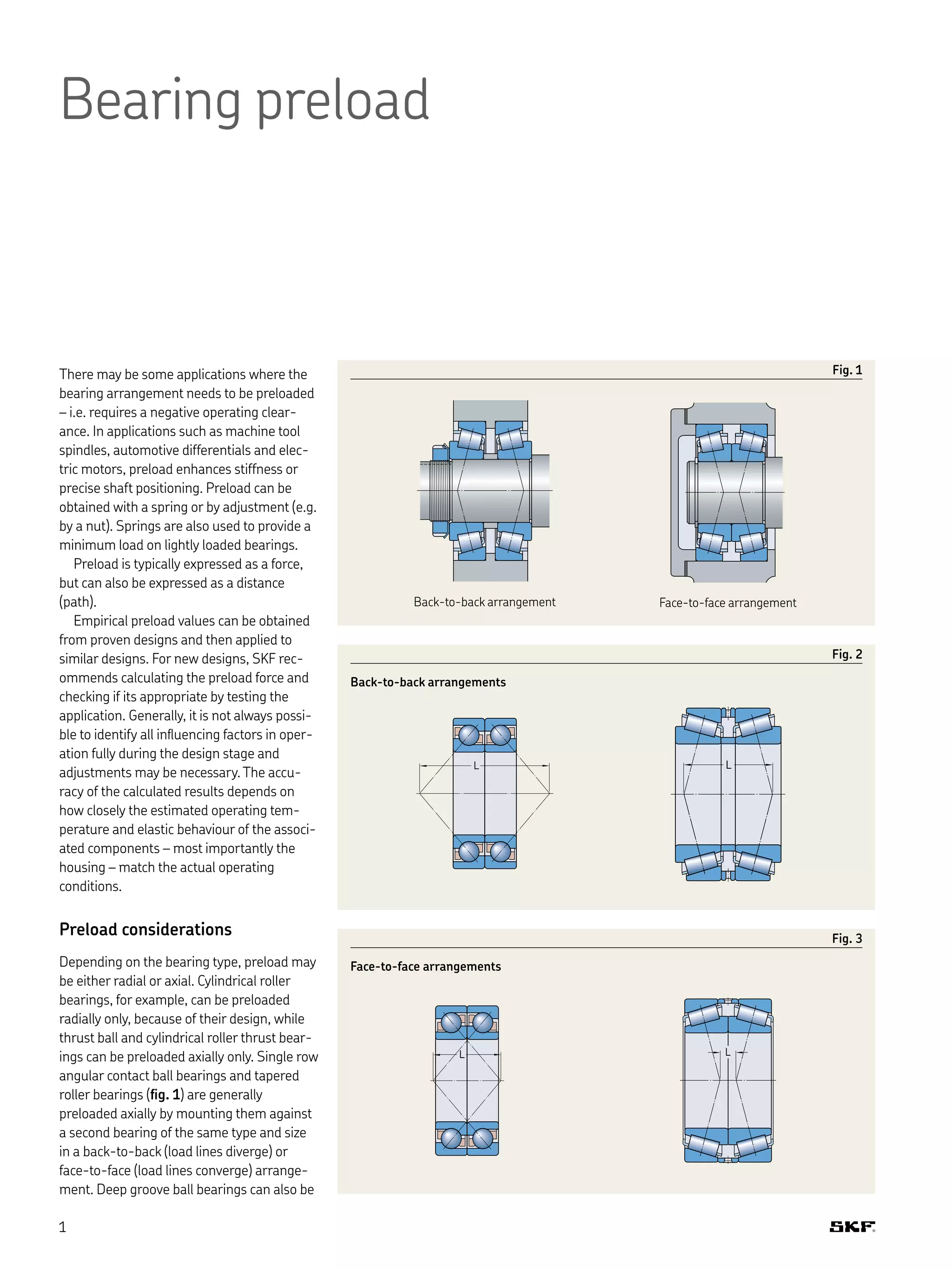
![preloaded axially – in this case, the bearings
have a greater radial internal clearance (C3
or C4) so that a contact angle is obtained.
For both tapered roller and angular con-
tact ball bearings, the distance L between
the pressure centres is longer when the
bearings are arranged back-to-back (ig. 2)
compared with bearings arranged face-to-
face (ig. 3).This means that bearings
arranged back-to-back can accommodate
relatively large tilting moments even if the
dis tance between the bearing centres is
relatively short.The radial loads and bearing
elastic displacements resulting from a
moment load are smaller for bearings
arranged back-to-back than when arranged
face-to-face.
If during operation the shaft temperature
is higher than the housing temperature, the
preload, which was adjusted at ambient
temperature during mounting, will change.
Depending on the distance between the
bearings and the type of arrangement (face-
to-face or back-to-back) the preload may
increase or decrease. In any case, thermal
expansion of the inner ring in the radial
direction leads to increase of the preload.
Thermal expansion in the axial direction
increases the preload when the bearings are
face-to-face, but is reduced for back-to-
back arrangements.
Depending on the distance between the
bearings, and provided the coeficient of
thermal expansion is the same for the bear-
ings and associated components, thermal
expansion in both the radial and axial
directions can cancel each other out so that
preload remains unchanged for back-to-
back arrangements independent of operating
temperature.
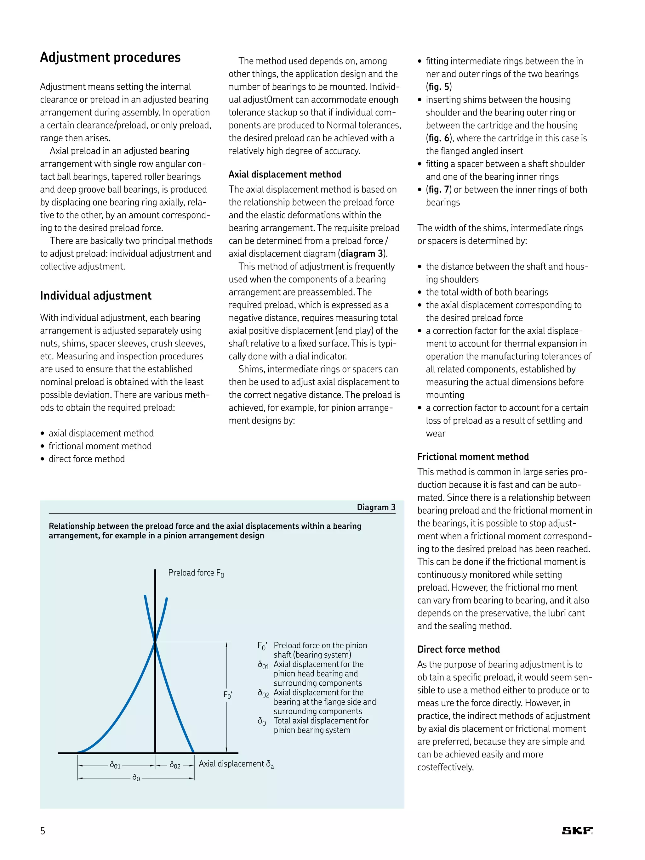
Effects of bearing preload
The primary beneits resulting from preload
include but are not limited to:
• enhanced stiffness
• reduced noise levels
• improved shaft guidance
• compensation for wear and settling
• extended bearing service life
Enhanced stiffness
Bearing stiffness [kN/mm] is deined as the
ratio of the force acting on the bearing to the
elastic deformation in the bearing.The elastic
deformation caused by a load in preloaded
bearings is smaller for a given load range
than for bearings that are not preloaded.
Reduced noise levels
As operating clearance in a bearing
decreases, rolling elements in the unloaded
zone become loaded, which reduces noise
levels in operation.
Improved shaft guidance
Preloaded bearings provide more accurate
shaft guidance because preload provides a
higher degree of stiffness, which limits the
ability of the shaft to delect under load. For
example, preloading the bearings in a differ-
ential results in increased stiffness, which
limits gear mesh variation.This minimizes
dynamic forces and reduces noise levels,
which can extend the service life of the
gears.
Compensation for wear and settling
Wear and settling between mating surfaces
in an adjusted bearing arrangement during
running-in leads to clearance.This can be
compensated for with preload.
Extended bearing service life
Provided the preload is properly set in an
adjusted bearing arrangement, the opera-
tional reliability can be enhanced, because of
a more favourable load distribution in the
bearings, which can extend bearing service
life. Setting the preload too hgh will overload
the bearing, lead to higher friction and nega-
tively inluence bearing life.
2](https://image.slidesharecdn.com/bearingpreloadtcm12-299896-180406100212/75/Bearing-preload-tcm-12-299896-2-2048.jpg)