Download to read offline


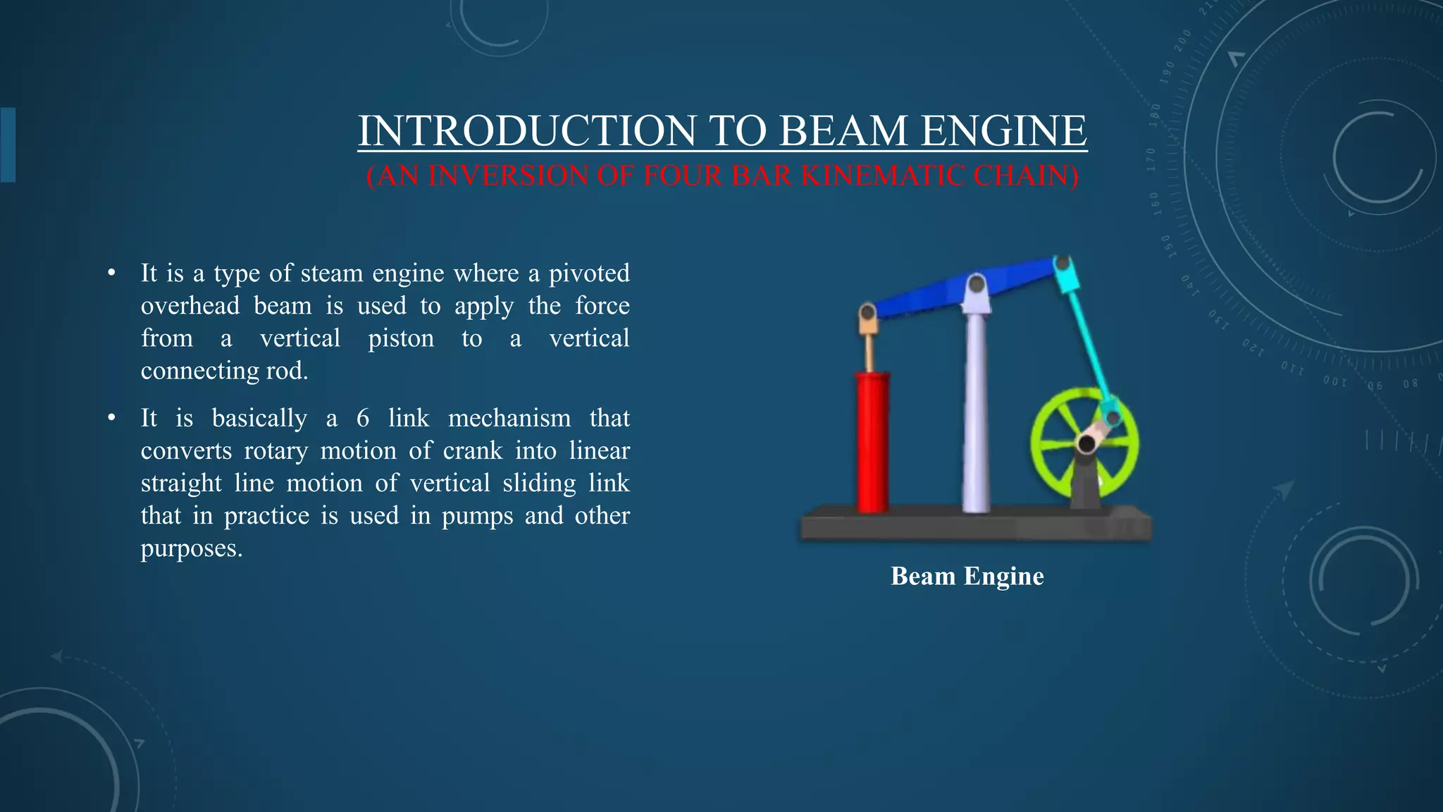


The document provides an overview of beam engine mechanisms, defining a mechanism as a group of linked components that transmit force and motion. It details the construction, working principles, advantages, disadvantages, and applications of the beam engine, which is a type of steam engine utilizing a pivoted beam to convert rotary motion into reciprocating motion. It also discusses the historical significance of the beam engine, particularly its invention by Thomas Newcomen in 1712 and its use in various applications such as water pumping and food processing.