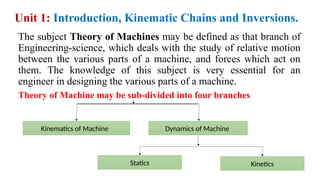
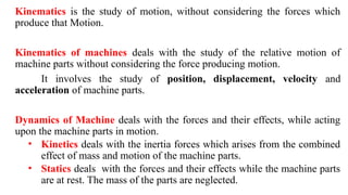
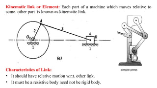
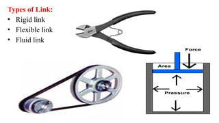
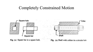
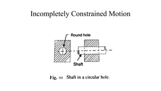
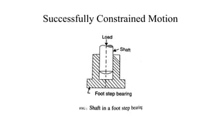
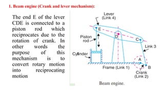
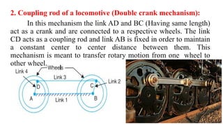
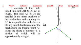
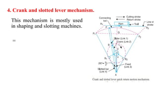
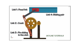
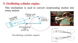
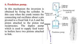
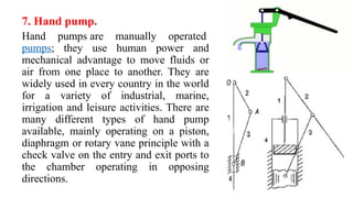
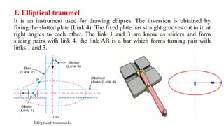
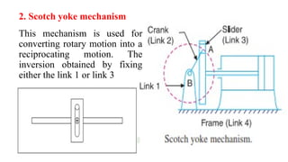
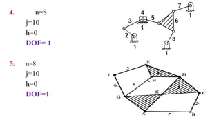
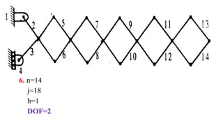
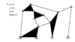
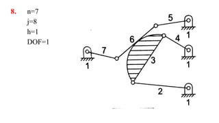
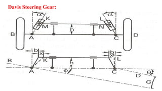
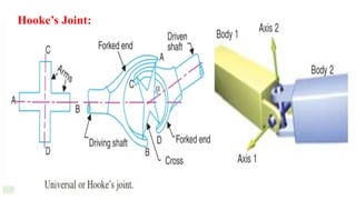
THEORY OF MACHINES
Sub Code :18MT45
Unit 1: Introduction, Kinematic Chains and Inversions.
The subject Theory of Machines may be defined as that branch of
Engineering-science, which deals with the study of relative motion
between the various parts of a machine, and forces which act on
them. The knowledge of this subject is very essential for an
engineer in designing the various parts of a machine.
Theory of Machine may be sub-divided into four branches
Kinematics of Machine
Statics Kinetics
Dynamics of Machine
Kinematics is the study of motion, without considering the forces which
produce that Motion.
Kinematics of machines deals with the study of the relative motion of
machine parts without considering the force producing motion.
It involves the study of position, displacement, velocity and
acceleration of machine parts.
Dynamics of Machine deals with the forces and their effects, while acting
upon the machine parts in motion.
• Kinetics deals with the inertia forces which arises from the combined
effect of mass and motion of the machine parts.
• Statics deals with the forces and their effects while the machine parts
are at rest. The mass of the parts are neglected.
Simple press
Kinematic link or Element: Each part of a machine which moves relative to
some other part is known as kinematic link.
Characteristics of Link:
• It should have relative motion w.r.t. other link.
• It must be a resistive body need not be rigid body.
Types of Link:
• Rigid link
• Flexible link
• Fluid link
Completely Constrained Motion
Incompletely Constrained Motion
Successfully Constrained Motion
Kinematic Pair: kinematic pair is defined as a joint of two or
more links having relative motion between them.
(I) Based on nature of contact between elements:
(a) Lower pair. If the joint by which two members are
connected has surface contact, the pair is known as lower pair.
Eg. Pin joints, shaft rotating in bush, slider in slider crank
mechanism.
b) Higher Pair: A higher pair is a kinematic pair in which
connection between two elements is only a point or line contact.
(II) Based on relative motion between pairing elements:
1.Revolute or Turning Pair (Hinged Joint)
2.Prismatic or Sliding Pair
3.Screw Pair
4.Rolling Pair
5.Spherical Pair
6.Planar Pair
(III) Based on type of closure
(a)Self closed pairs: Elements of
pairs held together mechanically
due to their geometry constitute a
closed pair. They are also called
form-closed or self-closed pair.
(b) Unclosed or force closed pair:
Elements of pairs held together by
the action of external forces
constitute unclosed or force closed
pair .Eg. Cam and follower.
Types of Constrained motions
(a) Completely constrained motion
(b) Incompletely constrained motion
(c) Successfully constrained motion
Kinematic chain
• When the kinematic pairs are coupled
in such a way that the last link is joined
to the first link to transmit definite
motion is called as kinematic chain
A kinematic chain is assembly in
which the relative motion is possible
and the motion of each relative to other
links is definite.
• If the links are connected in such a
way that no motion is possible, it
results in a locked chain or structure. Rear-window wiper
Conceptual design for an
exercise machine
Kinematic Joints
A joint is movable connection between links and allows
relative motion between the link
• Binary joint
• Ternary joint
• Quaternary joint
Mechanism
• When one of the links of a kinematic chain is fixed , the chain
is known as mechanism.
• A combination of number of bodies assembled in such a way
that the motion of one causes the constrained and predictable
motion of the others is known as mechanism.
Planar mechanisms: When all the links of a mechanism have
plane motion, it is called as a planar mechanism. All the links in
a planar mechanism move in planes parallel to the reference
MACHINE V/S STRUCTURE
MACHINE V/S MECHANISM
The parts of a machine move relative to
one another
Whereas the members of a structure do
not move relative to one another.
A machine transforms the available
energy into some useful work,
Whereas in a structure no energy is
transformed into useful work.
The links of a machine may transmit both
power and motion,
While the members of a structure
transmit forces only.
Machine is the combination of number of
such mechanisms used to carry out a
particular task.
Mechanism is a combination of various
links which are capable of having relative
motion with respect to one another.
Eg. Lathe, Shaper, Steam Engine… Eg. Type-writer, Clock work
Inversions of Mechanism:
• A mechanism is one in which one of the links of a kinematic chain
is fixed. Different mechanisms can be obtained by fixing different
links of the same kinematic chain.
• This method of obtaining different mechanisms by fixing
different links in a kinematic chain is known as inversion of the
mechanism.
Types of kinematic chains:
1. Four bar chain
2. Single slider crank chain.
3. Double slider crank chain.
Four-bar chain/ Quadric cycle
chain:
The simplest and basic kinematic
chain is four-bar chain. Its consists of
four links, each of them forms a
turning pair at A, B, C and D. The four
links may be different lengths.
According to Grashof’s law for a four
bar mechanism, the sum of shortest
and longest link lengths should not be
greater then the sum of links lengths of
other two if there is to be continuous
relative motion between the two links.
Inversions of four bar chain:
Though there are many inversions of the four bar chain, yet
the following are important from the subject point of view:
1.Beam engine (Crank and lever mechanism)
2.Coupling rod of a locomotive (Double crank mechanism)
3.Watt’s Indicator mechanism (Double lever mechanism)
1. Beam engine (Crank and lever mechanism):
The end E of the lever
CDE is connected to a
piston rod which
reciprocates due to the
rotation of crank. In
other words the
purpose of this
mechanism is to
convert rotary motion
into reciprocating
motion
2. Coupling rod of a locomotive (Double crank mechanism):
In this mechanism the link AD and BC (Having same length)
act as a crank and are connected to a respective wheels. The link
CD acts as a coupling rod and link AB is fixed in order to maintain
a constant center to center distance between them. This
mechanism is meant to transfer rotary motion from one wheel to
other wheel.
3. Watt’s Indicator mechanism (Double lever mechanism):
It consists of four link:
Fixed link, link AB & DE act as
levers. The links AB & DE are
parallel in the mean position of
the mechanism and coupling rod
BD is perpendicular to the levers.
On any small displacement of the
mechanism the tracing point ‘C’
traces the shape of number ‘8’ a
portion of which will be
approximately straight.
Inversions of single slider crank Chain:
1. Reciprocating engine mechanism.
2. Rotary I C engine(Gnome engine)..
3. Whitworth quick return motion mechanism.
4. Crank and slotted lever mechanism.
5. Oscillating cylinder engine.
6. Bull engine mechanism or Pendulum pump.
7. Hand pump.
1. Reciprocating engine mechanism
The single slider crank chain is a modification of basic 4-bar chain. Its
consists of one sliding pair and three turning pairs. This type of
mechanism converts rotary motion in reciprocating motion and vive
versa
2.Rotary I C engine(Gnome engine).
Sometimes back rotary internal
combustion engines were used in
aviation. But now a days gas
turbines are used in its place. It
consists of 7 cylinders in one plane
and all revolves about fixed centre
D. In this mechanism, when the
connecting rod rotates, the piston
reciprocates inside the cylinder.
3.Whitworth quick return motion mechanism.
This mechanism is mostly used in shaping and slotting
machines. =
4. Crank and slotted lever mechanism.
This mechanism is mostly used
in shaping and slotting machines.
=
5. Oscillating cylinder engine.
This mechanism is used to convert reciprocating motion into
rotary motion
6. Pendulum pump.
In this mechanism the inversion is
obtained by fixing the cylinder. In
this case when the crank rotates the
connecting rod oscillates about a pin
pivoted to a fixed link 4 at A and the
piston attached to the piston rod
reciprocates. The duplex pump
which is used to supply feed water
to boilers have two pistons attached
to link.
7. Hand pump.
Hand pumps are manually operated
pumps; they use human power and
mechanical advantage to move fluids or
air from one place to another. They are
widely used in every country in the world
for a variety of industrial, marine,
irrigation and leisure activities. There are
many different types of hand pump
available, mainly operating on a piston,
diaphragm or rotary vane principle with a
check valve on the entry and exit ports to
the chamber operating in opposing
directions.
Inversions of Double slider crank chain.
1. Elliptical trammel
2. Scotch yoke mechanism
3. Oldham’s coupling
1. Elliptical trammel
It is an instrument used for drawing ellipses. The inversion is obtained by
fixing the slotted plate (Link 4). The fixed plate has straight grooves cut in it, at
right angles to each other. The link 1 and 3 are know as sliders and form
sliding pairs with link 4. the link AB is a bar which forms turning pair with
links 1 and 3.
2. Scotch yoke mechanism
This mechanism is used for
converting rotary motion into a
reciprocating motion. The
inversion obtained by fixing
either the link 1 or link 3
3. Oldham’s coupling
An Oldham’s coupling is used for connecting two parallel shafts whose
axes are at a small distance apart. The shafts are coupled in such a wat
that is one shafts rotates, the other shaft also rotates at the same speed.
Degrees of freedom & Mobility of a mechanism: Minimum
number of independent parameters required to specify the
location of every link within mechanism. Mobility of
mechanism defines the number of DOF.
Grubler’s criterion:
Number of degrees of freedom of a mechanism is given by
DOF= 3(n-1)-2j-h.
Where, DOF= Degrees of freedom
n= Number of links in the mechanism.
j= Number of lower pairs= n+l-1
l= Number of loops
h = Number of higher pairs
Examples on DOF:
1. n=4
j=4
h=0
DOF=1
2. n= 8
j=10
h=0
DOF=1
3. Case i: Follower will have rolling and sliding
n=4
j=3
h=1
DOF=2
Case ii: If link 4&3 constitute one link
n=3
j=2
h=1
DOF=1
Case iii: If the contact between cam and follower is pure rolling (No Sliding)
n=4
j=4
h=0
DOF=1
4. n=8
j=10
h=0
DOF= 1
5. n=8
j=10
h=0
DOF=1
6. n=14
j=18
h=1
DOF=2
7. n=12
j=16
h=0
DOF=1
8. n=7
j=8
h=1
DOF=1
End….!
Unit 2: Mechanisms
Quick return motion mechanism
1. Whitworth quick return mechanism
2. Drag link mechanism
3. Crank and slotted lever mechanism
Drag link mechanism:
Straight line motion mechanism
1. Exact straight line mechanism
1. Peaucellier mechanism
2. Hart mechanism
3. Scott-Russell mechanism
2. Approximate straight line mechanism
1. Watt mechanism
2. Robert’s mechanism
Condition for Exact straight line motion mechanism:
AP=
Peaucellier’s Mechanism:
Its consists of 8 links
AC=CB=BD=DA; CO=OD
The product of OB.OA is constant,
hence the point B traces a straight
path perpendicular to the diameter
OP
Robert’s Mechanism:
It’s a 4-bar chain mechanism,
which in its mean position, has
the form of trapezium. The link
OA & O1B are of equal length. A
bar PQ is rigidly attached to the
link AB at its middle point P, if
the mechanism is displaced as
shown by the dotted lines, the
point Q will trace out an
approximately straight line
Intermittent Motion Mechanism
(a) Ratchet & Pawl Mechanism
This mechanism is used in
producing intermittent rotary motion
from an oscillating or reciprocating
motion members.
(b) Geneva Mechanism
This mechanism is used in
preventing over winding of main
springs in clocks and watches,
feeding of film roll in early motion-
picture projectors and indexing of a
work table on a machine tool.
Toggle Mechanism:
Pantograph:
A pantograph is a mechanical
linkage connected in a manner based
on parallelograms so that the
movement of one pen, in tracing an
image, produces identical movements
in a second pen.
Condition for correct Steering in motor car:
Let a – Wheel track
b = Wheel base
c = Distance b/w A & B
Now from triangle IBP
cotθ= BP/IP
and from triangle IAP
Ackermann Steering Gear Mechanism:
Davis Steering Gear:
Hooke’s Joint:

Module 1 Introductihhhhhfevjigcbnnjon to TOM.pptx

  • 1.
  • 2.
    Unit 1: Introduction,Kinematic Chains and Inversions. The subject Theory of Machines may be defined as that branch of Engineering-science, which deals with the study of relative motion between the various parts of a machine, and forces which act on them. The knowledge of this subject is very essential for an engineer in designing the various parts of a machine. Theory of Machine may be sub-divided into four branches Kinematics of Machine Statics Kinetics Dynamics of Machine
  • 3.
    Kinematics is thestudy of motion, without considering the forces which produce that Motion. Kinematics of machines deals with the study of the relative motion of machine parts without considering the force producing motion. It involves the study of position, displacement, velocity and acceleration of machine parts. Dynamics of Machine deals with the forces and their effects, while acting upon the machine parts in motion. • Kinetics deals with the inertia forces which arises from the combined effect of mass and motion of the machine parts. • Statics deals with the forces and their effects while the machine parts are at rest. The mass of the parts are neglected.
  • 4.
    Simple press Kinematic linkor Element: Each part of a machine which moves relative to some other part is known as kinematic link. Characteristics of Link: • It should have relative motion w.r.t. other link. • It must be a resistive body need not be rigid body.
  • 5.
    Types of Link: •Rigid link • Flexible link • Fluid link
  • 6.
  • 7.
  • 8.
  • 9.
    Kinematic Pair: kinematicpair is defined as a joint of two or more links having relative motion between them. (I) Based on nature of contact between elements: (a) Lower pair. If the joint by which two members are connected has surface contact, the pair is known as lower pair. Eg. Pin joints, shaft rotating in bush, slider in slider crank mechanism.
  • 10.
    b) Higher Pair:A higher pair is a kinematic pair in which connection between two elements is only a point or line contact.
  • 11.
    (II) Based onrelative motion between pairing elements: 1.Revolute or Turning Pair (Hinged Joint) 2.Prismatic or Sliding Pair 3.Screw Pair 4.Rolling Pair 5.Spherical Pair 6.Planar Pair
  • 12.
    (III) Based ontype of closure (a)Self closed pairs: Elements of pairs held together mechanically due to their geometry constitute a closed pair. They are also called form-closed or self-closed pair. (b) Unclosed or force closed pair: Elements of pairs held together by the action of external forces constitute unclosed or force closed pair .Eg. Cam and follower.
  • 13.
    Types of Constrainedmotions (a) Completely constrained motion (b) Incompletely constrained motion (c) Successfully constrained motion
  • 14.
    Kinematic chain • Whenthe kinematic pairs are coupled in such a way that the last link is joined to the first link to transmit definite motion is called as kinematic chain A kinematic chain is assembly in which the relative motion is possible and the motion of each relative to other links is definite. • If the links are connected in such a way that no motion is possible, it results in a locked chain or structure. Rear-window wiper Conceptual design for an exercise machine
  • 15.
    Kinematic Joints A jointis movable connection between links and allows relative motion between the link • Binary joint • Ternary joint • Quaternary joint
  • 16.
    Mechanism • When oneof the links of a kinematic chain is fixed , the chain is known as mechanism. • A combination of number of bodies assembled in such a way that the motion of one causes the constrained and predictable motion of the others is known as mechanism. Planar mechanisms: When all the links of a mechanism have plane motion, it is called as a planar mechanism. All the links in a planar mechanism move in planes parallel to the reference
  • 17.
    MACHINE V/S STRUCTURE MACHINEV/S MECHANISM The parts of a machine move relative to one another Whereas the members of a structure do not move relative to one another. A machine transforms the available energy into some useful work, Whereas in a structure no energy is transformed into useful work. The links of a machine may transmit both power and motion, While the members of a structure transmit forces only. Machine is the combination of number of such mechanisms used to carry out a particular task. Mechanism is a combination of various links which are capable of having relative motion with respect to one another. Eg. Lathe, Shaper, Steam Engine… Eg. Type-writer, Clock work
  • 18.
    Inversions of Mechanism: •A mechanism is one in which one of the links of a kinematic chain is fixed. Different mechanisms can be obtained by fixing different links of the same kinematic chain. • This method of obtaining different mechanisms by fixing different links in a kinematic chain is known as inversion of the mechanism. Types of kinematic chains: 1. Four bar chain 2. Single slider crank chain. 3. Double slider crank chain.
  • 19.
    Four-bar chain/ Quadriccycle chain: The simplest and basic kinematic chain is four-bar chain. Its consists of four links, each of them forms a turning pair at A, B, C and D. The four links may be different lengths. According to Grashof’s law for a four bar mechanism, the sum of shortest and longest link lengths should not be greater then the sum of links lengths of other two if there is to be continuous relative motion between the two links.
  • 20.
    Inversions of fourbar chain: Though there are many inversions of the four bar chain, yet the following are important from the subject point of view: 1.Beam engine (Crank and lever mechanism) 2.Coupling rod of a locomotive (Double crank mechanism) 3.Watt’s Indicator mechanism (Double lever mechanism)
  • 21.
    1. Beam engine(Crank and lever mechanism): The end E of the lever CDE is connected to a piston rod which reciprocates due to the rotation of crank. In other words the purpose of this mechanism is to convert rotary motion into reciprocating motion
  • 22.
    2. Coupling rodof a locomotive (Double crank mechanism): In this mechanism the link AD and BC (Having same length) act as a crank and are connected to a respective wheels. The link CD acts as a coupling rod and link AB is fixed in order to maintain a constant center to center distance between them. This mechanism is meant to transfer rotary motion from one wheel to other wheel.
  • 23.
    3. Watt’s Indicatormechanism (Double lever mechanism): It consists of four link: Fixed link, link AB & DE act as levers. The links AB & DE are parallel in the mean position of the mechanism and coupling rod BD is perpendicular to the levers. On any small displacement of the mechanism the tracing point ‘C’ traces the shape of number ‘8’ a portion of which will be approximately straight.
  • 24.
    Inversions of singleslider crank Chain: 1. Reciprocating engine mechanism. 2. Rotary I C engine(Gnome engine).. 3. Whitworth quick return motion mechanism. 4. Crank and slotted lever mechanism. 5. Oscillating cylinder engine. 6. Bull engine mechanism or Pendulum pump. 7. Hand pump.
  • 25.
    1. Reciprocating enginemechanism The single slider crank chain is a modification of basic 4-bar chain. Its consists of one sliding pair and three turning pairs. This type of mechanism converts rotary motion in reciprocating motion and vive versa
  • 26.
    2.Rotary I Cengine(Gnome engine). Sometimes back rotary internal combustion engines were used in aviation. But now a days gas turbines are used in its place. It consists of 7 cylinders in one plane and all revolves about fixed centre D. In this mechanism, when the connecting rod rotates, the piston reciprocates inside the cylinder.
  • 27.
    3.Whitworth quick returnmotion mechanism. This mechanism is mostly used in shaping and slotting machines. =
  • 29.
    4. Crank andslotted lever mechanism. This mechanism is mostly used in shaping and slotting machines. =
  • 31.
    5. Oscillating cylinderengine. This mechanism is used to convert reciprocating motion into rotary motion
  • 32.
    6. Pendulum pump. Inthis mechanism the inversion is obtained by fixing the cylinder. In this case when the crank rotates the connecting rod oscillates about a pin pivoted to a fixed link 4 at A and the piston attached to the piston rod reciprocates. The duplex pump which is used to supply feed water to boilers have two pistons attached to link.
  • 33.
    7. Hand pump. Handpumps are manually operated pumps; they use human power and mechanical advantage to move fluids or air from one place to another. They are widely used in every country in the world for a variety of industrial, marine, irrigation and leisure activities. There are many different types of hand pump available, mainly operating on a piston, diaphragm or rotary vane principle with a check valve on the entry and exit ports to the chamber operating in opposing directions.
  • 34.
    Inversions of Doubleslider crank chain. 1. Elliptical trammel 2. Scotch yoke mechanism 3. Oldham’s coupling
  • 35.
    1. Elliptical trammel Itis an instrument used for drawing ellipses. The inversion is obtained by fixing the slotted plate (Link 4). The fixed plate has straight grooves cut in it, at right angles to each other. The link 1 and 3 are know as sliders and form sliding pairs with link 4. the link AB is a bar which forms turning pair with links 1 and 3.
  • 36.
    2. Scotch yokemechanism This mechanism is used for converting rotary motion into a reciprocating motion. The inversion obtained by fixing either the link 1 or link 3
  • 37.
    3. Oldham’s coupling AnOldham’s coupling is used for connecting two parallel shafts whose axes are at a small distance apart. The shafts are coupled in such a wat that is one shafts rotates, the other shaft also rotates at the same speed.
  • 38.
    Degrees of freedom& Mobility of a mechanism: Minimum number of independent parameters required to specify the location of every link within mechanism. Mobility of mechanism defines the number of DOF. Grubler’s criterion: Number of degrees of freedom of a mechanism is given by DOF= 3(n-1)-2j-h. Where, DOF= Degrees of freedom n= Number of links in the mechanism. j= Number of lower pairs= n+l-1 l= Number of loops h = Number of higher pairs
  • 39.
    Examples on DOF: 1.n=4 j=4 h=0 DOF=1 2. n= 8 j=10 h=0 DOF=1
  • 40.
    3. Case i:Follower will have rolling and sliding n=4 j=3 h=1 DOF=2 Case ii: If link 4&3 constitute one link n=3 j=2 h=1 DOF=1 Case iii: If the contact between cam and follower is pure rolling (No Sliding) n=4 j=4 h=0 DOF=1
  • 41.
    4. n=8 j=10 h=0 DOF= 1 5.n=8 j=10 h=0 DOF=1
  • 42.
  • 43.
  • 44.
  • 45.
  • 46.
  • 47.
    Quick return motionmechanism 1. Whitworth quick return mechanism 2. Drag link mechanism 3. Crank and slotted lever mechanism Drag link mechanism:
  • 48.
    Straight line motionmechanism 1. Exact straight line mechanism 1. Peaucellier mechanism 2. Hart mechanism 3. Scott-Russell mechanism 2. Approximate straight line mechanism 1. Watt mechanism 2. Robert’s mechanism Condition for Exact straight line motion mechanism: AP=
  • 49.
    Peaucellier’s Mechanism: Its consistsof 8 links AC=CB=BD=DA; CO=OD The product of OB.OA is constant, hence the point B traces a straight path perpendicular to the diameter OP
  • 50.
    Robert’s Mechanism: It’s a4-bar chain mechanism, which in its mean position, has the form of trapezium. The link OA & O1B are of equal length. A bar PQ is rigidly attached to the link AB at its middle point P, if the mechanism is displaced as shown by the dotted lines, the point Q will trace out an approximately straight line
  • 52.
    Intermittent Motion Mechanism (a)Ratchet & Pawl Mechanism This mechanism is used in producing intermittent rotary motion from an oscillating or reciprocating motion members.
  • 53.
    (b) Geneva Mechanism Thismechanism is used in preventing over winding of main springs in clocks and watches, feeding of film roll in early motion- picture projectors and indexing of a work table on a machine tool.
  • 54.
  • 55.
    Pantograph: A pantograph isa mechanical linkage connected in a manner based on parallelograms so that the movement of one pen, in tracing an image, produces identical movements in a second pen.
  • 56.
    Condition for correctSteering in motor car: Let a – Wheel track b = Wheel base c = Distance b/w A & B Now from triangle IBP cotθ= BP/IP and from triangle IAP
  • 57.
  • 58.
  • 59.