This document provides an overview of the course ME3491 – Theory of Machines taught by Mr. M. Dhanenthiran. It discusses the following key topics:
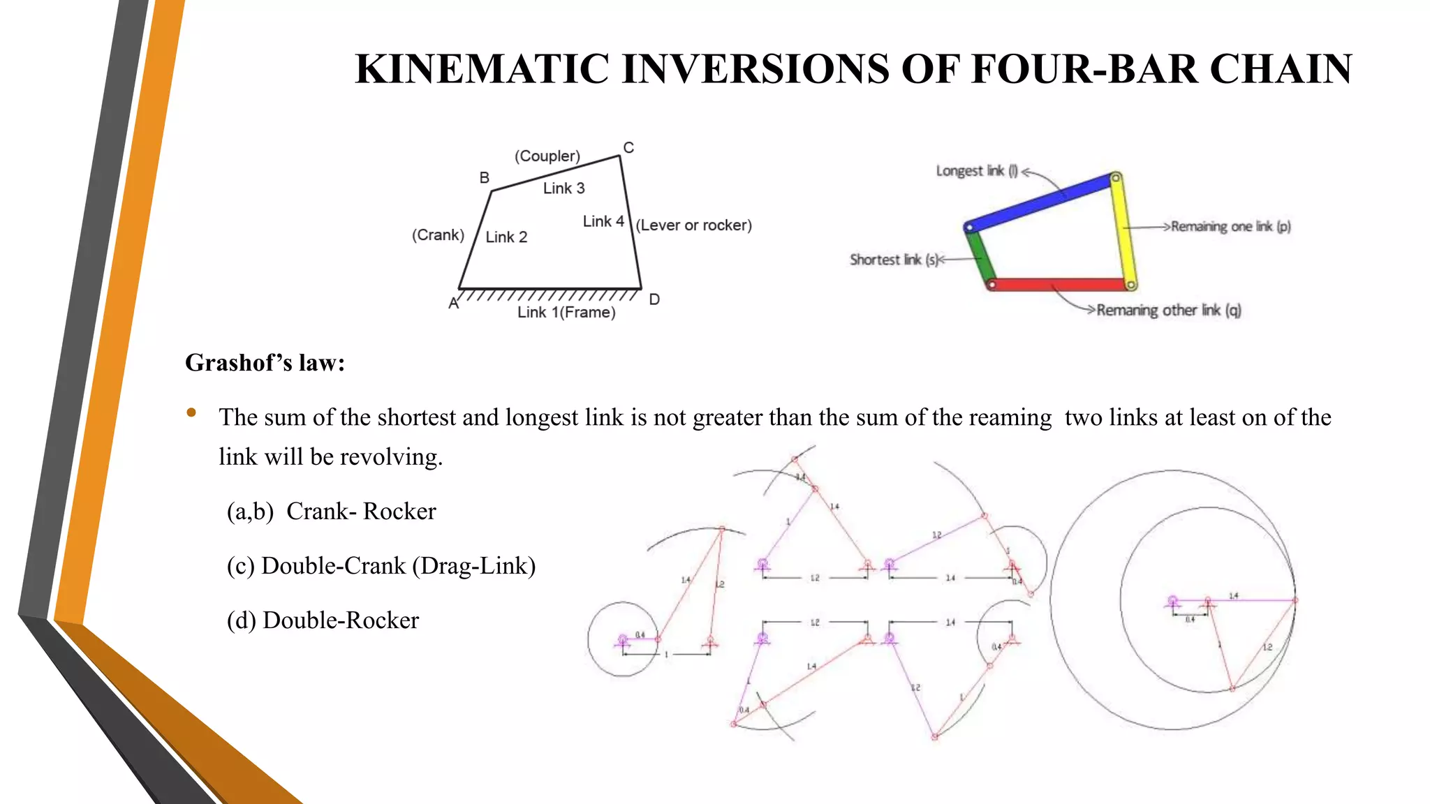
1. The course covers kinematics of mechanisms including terminology, kinematic inversions of 4-bar and slide crank chains, velocity/acceleration polygons, analytical and computer methods, and cam classifications.
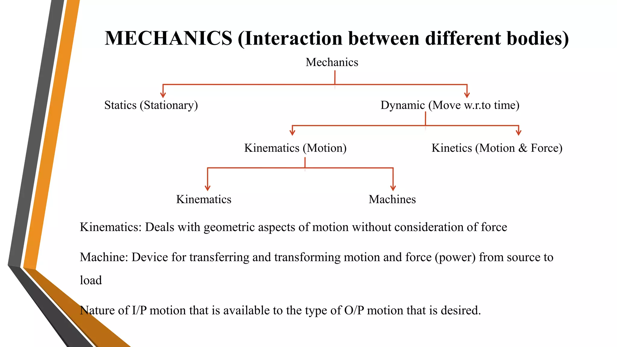
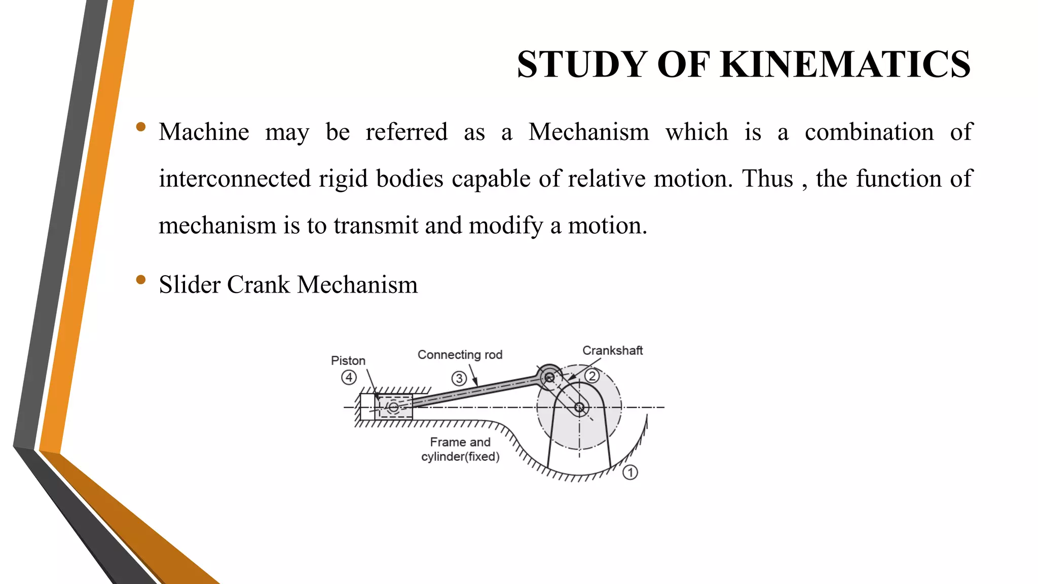
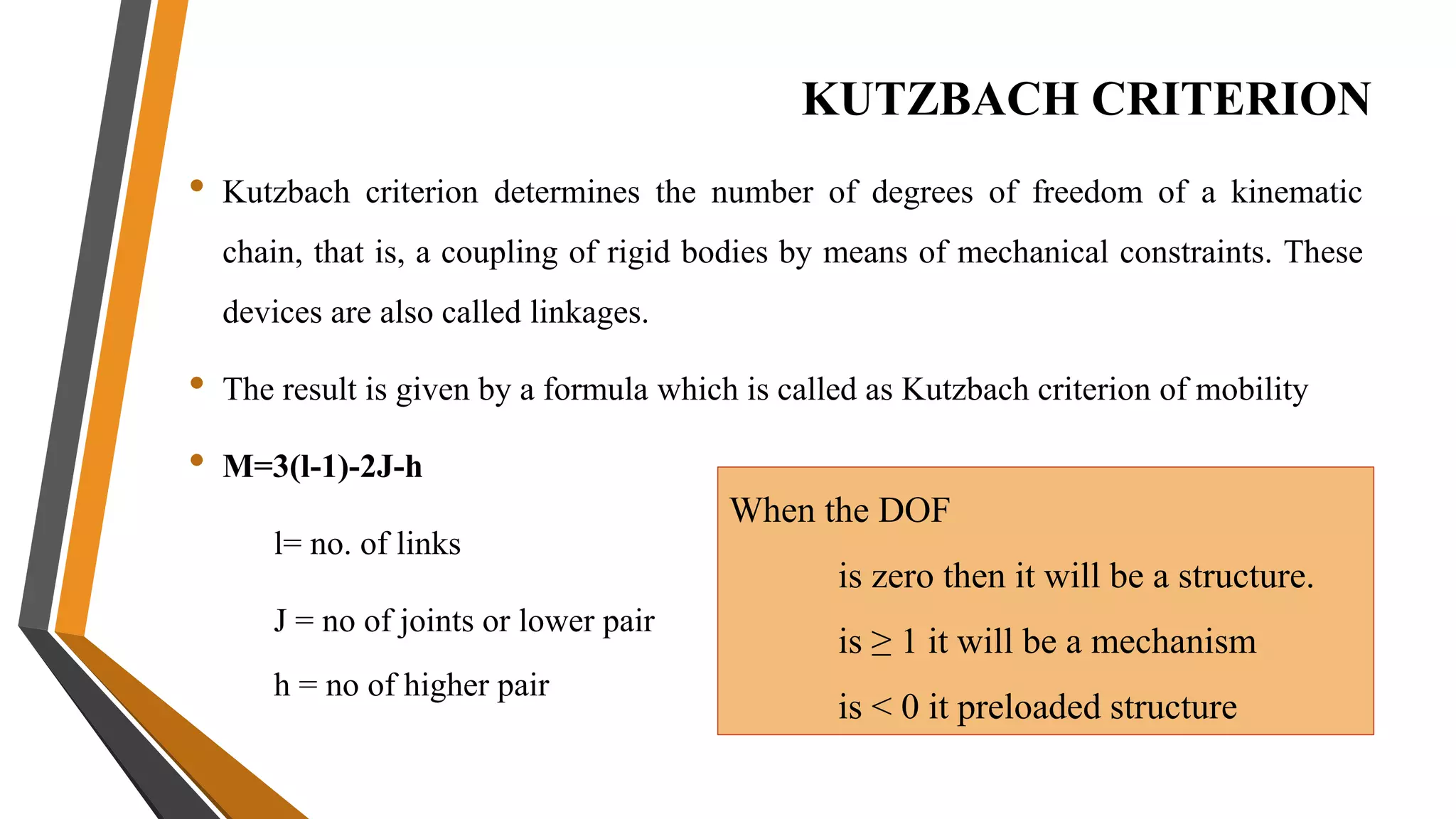
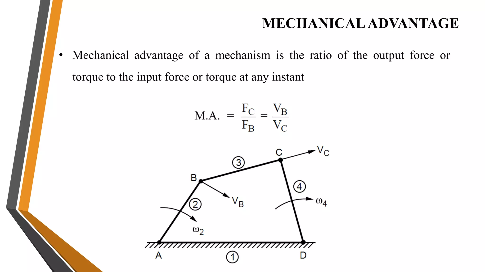
2. Theory of machines is the applied science used to understand relative motion and forces between machine parts. It involves kinematic and kinetic analysis as well as mechanism synthesis.
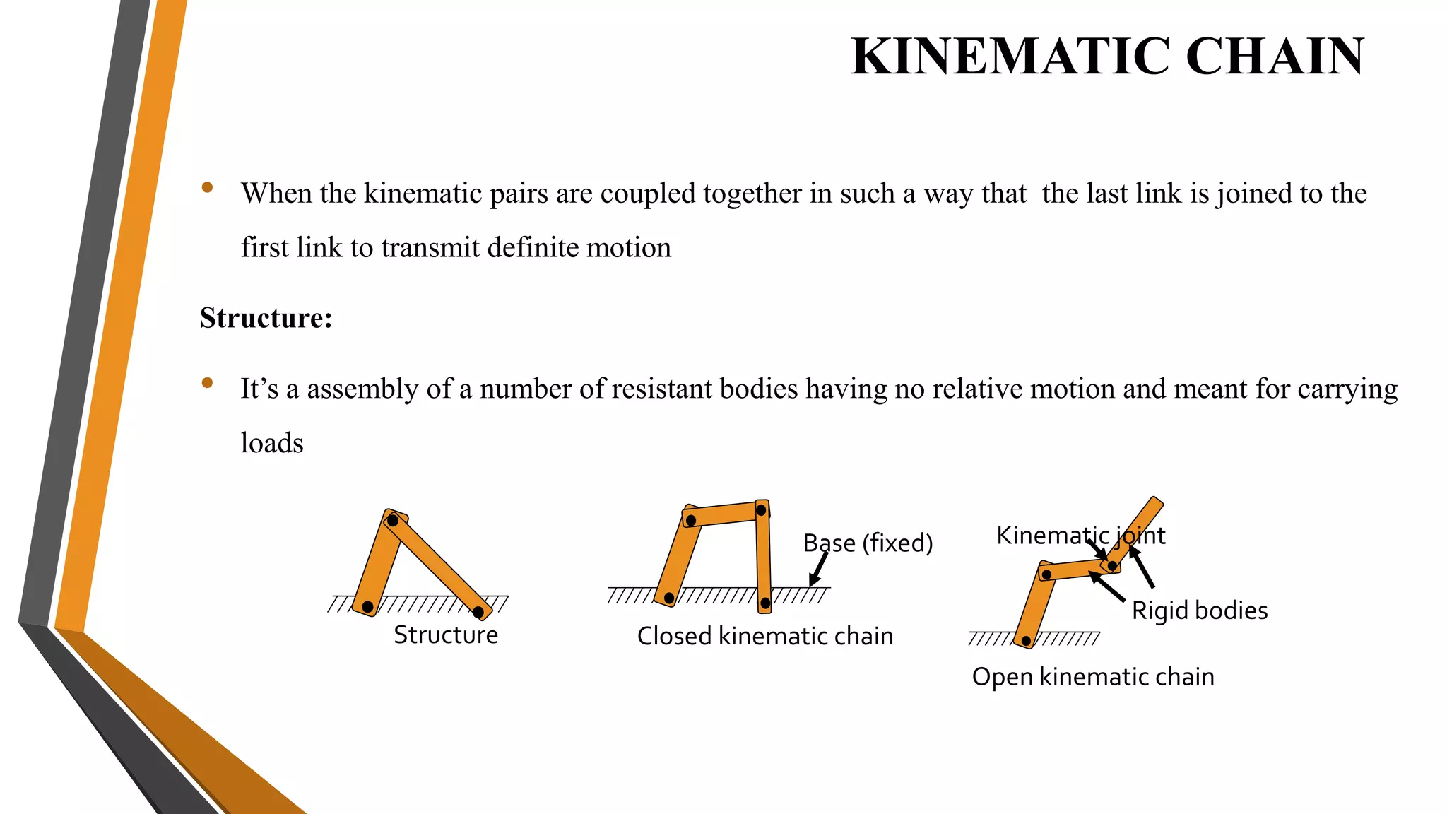
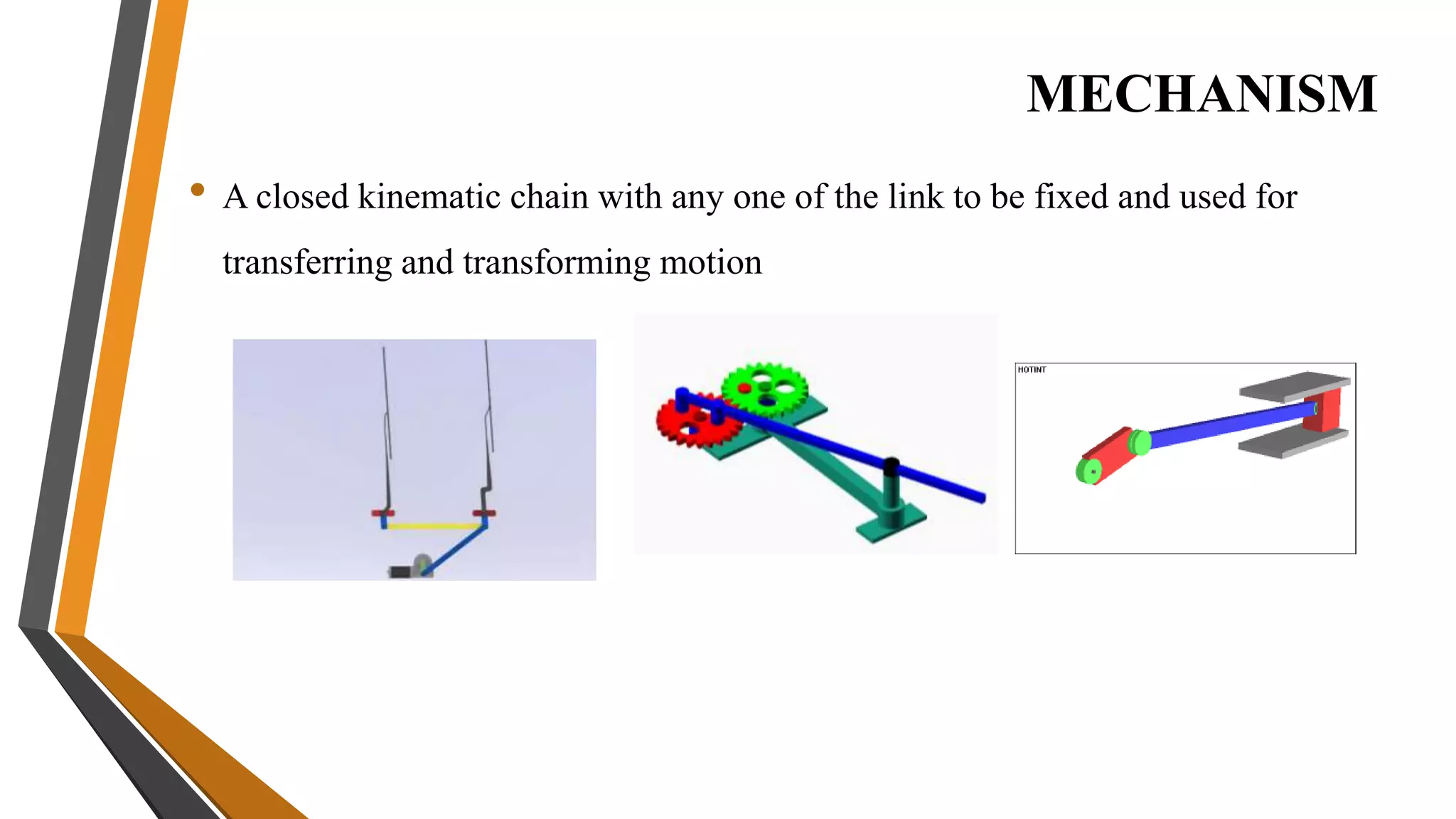
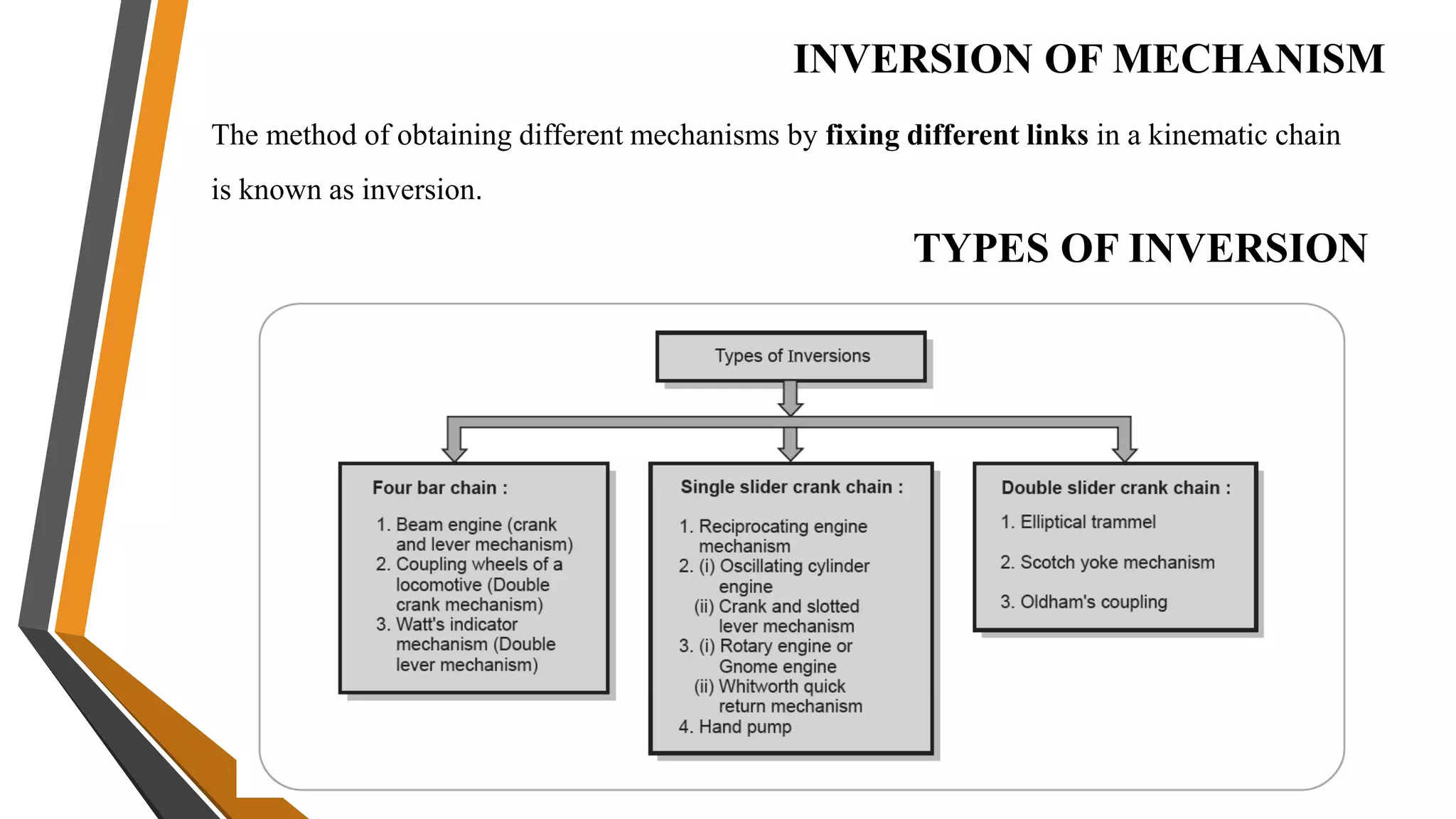
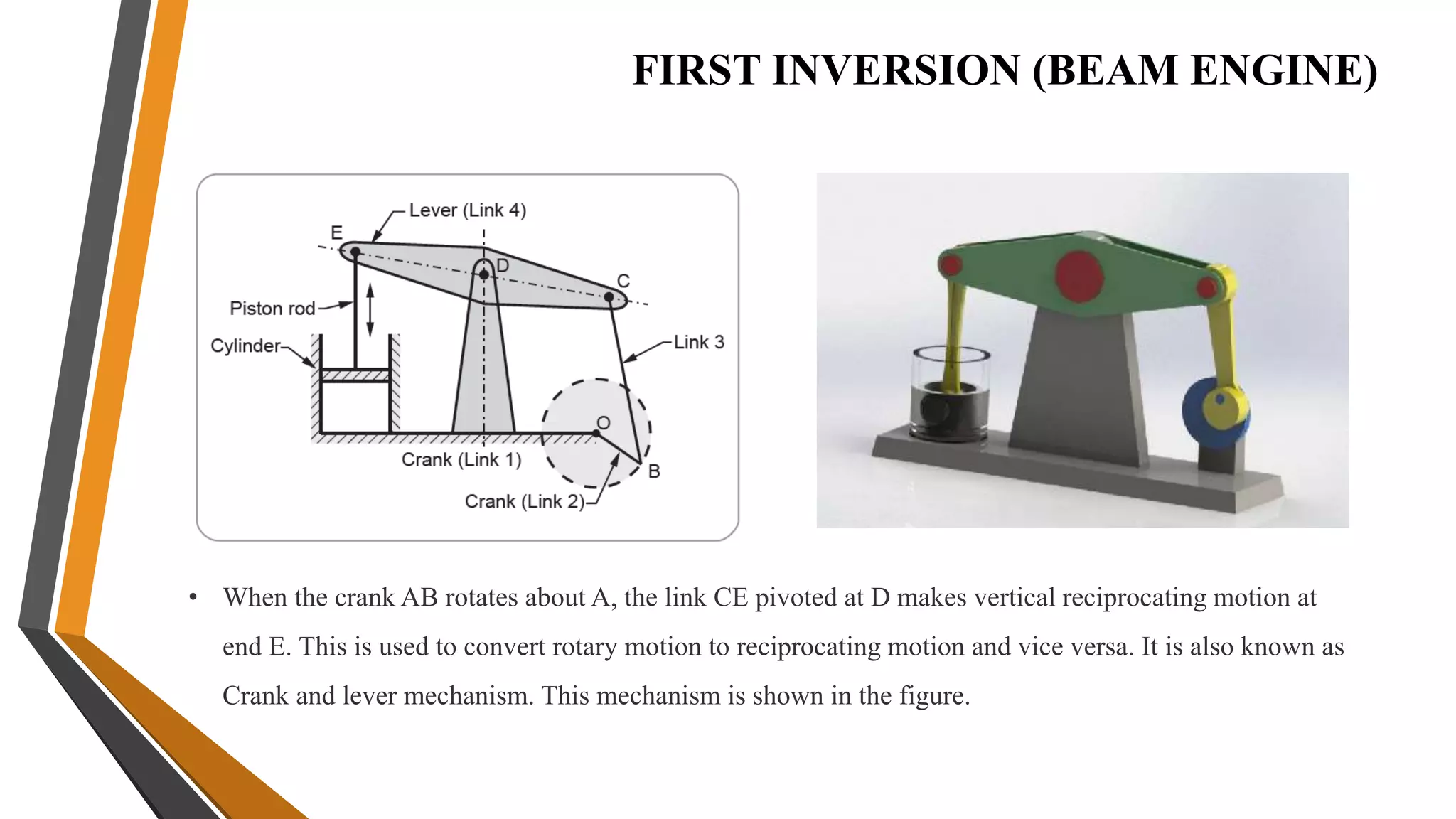
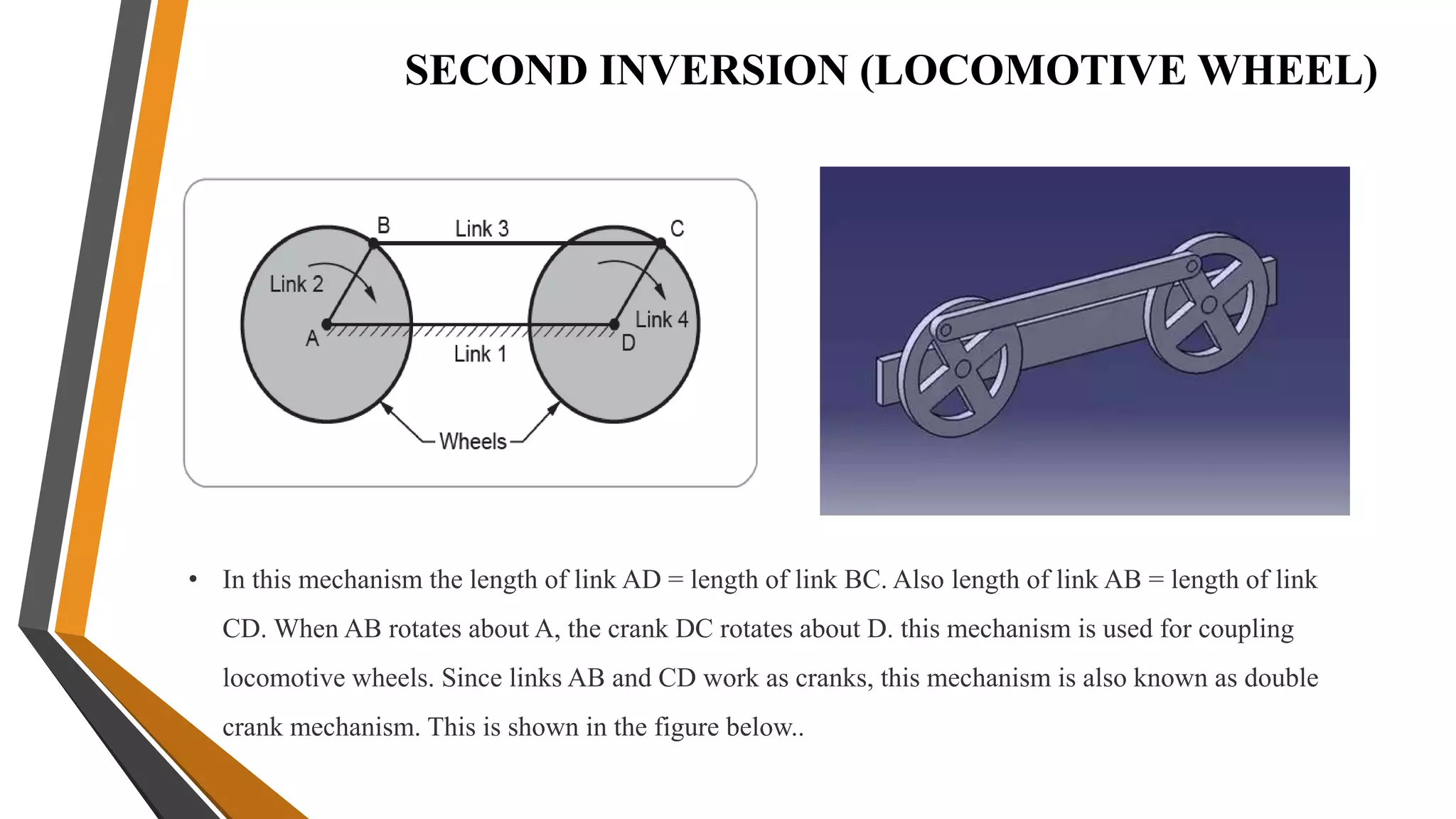
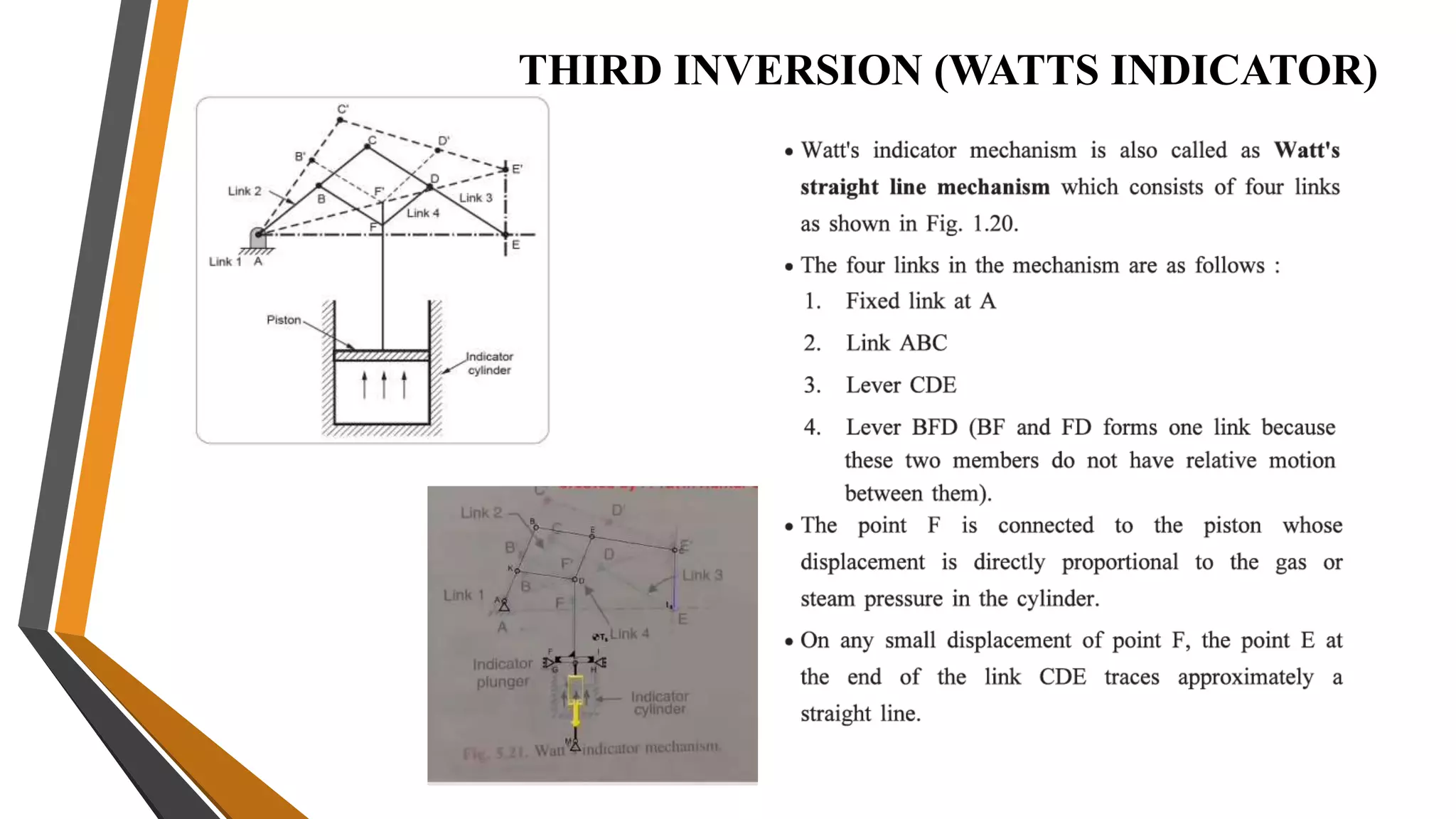
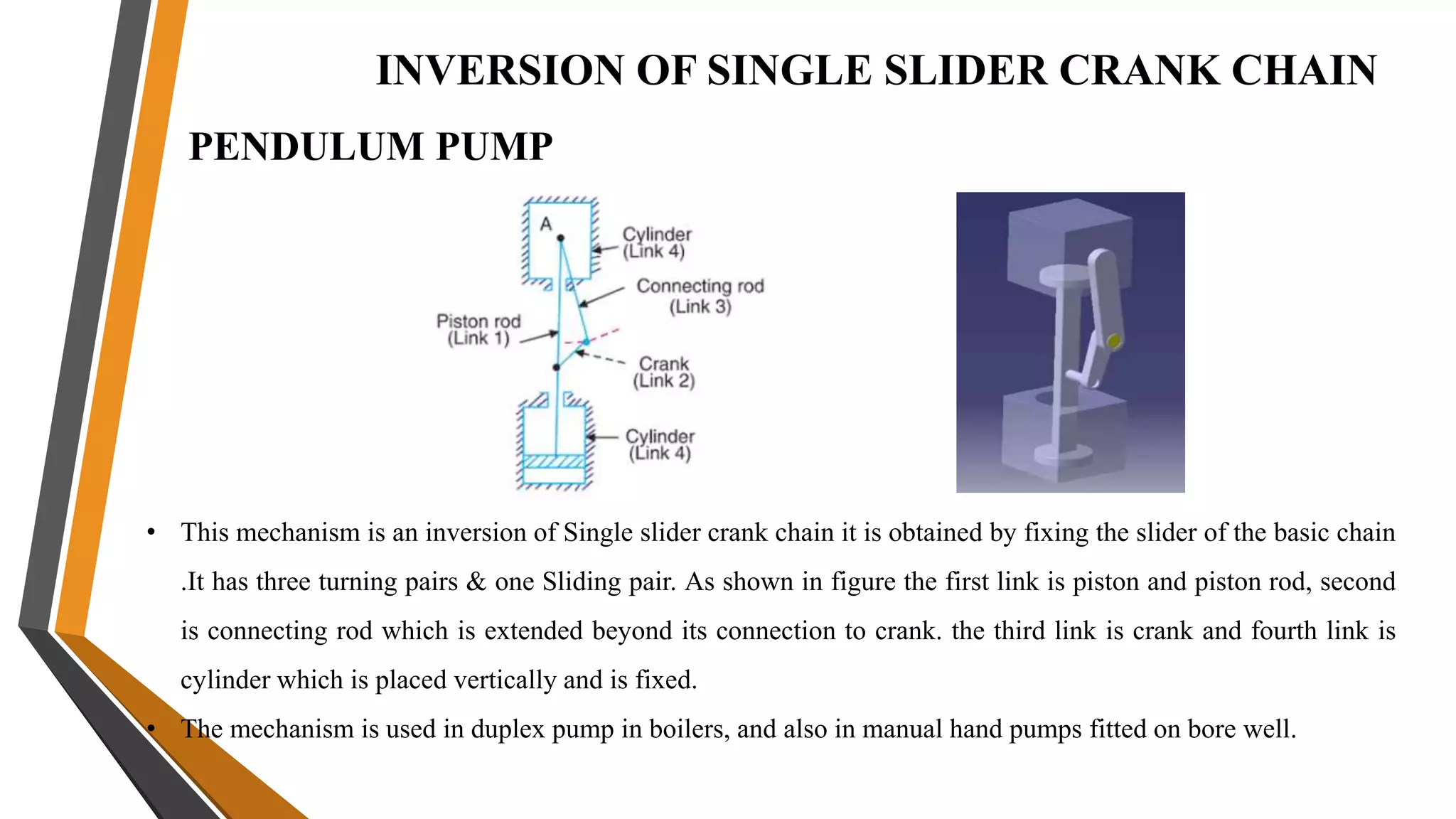
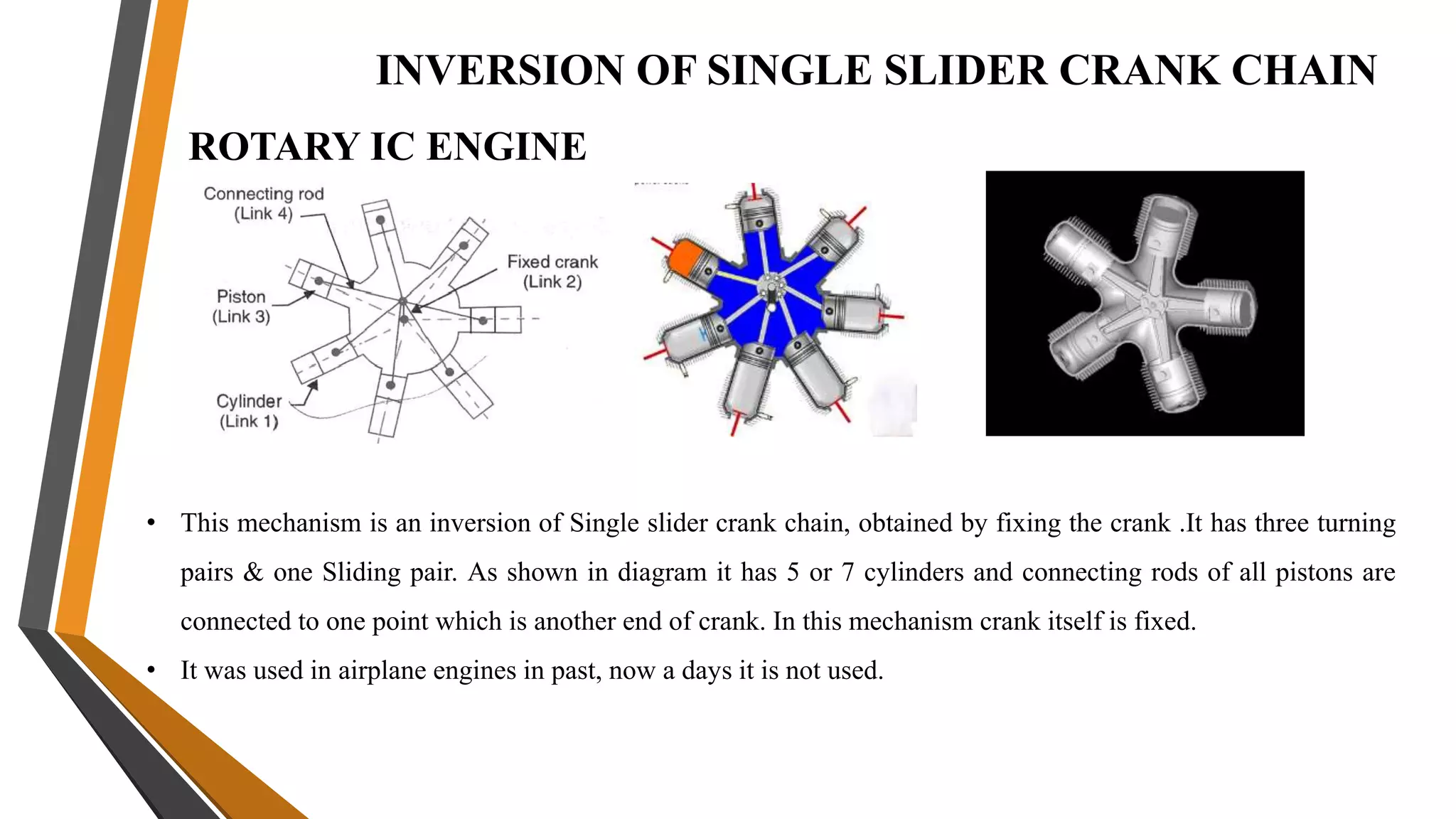
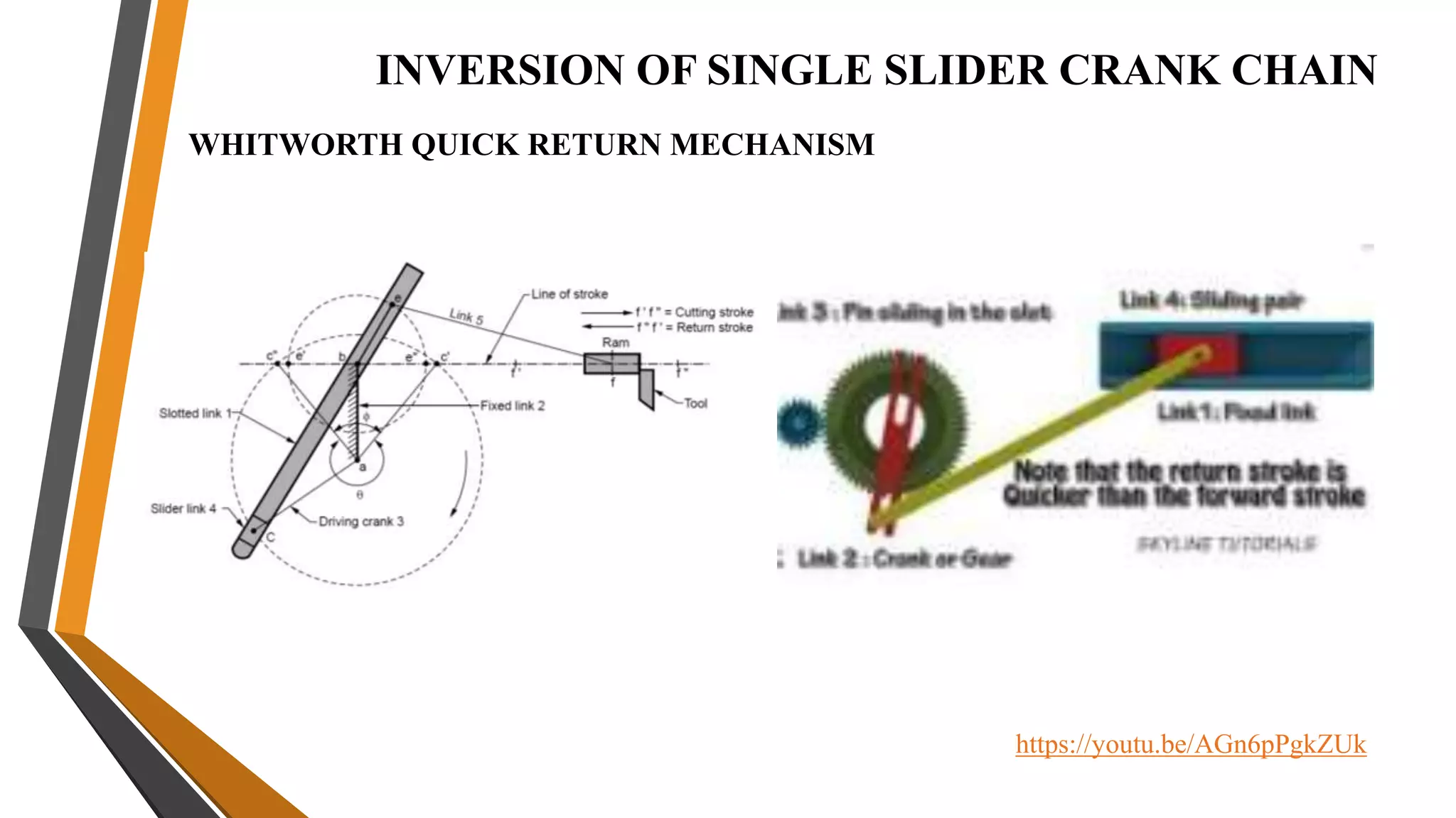
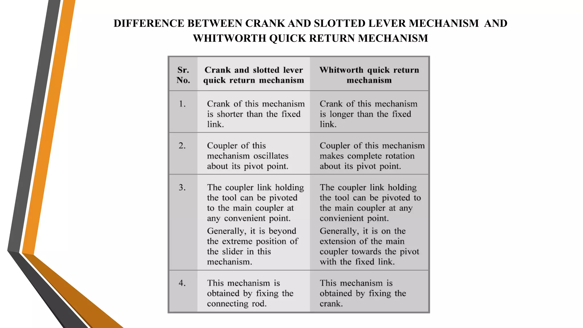
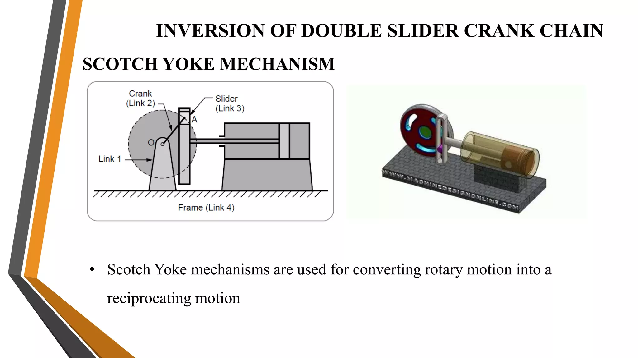
3. Mechanisms are combinations of rigid bodies that transmit and modify motion. Examples covered include slider crank, inversions of single/double slider crank chains