Download to read offline
![International Journal of Modern Engineering Research (IJMER)
www.ijmer.com Vol.3, Issue.2, March-April. 2013 pp-773-778 ISSN: 2249-6645
Enhancement of Power Quality in Thirty Bus System Using
ZSI Based STATCOM
N. Usha, 1 M.Vijaya Kumar2
1
Research scholar, JNTUA, Anantapur, A.P, INDIA,
2
Professor, Department of Electrical & Electronics Engineering, JNTUA, Anantapur, A.P, INDIA,
Abstract: This paper presents the modeling and simulation results of Z-Source Inverter based Static Compensator
(STATCOM).The thirty bus system with and without STATCOM are modeled and simulated using the MATLAB software.
The present work proposes Z-Source Inverter for the control of reactive power. Z-Source inverter would ensure a constant
DC voltage across the DC link during the process of voltage. The advantages of this system are reduced ripple, shoot through
capability and reduced heating. Voltages and reactive power at various buses of thirty bus distribution network, with and
without STATCOM are studied.
Key Words: FACTS, Power quality, Reactive power, Static Synchronous Compensator (STATCOM), Z-Source Inverter (ZSI).
I. Introduction
Electrical power quality problem is an occurrence manifested as a nonstandard voltage, current or frequency that
results in a failure or a mis-operation of end user equipments. Distribution networks experience distinct change from a low to
high load level everyday. With restructuring of power system and shifting trend towards distributed and dispersed
generation, the issue of power quality problem is going to take newer dimensions. In developing countries like India, where
the variation of power frequency and many such other determinants of power quality are themselves a serious question, it is
very vital to take positive steps in this direction. The present work is to identify the prominent concern in this area and hence
the measures that can enhance the quality of power are recommended.
The introduction of FACTS has given the new direction to the power system to solve the power quality problems
[1]. At present, a wide range of very flexible controllers are emerging for custom power applications [2].As an important
kind of FACTS devices, Static Var Compensator (SVC) is widely used in power system for shunt reactive compensation.
However using Thyristor controlled reactor (TCR) and Thyristor Switched Capacitor (TSC) for reactive power generation,
the thyristor controlled SVC brings harmonics and possible harmonic resonance into system. The STATCOM is a shunt
connected reactive power compensation device that is capable of generating and /or absorbing reactive power. FACTS
devices are routinely employed in order to enhance the power transfer capability of the otherwise under-utilized parts of the
interconnected network[ 3,4].Out of all static FACT devices the STATCOM is the most effective device and has the
potential to be exceptionally reliable with the added capability to sustain reactive current at low voltage (constant current
not constant impedance), reduced land use , increased relocatability and voltage and frequency support capability(by
replacing capacitors with batteries as energy storage). Although currently being applied to regulate transmission voltage to
allow greater power flow in a voltage limited distribution network in the same manner as a SVC, the STATCOM has
further potential. By giving an inherently faster response and greater output to a system with a depressed voltage, the
STATCOM offers improved quality of supply.
II. Static Sychronous Compensator (STATCOM)
The static synchronous compensator (STATCOM) is a voltage source inverter based FACTS controller and also
shunt connected reactive compensation equipment, which is capable of generating and /or absorbing reactive power. The
STATCOM provides operating characteristics similar to a rotating synchronous compensator without the mechanical inertia.
The STATCOM employ solid state power switching devices and provide rapid controllability of the three phase voltages,
both in magnitude and phase angle.
The STATCOM mainly consists of DC voltage source behind self-commutated voltage source inverter using
GTO/IGBT and coupling transformer with a leakage-reactance. The AC voltage difference across the leakage reactance
produces reactive power exchange between the STATCOM and the power system, such that the AC voltage at the bus bar
can be regulated to improve the voltage profile of the power system, which is the primary duty of the STATCOM. The basic
objective of a VSI is to produce a sinusoidal AC voltage with minimal harmonic distortion from a DC voltage.
The principle of STATCOM operation is as follows: The AC voltage difference across the leakage reactance makes
the power exchange between the STATCOM and the power system. The VSI voltage is compared with the AC bus voltage
system, when the AC bus voltage magnitude is above that of the VSI magnitude; the AC system sees the STATCOM as
inductance connected to its terminals. Otherwise if the VSI voltage magnitude is above that of the AC bus voltage
magnitude, the AC system sees the STATCOM as capacitance connected to its terminals. If both AC system and VSI
voltage magnitudes are equal, the reactive power exchange is zero. If the STATCOM has a DC source or energy storage
device on its DC side, it can supply real power to the power system. This can be achieved by adjusting the phase angle of the
STATCOM terminals and the phase angle of the AC power system. When phase angle of the AC power system leads the
www.ijmer.com 773 | Page](https://image.slidesharecdn.com/bd32773778-130323020443-phpapp02/85/Bd32773778-1-320.jpg)
![International Journal of Modern Engineering Research (IJMER)
www.ijmer.com Vol.3, Issue.2, March-April. 2013 pp-773-778 ISSN: 2249-6645
Enhancement of Power Quality in Thirty Bus System Using
ZSI Based STATCOM
N. Usha, 1 M.Vijaya Kumar2
1
Research scholar, JNTUA, Anantapur, A.P, INDIA,
2
Professor, Department of Electrical & Electronics Engineering, JNTUA, Anantapur, A.P, INDIA,
Abstract: This paper presents the modeling and simulation results of Z-Source Inverter based Static Compensator
(STATCOM).The thirty bus system with and without STATCOM are modeled and simulated using the MATLAB software.
The present work proposes Z-Source Inverter for the control of reactive power. Z-Source inverter would ensure a constant
DC voltage across the DC link during the process of voltage. The advantages of this system are reduced ripple, shoot through
capability and reduced heating. Voltages and reactive power at various buses of thirty bus distribution network, with and
without STATCOM are studied.
Key Words: FACTS, Power quality, Reactive power, Static Synchronous Compensator (STATCOM), Z-Source Inverter (ZSI).
I. Introduction
Electrical power quality problem is an occurrence manifested as a nonstandard voltage, current or frequency that
results in a failure or a mis-operation of end user equipments. Distribution networks experience distinct change from a low to
high load level everyday. With restructuring of power system and shifting trend towards distributed and dispersed
generation, the issue of power quality problem is going to take newer dimensions. In developing countries like India, where
the variation of power frequency and many such other determinants of power quality are themselves a serious question, it is
very vital to take positive steps in this direction. The present work is to identify the prominent concern in this area and hence
the measures that can enhance the quality of power are recommended.
The introduction of FACTS has given the new direction to the power system to solve the power quality problems
[1]. At present, a wide range of very flexible controllers are emerging for custom power applications [2].As an important
kind of FACTS devices, Static Var Compensator (SVC) is widely used in power system for shunt reactive compensation.
However using Thyristor controlled reactor (TCR) and Thyristor Switched Capacitor (TSC) for reactive power generation,
the thyristor controlled SVC brings harmonics and possible harmonic resonance into system. The STATCOM is a shunt
connected reactive power compensation device that is capable of generating and /or absorbing reactive power. FACTS
devices are routinely employed in order to enhance the power transfer capability of the otherwise under-utilized parts of the
interconnected network[ 3,4].Out of all static FACT devices the STATCOM is the most effective device and has the
potential to be exceptionally reliable with the added capability to sustain reactive current at low voltage (constant current
not constant impedance), reduced land use , increased relocatability and voltage and frequency support capability(by
replacing capacitors with batteries as energy storage). Although currently being applied to regulate transmission voltage to
allow greater power flow in a voltage limited distribution network in the same manner as a SVC, the STATCOM has
further potential. By giving an inherently faster response and greater output to a system with a depressed voltage, the
STATCOM offers improved quality of supply.
II. Static Sychronous Compensator (STATCOM)
The static synchronous compensator (STATCOM) is a voltage source inverter based FACTS controller and also
shunt connected reactive compensation equipment, which is capable of generating and /or absorbing reactive power. The
STATCOM provides operating characteristics similar to a rotating synchronous compensator without the mechanical inertia.
The STATCOM employ solid state power switching devices and provide rapid controllability of the three phase voltages,
both in magnitude and phase angle.
The STATCOM mainly consists of DC voltage source behind self-commutated voltage source inverter using
GTO/IGBT and coupling transformer with a leakage-reactance. The AC voltage difference across the leakage reactance
produces reactive power exchange between the STATCOM and the power system, such that the AC voltage at the bus bar
can be regulated to improve the voltage profile of the power system, which is the primary duty of the STATCOM. The basic
objective of a VSI is to produce a sinusoidal AC voltage with minimal harmonic distortion from a DC voltage.
The principle of STATCOM operation is as follows: The AC voltage difference across the leakage reactance makes
the power exchange between the STATCOM and the power system. The VSI voltage is compared with the AC bus voltage
system, when the AC bus voltage magnitude is above that of the VSI magnitude; the AC system sees the STATCOM as
inductance connected to its terminals. Otherwise if the VSI voltage magnitude is above that of the AC bus voltage
magnitude, the AC system sees the STATCOM as capacitance connected to its terminals. If both AC system and VSI
voltage magnitudes are equal, the reactive power exchange is zero. If the STATCOM has a DC source or energy storage
device on its DC side, it can supply real power to the power system. This can be achieved by adjusting the phase angle of the
STATCOM terminals and the phase angle of the AC power system. When phase angle of the AC power system leads the
www.ijmer.com 773 | Page](https://image.slidesharecdn.com/bd32773778-130323020443-phpapp02/75/Bd32773778-1-2048.jpg)
![International Journal of Modern Engineering Research (IJMER)
www.ijmer.com Vol.3, Issue.2, March-April. 2013 pp-773-778 ISSN: 2249-6645
VSI phase angle, the STATCOM absorbs the real power from the AC system, if the phase angle of the AC power system
lags the VSI phase angle, the STATCOM supplies real power to AC system.
The Voltage Source Converter or Inverter (VSC or VSI) is the building block of a STATCOM and other FACTS
devices. A very simple inverter produces a square voltage waveform as it switches the direct voltage source on and off. The
basic objective of a VSI is to produce a sinusoidal AC voltage with minimal harmonic distortion from a DC voltage.
In the last decade commercial availability of Gate Turn Off thyristor (GTO) devices with high power handling
capability, and the advancement of other types of power-semiconductor devices such as IGBT’s have led to the development
of controllable reactive power sources utilizing electronic switching converter technology. These technologies additionally
offer considerable advantage over the existing ones in terms of space reduction and performance. The GTO thyristor enable
the design of solid-state shunt reactive compensation equipment based upon switching converter technology.
This concept was used to create a flexible shunt reactive compensation device named static synchronous
compensator (STATCOM) due to similar operating characteristics to that of a synchronous compensator but without the
mechanical inertia. Single-line diagram of STATCOM is shown in Fig1.
System Bus VAC
VSC
Fig.1 Single-line diagram of a STATCOM.
The advent of Flexible AC Transmission systems (FACTS) is giving rise to a new family of power electronics
equipment emerging for controlling and optimizing the performance of power system, e.g. STATCOM, SSSC and UPFC.
The use of voltage source inverter (VSI) has been widely accepted as the next generation of the reactive power controllers of
the power system to replace the conventional VAR compensator, Such as the thyristor-switched capacitors (TSC) and
thyristor controlled reactors (TCR).
III. Impedance Source Inverter (ZSI)
The main circuit of configuration of the Z-Source Inverter with load is shown in Fig2. Z-Source Inverter circuit
consists of a diode rectifier, DC link circuit, and an inverter bridge. The differences are that the DC link circuit is
implemented by the Z-Source network (c1, c2, L1, and L2) and small input capacitors (ca, cb, and cc)are connected to the diode
rectifier. Since Z-Source Inverter bridge can boost the DC capacitor (c1, and c2) voltage to any value above the DC value of
the rectifier, a desired output voltage is always obtainable regardless of line voltage. Using the 230V load system as an
example ,the DC capacitor voltage can be boosted to 350V or greater in order to produce 230 V AC output regardless of
the line voltage.Theoritically ,the DC capacitor voltage can be boosted to any value above the inherent DC voltage(310-
325V for a 230-V line) of the rectifier ,by using the shoot through zero switching states. When a higher voltage is needed or
during voltage sags. The capacitor voltage is, however, limited by the device voltage rating in practical use.
New type of STATCOM using dynamic phasor is given by Hannan[5], Modeling and simulation of distribution
STATCOM is dealt by Giroux[6].solution to power quality problem is given by Mineski[7].Analysis and implementation of
thyristor based STATCOM is given by [8]&[9].Compensation of voltage sag is given by Haque[10] .Harmonics study and
comparison of ZSI with traditional Inverters is given by Justus[11] and maximum boost control of Z-source is given by
Peng and Shen in [12]&[13].Z-source inverter for adjustable speed drives is given by Peng[14].ZSI and Push-pull inverter
based STATCOM given by Usha [15]&[16].
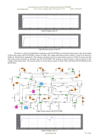
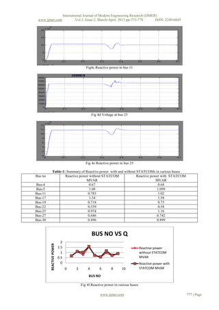
The authors are unaware of any literature dealing STATCOM using Z-Source Inverter based STATCOM for thirty
bus distribution system. This work compares reactive power in thirty bus system at various buses with and without ZSI based
STATCOM.
www.ijmer.com 774 | Page](https://image.slidesharecdn.com/bd32773778-130323020443-phpapp02/85/Bd32773778-2-320.jpg)
![International Journal of Modern Engineering Research (IJMER)
www.ijmer.com Vol.3, Issue.2, March-April. 2013 pp-773-778 ISSN: 2249-6645
V. Conclusion
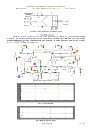
This work has explored the possibility of using Z-Source Inverter based STATCOM system. The thirty bus system
is modeled and simulated using MATLAB software and results are presented. The simulation results of Thirty bus system
with and without STATCOMs are presented. Simulation studies were done using single phase model of balanced three phase
system. It is found that the bus voltages near the STATCOMs are improved and hence the reactive power. Overall power
quality can be improved by using more STATCOMs at the load buses. The simulation results are in line with the predictions.
This system has improved reliability and power quality. The scope for future work is simulation can also be done using
PSCAD or PSIM. The simulation studies can be extended to 64-bus and 128-bus systems. Testing can also be done on
extremely large real time power systems and also the laboratory model for STATCOM can be done using Micro-controller
or DSP processor.
References
[1]. N.G.Hingorani and L.Gyugyi, understanding FACTS, Concepts and technology of Flexible AC Transmission systems, Piscataway,
NJ; IEEE Press, 2000.
[2] S.Nillson, “Special application consideration for custom power systems”, in proc.IEEE power Eng.Soc, winter Meeting 1999, vol.2,
1999, pp.1127-1130.
[3] “R.Mohan and R.K.Varma”, Thyristor based FACTS Controllers for Electrical systems Transmission, Piscataway, NJ; IEEE Press,
2000.
[4] G.F.Reed,M.Takeda,I. Iyoda(1999), “Improved power quality solutions using advanced solid state switching and static
compensation technologies”,IEEE power Engineering Society Winter Meeting, Vol 2,27-31,726-734.
[5] Hannan M.A,Mohamed A.,Hussain A.,Dabbay M.,Power Quality Analysis of STATCOM using Dynamic phasor Modeling,
International journal of Electrical power system Research, 79(2009),993-999.
[6] P.Giroux, G.Sybille, and H. Le-Huy, “Modeling and simulation of a distribution STATCOM using simulink’s power system
blockset”, in proc. Annu. Conf. IEEE Industrial Electronic society, pp, 990-994.
[7] R.Mineski, R.Pawelek, I.Wasiak (2004), “Shunt compensation for power quality improvement using a STATCOM controller,
modeling and simulation”, IEE proc. On Generation, Transmission and Distribution, Vol.151, No.2.
[8] Jianye Chen, Shan song Zanji Wang, “Analysis and implementation of thyristor based STATCOM”, 2006. International conference
on power system Technology.
[9] Nitus vorahonpiput and soranchai chatratana, “STATCOM Analysis and controller design for power system voltage regulation
“Transmission and distribution conference and exhibition 2005: Asia and pacific, IEEE/PES.
[10] M.H.Haque “compensation of Distribution system voltage sag by DVR and DSTATCOM”, Power Tech proceedings 2001, IEEE
Porto Volume: 1, sept.2001.
[11] B.Justus Rabi and Arumugam”, Harmonics study and comparison of Z-Source inverter with Traditional Inverters”, American
journal of applied sciences2 (10):1418-1426, 2005.
[12] F.Z.Peng, M.Shen, F.Z.Peng, and Z.Qian, “Maximum boost control of the Z-source inverter”, in Proc.39th IEEE Industry
Applications conf., vol1, Oct.2004.
[13] M.Shen, J.Wang, A. Joseph, F.Z.Peng, L.M.Tolbert, and D.J.Adams, “Maximum constant boost control of the Z-Source Inverter”,
presented at the IEEE Industry Application soc.Annu.Meeting, 2004.
[14] F.Z.Peng,X.Yuan ,X.Fang and Z.Qian, “Z-Source inverter for adjustable speed drives”,IEEE power Electron .Lett.,vol.1,no.2,pp.33-
35, Jun.2003.
[15] N.Usha and M.Vijaya kumar “Simulation Results of eight-bus system using push-pull inverter based STATCOM” Interntional
journal, JATIT, voL10, No2, Dec’2009.
[16] N.Usha and M.Vijaya kumar “comparison of VSI and ZSI based STATCOM”, Interntional journal, IJERIA, vol3, No1, Feb’2010.
ABOUT THE AUTHORS
N.Usha has obtained her B. Tech degree from S.V.University and M.Tech degree from JNTU, Anantapur.
She has 13 years of teaching experience. She has published three research papers at International level. She is
presently a research scholar at JNTUA, Anantapur, A.P. She is working in the area of STATCOM.
Prof. M.Vijaya Kumar has obtained his B.Tech from S.V.University and M.Tech from NIT, Warangal and
PhD from JNTU, Hyderabad. He has 21years of teaching experience. He has published 45 research papers at
national and International level. His research area is power quality improvement in power systems.
www.ijmer.com 778 | Page](https://image.slidesharecdn.com/bd32773778-130323020443-phpapp02/85/Bd32773778-6-320.jpg)

This document summarizes a research paper about using a Z-Source Inverter (ZSI) based STATCOM to enhance power quality in a thirty bus power system. It first provides background on power quality issues and how Flexible AC Transmission Systems (FACTS) devices like STATCOMs can help address them. It then describes the components and operation of a conventional STATCOM and introduces the ZSI as an alternative inverter topology. The research presented in the paper models and simulates a thirty bus system both with and without a ZSI-based STATCOM to study improvements in voltage regulation and reactive power compensation.