This document provides an overview of the operation and user interface of the BACTEC FX40 System. It describes the following:
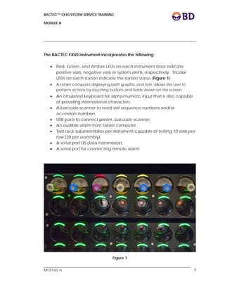
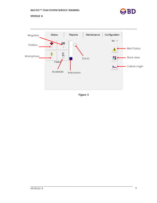
- The user interface includes a touchscreen tablet, barcode scanner, and LED status lights on each station. The tablet allows the user to navigate screens and workflows.
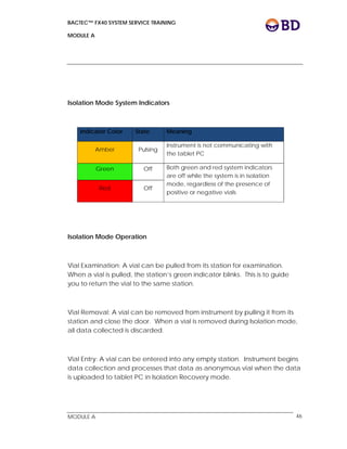
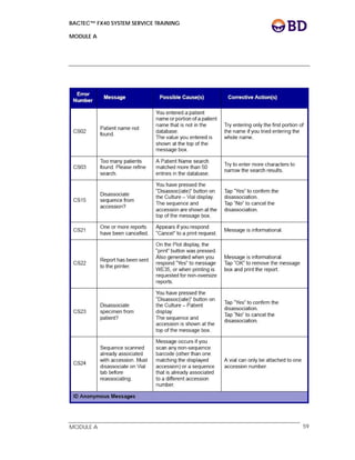
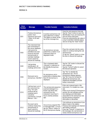
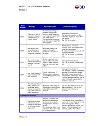
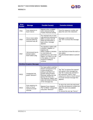
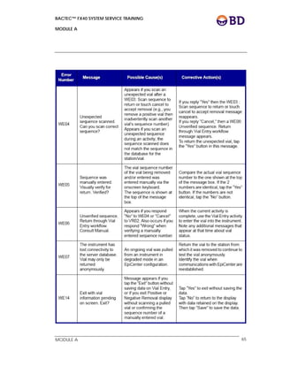
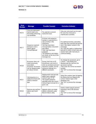
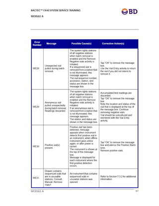
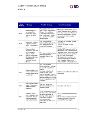
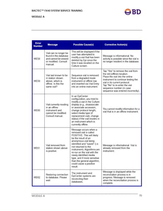
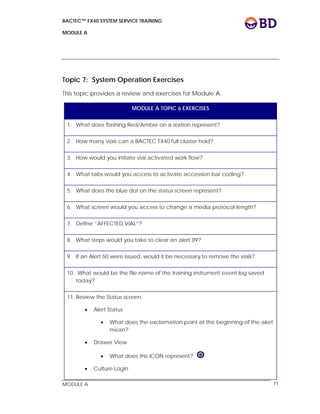
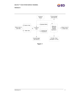
- Key workflows covered include vial entry, positive result removal, and resolving orphaned vials. Vials are placed in stations with illuminated green lights and statuses are tracked via station LED colors and software screens.
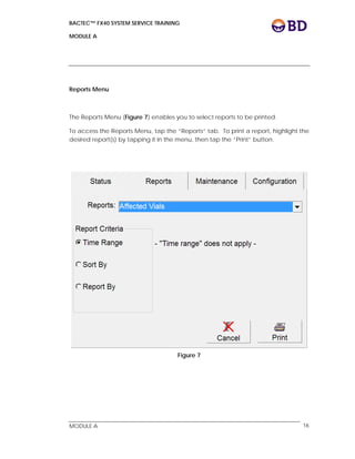
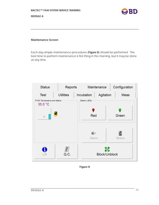
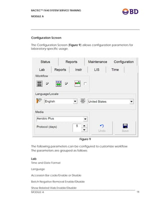
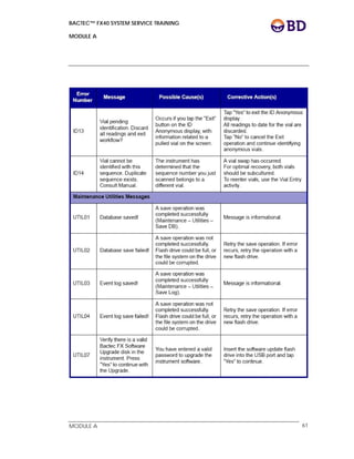
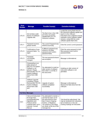
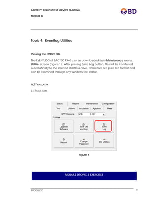
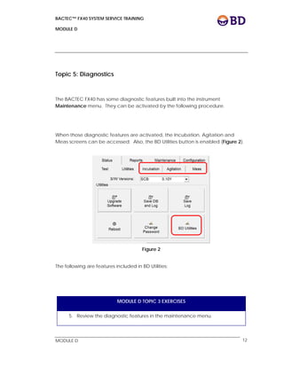
- The system allows for configuration of parameters, maintenance tasks, and generation of reports from test results via the tablet interface. It can integrate with a laboratory information system for sending and receiving patient data.