Download to read offline


![International Research Journal of Engineering and Technology (IRJET) e-ISSN: 2395-0056
Volume: 09 Issue: 06 | June 2022 www.irjet.net p-ISSN: 2395-0072
© 2022, IRJET | Impact Factor value: 7.529 | ISO 9001:2008 Certified Journal | Page 311
FINAL WORKING MODEL
ADVANTAGES
Availability more
We can control the device easily by sending sms and
signals.
More effective.
Cheaper cost and easy to exchange.
High accuracy
When manually operated there are more
chances of errors so automation helps in less
humanerror.
It is reliable as it is automated
DISADVANTAGES
Three Phase supply is not easily available to normal
consumers.
Due to increase in heat motor winding will burned.
FUTURESCOPE
Expansion of this project is we can use current
setting scheme.
When temperature is exceed then motor will burn to
prevent this damage then we can give specific cutoff.
CONCLUSION
In this paper cheaper and simple scheme to start and
control the induction motors using microcontroller is
successfully explained. We can remotely access the motor
using microcontroller. This project has prepared for
controlling , monitoring and theft detection circuit for 3
phase induction motor .This circuit can ON and OFF the
motor through CALL by mobile. LCD display and GSM
module is interfaced with motor so every start , stop
condition of induction motor is displayed on LCD module
as well as call is send to user.
REFERANCES
[1] GSM module for wireless radiation monitoring
system via SMS Nur Aira Abd Rahman,Noor
Hisyam Ibrahim,Lojius Lombigit, Azraf
Azman,Zainudin jaafar Nor Arymaswati Abdullah,
Glam Hadzir Patai Mohamad
[2] Condition Monitoring of 3- ϕ A.C Induction Motor
Using PLC PraveenKumar Shukla, Ankur Namdeo,
Abhishek Dixit
[3] Microcontroller based fault detection and
protection system for induction motor Rupali M
Shivpuje, Mr Swapnil D Patil
[4] Induction Motor Condition Monitoring And
Controlling Based On IOT Seenivasan
V1,Ponkumar K1 ,Venkatraman R1,
Jeslindrusilanesamalar J2
[5] Control and Monitoring of 3 – PhaseInduction
Motor Using PLC Piyush Ahuja, Rajiv Kumar,
Kumar Dhiraj.”](https://image.slidesharecdn.com/irjet-v9i652-221007112743-e3cd5c73/75/MICROCONTROLLER-BASED-ON-INDUCTION-MOTOR-CONDITION-MONITORING-AND-CONTROL-5-2048.jpg)

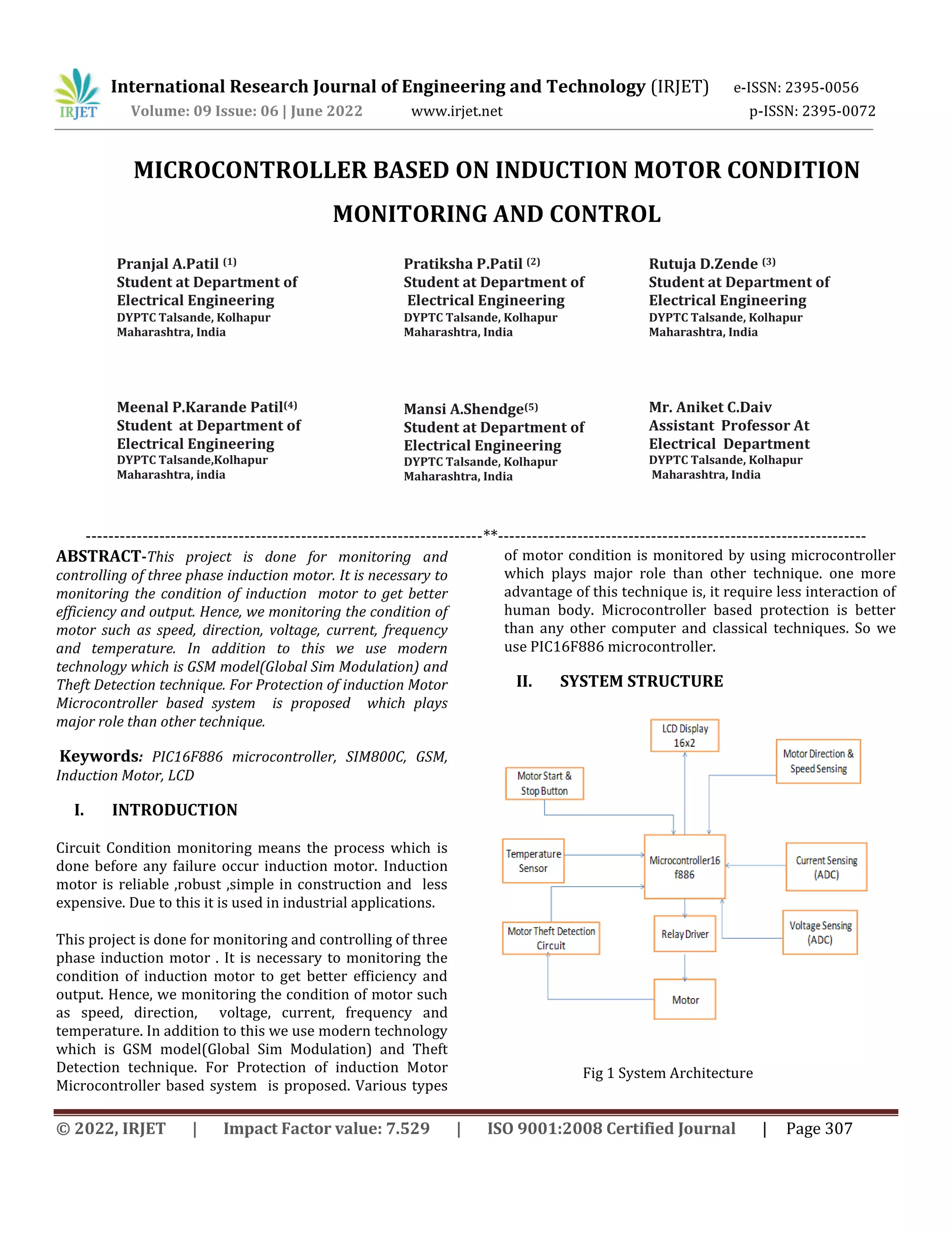
This document describes a microcontroller-based system for monitoring and controlling a three-phase induction motor. The system monitors the motor's speed, direction, voltage, current, frequency, and temperature using sensors connected to a PIC16F886 microcontroller. It also includes GSM and theft detection capabilities. The microcontroller interfaces with various sensors and components like an LCD display, temperature sensor, voltage/current sensors, proximity sensor, relay circuits, and SIM800C GSM module. The system aims to protect the induction motor and provide better efficiency through real-time condition monitoring.


![Share 'speed control_of_dc_motor_using_microcontroller.pptx'[1][1]](https://cdn.slidesharecdn.com/ss_thumbnails/sharespeedcontrolofdcmotorusingmicrocontroller-181012151950-thumbnail.jpg?width=640&height=640&fit=bounds)