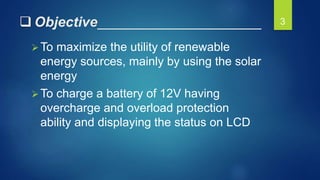
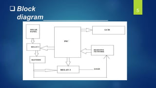
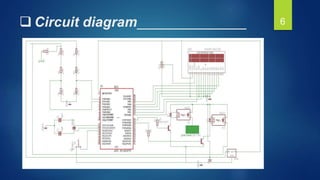
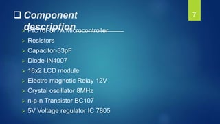
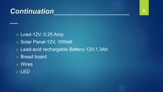
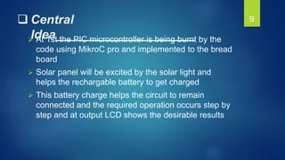
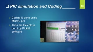
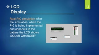
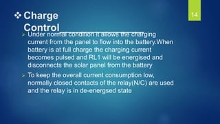
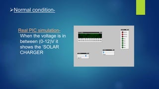
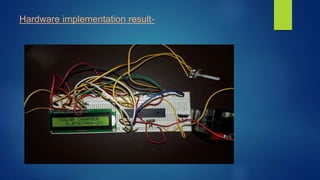
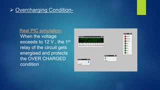
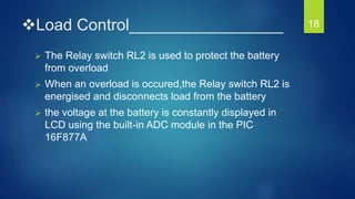
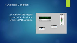
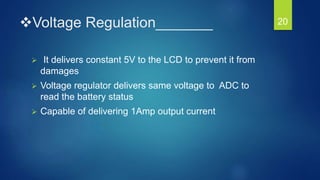
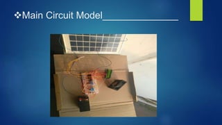
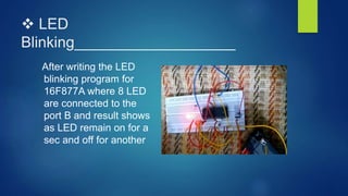
1. Final Year Project Presentation Topic :
MICROCONTROLLER BASED
SOLAR CHARGER
Prepared by-
ECE1, 8th SEM,
ROLL NO. 17,48,50,62
Guide name: Prof. Mukesh Das
Department of Electronics and Communication Engineering
1
2. Outlines___________________
Objective
Introduction
Block diagram
Circuit diagram
Component
description
Central idea
PIC simulation
Hardware
implementation and
Real PIC simulation
LED Blinking
Complete circuit
Future scope
Conclusion
References
2
3. Objective_____________________
To maximize the utility of renewable
energy sources, mainly by using the solar
energy
To charge a battery of 12V having
overcharge and overload protection
ability and displaying the status on LCD
3
4. Introduction__________________
__As the sources of conventional
energy deplete day by day, resorting
to alternative sources of energy like
solar-powered lighting systems are
already available in rural as well as
urban areas. These include solar
lanterns, solar home lighting
systems, solar streetlights, solar
garden lights and solar power
packs. All of them consist of four
components: solar photovoltaic
module, rechargeable battery, solar
charge controller and load.
4
9. Central
Idea____________________ At 1st the PIC microcontroller is being burnt by the
code using MikroC pro and implemented to the bread
board
Solar panel will be excited by the solar light and
helps the rechargable battery to get charged
This battery charge helps the circuit to remain
connected and the required operation occurs step by
step and at output LCD shows the desirable results
9
10. PIC simulation and Coding______
Coding is done using
MikroC pro
Then the Hex file is
burnt by Pickit2
software
10
11. Hardware Implementation______
The objectives of the project is done part by part as the
coding is done separately for -
LCD Display
Charge control
Load control
Voltage regulation
11
14. Charge
Control_______________
Under normal condition it allows the charging
current from the panel to flow into the battery.When
battery is at full charge the charging current
becomes pulsed and RL1 will be energised and
disconnects the solar panel from the battery
To keep the overall current consumption low,
normally closed contacts of the relay(N/C) are used
and the relay is in de-energsed state
14
17. Overcharging Condition-
Real PIC simulation-
When the voltage
exceeds to 12 V , the 1st
relay of the circuit gets
energised and protects
the OVER CHARGED
condition
18. Load Control_________________
The Relay switch RL2 is used to protect the battery
from overload
When an overload is occured,the Relay switch RL2 is
energised and disconnects load from the battery
the voltage at the battery is constantly displayed in
LCD using the built-in ADC module in the PIC
16F877A
18
20. Voltage Regulation_______
It delivers constant 5V to the LCD to prevent it from
damages
Voltage regulator delivers same voltage to ADC to
read the battery status
Capable of delivering 1Amp output current
20
22. LED
Blinking___________________
After writing the LED
blinking program for
16F877A where 8 LED
are connected to the
port B and result shows
as LED remain on for a
sec and off for another
23. Future
scope____________________
By introducing a stepper motor to rotate the
solar panel based on the sun.
By extending the circuit we can give the
electricity which is sufficient to home
requirements.
23
24. Conclusion___________________
__
In this project the parts of the programming are
done by-
LCD pinout setting
LCD initialization and interfacing
Displaying ‘SOLAR CHARGER’
Built-in digital voltmeter logic
Overcharge protection logic
Overload protection logic
24
25. References___________________
_ S.K. Mandal, Microprocessors and Microcontrollers.
Tata McGraw Education Pvt. Ltd., 2010.
E-book: PIC microcontroller text by Muhammad Ali
Mazidi
http://www.electronicsforu.com/
http://www.stackxchange.com/
Manual: MikroC PRO for PIC ver 7.1.0-
Mikroelektronika
http://www.github.com/- lcd library functions for EAGLE
https://download/mikroe.com- Lcd library
25