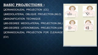
BASICPROJECTIONS OF
MAMMOGRAM
NAME : VENISA PAIS
BATCH : II BMIT
ANATOMY OF BREAST :
The breasts are medically known as the Mammary
Glands.
The mammary glands are made up of lobules , milk
producing glandular structures , and a system of
ducts that transport milk to nipple.
Lymphatic vessels in the breast drain excess fluid.
Both Males and Females have breasts. The male
breast tissue lacks the specialized lobules, as there
is no physiological need for milk production by them.
The breast doesn’t contain muscles. Breast tissue is
located on top of the muscles of chest wall.
 Blood vessels and lymphatic vessels are located
throughout the breast . The lymphatic vessels in the
breast drain to the lymph nodes in the under arm area
(axilla) and behind the breast bone (sternum).
 In females , milk exists the breast at the nipple , which is
surrounded by a darkened area of skin called the
Areola.
 The areola contains small, modified sweat glands known
as Montgomery’s tubercles .
 These glands secrete fluid that serves to lubricate the
nipple during breastfeeding.
BASIC PROJECTIONS :
CRANIOCAUDAL PROJECTION (CC)
MEDIOLATERAL OBLIQUE PROJECTION (MLO)
MAGNIFICATION TECHNIQUE
90-DEGREE MEDIOLATERAL PROJECTION (ML)
90-DEGREE LATEROMEDIAL PROJECTION (LM)
CRANIOCAUDAL PROJECTION FOR CLEAVAGE
(CV)
INDICATIONS :
BREAST CARCINOMA
CALCIFICATION
CYST
EPITHELIAL HYPERPLASIA
FIBROSIS
TUMOR
CRANIOCAUDAL PROJECTION (CC) :
 It has to be done on both the breasts. Only if both
breasts are present.
 Such as Right Craniocaudal(RCC) and Left
Craniocaudal (LCC).
POSITION OF PATIENT :
• Have the patient stand facing the image receptor, or
seat the patient on an adjustable stool facing the unit.
The medial side of the breast to be imaged, elevate
the inframammary fold to its maximal height .
• Adjust the height of the C-arm to the level of the
inferior surface of the patient’s breast.
• Use both hands to pull the breast gently onto the image
receptor holder , while instructing the patient to press
the thorax against the image receptor.
• Keep the breast perpendicular to the chest wall . The
technologist should use his or her fingertips to pull
posterior tissue gently forward to the IR.
• Immobilize the breast with one hand , being careful not
to remove this hand until compression begins.
• Rotate the patients head away from the affected side.
• Inform the patient that compression of breast will be
used and slowly apply compression until the breast feels
taut.
• Instruct the patient to indicate whether the compression becomes
uncomfortable.
• After full compression is achieved and checked, make the Exposure and
release the breast compression immediately.
TECHNICAL FACTORS :
IMAGE RECEPTORS :
8 x 10 inch (18 x 24 cm)
OR 10 x 12 inch (24 x 30 cm )
CENTRAL RAY :
• Perpendicular to the base of the breast.
FACTORS :
kVp :30-40
mAs :200-300
STRUCTURES SHOWN :
The CC projection shows the central , subareolar , and medial fibroglandular
breast tissue . The pectoral muscle is shown in approximately 30% of all CC
images.
EVALUATION CRITERIA :
The following should be clearly shown :
o The PNL extending posteriorly to the edge of the
image and measuring within 1 cm of the depth of
PNL on MLO projection.
o All medial tissue , as shown by the visualization
of medial retroglandular fat and the absence of
fibroglandular tissue extending to the
posteromedial edge of image.
o Nipple in profile ( if possible ) and at mid line,
indicating no exaggeration of positioning.
oFor emphasis of medial tissue, there may be
exclusion of some lateral tissue.
oPectoral muscle seen posterior to medial
retroglandular fat in about 30% of properly
positioned CC images.
oSlight medial skin reflection at the cleavage,
ensuring adequate inclusion of posterior medial
tissue.
oUniform tissue exposure if compression is
adequate.
MEDIOLATERAL OBLIQUE PROJECTION
(MLO) :
 It has to be done on both the breasts . Only if both the
breasts are present.
 Such as Right Mediolateral Oblique (RMLO) and Left
Mediolateral Oblique (LMLO).
POSITION OF PATIENT :
• Have the patient stand facing the IR, or seat the patient
on an adjustable stool facing unit. Rotate the C-arm
between 30 degree to 60 degrees, depending on the
patients body habitus.
• Adjust the height of the C-arm so that the superior
border is level with the axilla.
• Instruct the patient to elevate the arm of the affected
side over the corner of the IR, and to rest the hand on
the adjacent handgrip. The patients elbow should be
flexed and resting posterior to the IR.
• Holding the breast between the thumb and fingers,
gently lift it up, out , and away from the chest wall.
• Center the breast with nipple in profile if possible,
and hold the breast in position.
• Inform the patient that compression will be used and
slowly apply compression until the breast feels taut .
The corner of the compression paddle should be
inferior to the clavicle.
• Instruct the patient to indicate whether the compression becomes
uncomfortable and to hold the opposite breast away from the path of
beam.
• After full compression is achieved , make the Exposure and release the
breast compression immediately.
TECHNICAL FACTORS :
IMAGE RECEPTORS :
8 x 10 inch (18 x 24 cm)
OR 10 x 12 inch (24 x 30 cm)
CENTRAL RAY :
• Perpendicular to the base of the breast.
• The C- arm apparatus is positioned at an angle determined by the slope of the
patients pectoral muscle . (30 degree to 60 degrees).
FACTORS :
kVp :28-40
mAs :150-250
STRUCTURES SHOWN :
The MLO projection usually shows most of the breast tissue , with emphasis on
the lateral aspect and Axilla.
EVALUATION CRITERIA :
The following should be clearly shown :
o PNL measuring within 1 cm of the depth of PNL on CC projection.
o Inferior aspect of the pectoral muscle extending to the PNL or below it if
possible.
o Pectoral muscle showing anterior convexity to ensure relaxed shoulder and
axilla.
o Nipple if possible.
o Open inframammary fold
o Retroglandular fat well visualized to ensure inclusion
of deep fibroglandular breast tissue. Uniform tissue
exposure if compression is adequate.
MAGNIFICATION TECHNIQUE :
This technique is designed to enhance the image of the
area under investigation.
POSITION OF PATIENT :
• Attach the firm , radioluscent magnification platform
designed by the equipment manufacturer to the unit.
The patients breast is positioned on the platform
between the compression device and a nongrid IR.
• Select the smallest focal spot target size (<0.1 mm is
preferred). Most units allow magnification images to
be exposed only using correct focal spot size.
• Select the appropriate compression paddle. Collimate according to the
size of the compression paddle.
• Reposition the patients breast to obtain the projection that best shows the
area of interest.
• When full compression is achieved, make the Exposure and release
breast compression immediately.
TECHNICAL FACTORS :
IMAGE RECEPTORS :
8 x 10 inch ( 18 x 24 cm )
CENTRAL RAY :
• Perpendicular to the area of interest.
FACTORS :
kVp :30-40
mAs :150-250
STRUCTURES SHOWN :
This technique magnifies the area of interest with improved detail, facilitating
determination of the characteristics of microcalcifications and the margins of suspected
lesion.
EVALUATION CRITERIA :
The following should be clearly shown :
o Area of interest within collimated and compressed
margin.
o Improved delineation of number, distribution, and
morphology of microcalcifications.
o Enhanced architectural characteristics of focal
density or mass.
o Uniform tissue exposure if compression is adequate.
90-DEGREE MEDIOLATERAL
PROJECTION (ML) :
POSITION OF PATIENT :
• Have the patient stand facing the IR, or seat the
patient on an adjustable stool facing the unit and
rotate the C-arm assembly 90 degrees, with the x-ray
tube placed on the medial side of the patients breast.
• Have the patient bend slightly forward. Position the
superior corner of the IR high into the axilla, with the
patients elbow flexed and the affected arm resting
behind the IR.
• Pull the breast tissue and pectoral muscle superiorly
and anteriorly, ensuring that the lateral
rib margin is pressed firmly against the edge of the IR.
• Rotate the patient slightly laterally to help bring the medial tissue forward. Gently
pull the medial breast tissue forward from the sternum and position the nipple in
profile.
• Inform the patient that compression of breast will be used. Do not allow the breast
to droop.
• Slowly apply compression until the breast feels taut. Instruct the patient to indicate
whether the compression becomes uncomfortable. Ask the patient to hold the
opposite breast away from the path of beam.
• When full compression is achieved, make the Exposure and release the breast
compression immediately.
TECHNICAL FACTORS :
IMAGE RECEPTOR :
8 x 10 inch (18 x 24 cm )
OR 10 x 12 inch (24 x 30 cm )
CENTRAL RAY :
Perpendicular to the base of the breast.
FACTORS :
kVp :30-40
mAs :150-250
STRUCTURES SHOWN :
This projection shows lesions on the lateral aspect of the breast in the superior or
inferior aspects. It resolves superimposed structures seen on MLO projection.
Localizes a lesion seen on one (or both )of the initial
projections and shows air fluid and flat fluid levels in the
breast structures (i.e ;Milk of calcium, galactoceles) and in
the pnuemocystography.
EVALUATION CRITERIA :
The following should be clearly shown :
o Nipple in profile
o Open inframammary fold
o Retroglandular fat well visualized to ensure inclusion of
deep fibroglandular breast tissue. Uniform tissue
exposure if compression is adequate.
90-DEGREE LATEROMEDIAL
PROJECTION (LM) :
POSITION OF PATIENT :
• Have the patient stand facing the IR, or seat the patient
on an adjustable stool facing unit and rotate the C-arm
90 degrees, with x-ray tube placed on the lateral side of
the patients breast.
• Position the superior corner of the IR at the level of
jugular notch. And have the patient relax the affected
shoulder, flex the elbow, and the rest affected arm over
the top of the IR.
• Pull the breast tissue and pectoral muscle superiorly
and anteriorly, ensuring that the patients sternum is
pressed firmly against the edge of IR.
• Position the nipple in profile. Hold the patients breast up and out. Do not let it
droop.
• Inform the patient that compression of the breast will be used, slowly apply
compression until the patients breast feels taut. Instruct the patient to indicate
whether the compression becomes uncomfortable.
• When full compression is achieved, make the Exposure and release the breast
compression immediately.
TECHNICAL FACTORS :
IMAGE RECEPTOR :
8 x 10 inch ( 18 x 24 cm )
OR 10 x 12 inch ( 24 x 30 cm)
CENRAL RAY :
Perpendicular to the base of the breast.
FACTORS :
kVp : 30-40
mAs :150-250
STRUCTURES SHOWN :
This projection shows lesions on the medial aspect of the breast in the superior
or inferior aspects. It resolves superimposed structures seen on MLO projection,
localizes a lesion seen on one or both of the initial projections.
It shows air-fluid and fat-fluid levels in breast
structures. ( i.e; Milk of calcium, galactoceles ) and in
pneumocystography.
EVALUATION CRITERIA :
The following should be clearly shown :
o Nipple in profile.
o Open inframammary fold.
o Retroglandular fat well visualized to ensure inclusion
of deep fibroglandular breast tissue.
o Uniform tissue exposure if compression is adequate.
CRANIOCAUDAL PROJECTION FOR
CLEAVAGE (CV) :
POSITION OF PATIENT :
• Have the patient stand facing the IR, or seat the
patient on adjustable stool facing the unit and
preselect a manual technique.
• Determine the proper height of the tray by
elevating the inframammary fold to its maximal
height and adjust the height of the C-arm
accordingly.
• Standing behind the patient, use both hands to
lift and pull both breasts gently forward onto the
IR while instructing the patient to press the
thorax against the IR.
• Pull as much medial breast tissue as possible onto the IR, and rotate the patients
head away from the affected side.
• Inform the patient that compression of the breast will be used, slowly apply
compression until the breast feels taut.
• A quadrant compression paddle is used because it allows better compression of
the cleavage area and allows more of the area of interest to be pulled into the
imaging area.
• Instruct the patient to indicate when the compression becomes uncomfortable.
• When full compression is achieved, make the Exposure and release breast
compression immediately.
TECHNICAL FACTORS :
IMAGE RECEPTOR :
8 x 10 inch ( 18 x 24 cm )
OR 10 x 12 inch ( 24 x 30 cm )
CENTRAL RAY :
Perpendicular to either the area of interest or the centered cleavage.
FACTORS :
kVp :30-40
mAs :150-300
STRUCURES SHOWN :
This projection shows lesions located in the deep posteromedial aspect of the breast.
EVALUATION CRITERIA :
The following should be clearly shown :
o Area of interest over the central portion of the IR
with cleavage slightly off-centered or with cleavage
centered to the IR and manual technique selected.
o Deep medial tissue of affected breast.
o All medial tissue included, as shown by the
visualization of medial retroglandular fat and
absence of any fibroglandular tissue extending to
posteromedial edge of imaged breasts.
o Uniform tissue exposure if compression is adequate.
REFERENCE :
MERRIL’S ATLAS OF RADIOGRAPHIC
POSITIONING AND PROCEDURES.
NEXT TOPIC :
BASIC PROJECTIONS OF LEG -
ADIL

Basic projections of mammogram

  • 1.
    BASICPROJECTIONS OF MAMMOGRAM NAME :VENISA PAIS BATCH : II BMIT
  • 2.
    ANATOMY OF BREAST: The breasts are medically known as the Mammary Glands. The mammary glands are made up of lobules , milk producing glandular structures , and a system of ducts that transport milk to nipple. Lymphatic vessels in the breast drain excess fluid. Both Males and Females have breasts. The male breast tissue lacks the specialized lobules, as there is no physiological need for milk production by them. The breast doesn’t contain muscles. Breast tissue is located on top of the muscles of chest wall.
  • 3.
     Blood vesselsand lymphatic vessels are located throughout the breast . The lymphatic vessels in the breast drain to the lymph nodes in the under arm area (axilla) and behind the breast bone (sternum).  In females , milk exists the breast at the nipple , which is surrounded by a darkened area of skin called the Areola.  The areola contains small, modified sweat glands known as Montgomery’s tubercles .  These glands secrete fluid that serves to lubricate the nipple during breastfeeding.
  • 4.
    BASIC PROJECTIONS : CRANIOCAUDALPROJECTION (CC) MEDIOLATERAL OBLIQUE PROJECTION (MLO) MAGNIFICATION TECHNIQUE 90-DEGREE MEDIOLATERAL PROJECTION (ML) 90-DEGREE LATEROMEDIAL PROJECTION (LM) CRANIOCAUDAL PROJECTION FOR CLEAVAGE (CV)
  • 6.
  • 7.
    CRANIOCAUDAL PROJECTION (CC):  It has to be done on both the breasts. Only if both breasts are present.  Such as Right Craniocaudal(RCC) and Left Craniocaudal (LCC). POSITION OF PATIENT : • Have the patient stand facing the image receptor, or seat the patient on an adjustable stool facing the unit. The medial side of the breast to be imaged, elevate the inframammary fold to its maximal height . • Adjust the height of the C-arm to the level of the inferior surface of the patient’s breast.
  • 8.
    • Use bothhands to pull the breast gently onto the image receptor holder , while instructing the patient to press the thorax against the image receptor. • Keep the breast perpendicular to the chest wall . The technologist should use his or her fingertips to pull posterior tissue gently forward to the IR. • Immobilize the breast with one hand , being careful not to remove this hand until compression begins. • Rotate the patients head away from the affected side. • Inform the patient that compression of breast will be used and slowly apply compression until the breast feels taut.
  • 9.
    • Instruct thepatient to indicate whether the compression becomes uncomfortable. • After full compression is achieved and checked, make the Exposure and release the breast compression immediately.
  • 10.
    TECHNICAL FACTORS : IMAGERECEPTORS : 8 x 10 inch (18 x 24 cm) OR 10 x 12 inch (24 x 30 cm ) CENTRAL RAY : • Perpendicular to the base of the breast. FACTORS : kVp :30-40 mAs :200-300 STRUCTURES SHOWN : The CC projection shows the central , subareolar , and medial fibroglandular breast tissue . The pectoral muscle is shown in approximately 30% of all CC images.
  • 11.
    EVALUATION CRITERIA : Thefollowing should be clearly shown : o The PNL extending posteriorly to the edge of the image and measuring within 1 cm of the depth of PNL on MLO projection. o All medial tissue , as shown by the visualization of medial retroglandular fat and the absence of fibroglandular tissue extending to the posteromedial edge of image. o Nipple in profile ( if possible ) and at mid line, indicating no exaggeration of positioning.
  • 12.
    oFor emphasis ofmedial tissue, there may be exclusion of some lateral tissue. oPectoral muscle seen posterior to medial retroglandular fat in about 30% of properly positioned CC images. oSlight medial skin reflection at the cleavage, ensuring adequate inclusion of posterior medial tissue. oUniform tissue exposure if compression is adequate.
  • 13.
    MEDIOLATERAL OBLIQUE PROJECTION (MLO):  It has to be done on both the breasts . Only if both the breasts are present.  Such as Right Mediolateral Oblique (RMLO) and Left Mediolateral Oblique (LMLO). POSITION OF PATIENT : • Have the patient stand facing the IR, or seat the patient on an adjustable stool facing unit. Rotate the C-arm between 30 degree to 60 degrees, depending on the patients body habitus. • Adjust the height of the C-arm so that the superior border is level with the axilla.
  • 14.
    • Instruct thepatient to elevate the arm of the affected side over the corner of the IR, and to rest the hand on the adjacent handgrip. The patients elbow should be flexed and resting posterior to the IR. • Holding the breast between the thumb and fingers, gently lift it up, out , and away from the chest wall. • Center the breast with nipple in profile if possible, and hold the breast in position. • Inform the patient that compression will be used and slowly apply compression until the breast feels taut . The corner of the compression paddle should be inferior to the clavicle.
  • 15.
    • Instruct thepatient to indicate whether the compression becomes uncomfortable and to hold the opposite breast away from the path of beam. • After full compression is achieved , make the Exposure and release the breast compression immediately.
  • 16.
    TECHNICAL FACTORS : IMAGERECEPTORS : 8 x 10 inch (18 x 24 cm) OR 10 x 12 inch (24 x 30 cm) CENTRAL RAY : • Perpendicular to the base of the breast. • The C- arm apparatus is positioned at an angle determined by the slope of the patients pectoral muscle . (30 degree to 60 degrees). FACTORS : kVp :28-40 mAs :150-250
  • 17.
    STRUCTURES SHOWN : TheMLO projection usually shows most of the breast tissue , with emphasis on the lateral aspect and Axilla. EVALUATION CRITERIA : The following should be clearly shown : o PNL measuring within 1 cm of the depth of PNL on CC projection. o Inferior aspect of the pectoral muscle extending to the PNL or below it if possible. o Pectoral muscle showing anterior convexity to ensure relaxed shoulder and axilla.
  • 18.
    o Nipple ifpossible. o Open inframammary fold o Retroglandular fat well visualized to ensure inclusion of deep fibroglandular breast tissue. Uniform tissue exposure if compression is adequate.
  • 19.
    MAGNIFICATION TECHNIQUE : Thistechnique is designed to enhance the image of the area under investigation. POSITION OF PATIENT : • Attach the firm , radioluscent magnification platform designed by the equipment manufacturer to the unit. The patients breast is positioned on the platform between the compression device and a nongrid IR. • Select the smallest focal spot target size (<0.1 mm is preferred). Most units allow magnification images to be exposed only using correct focal spot size.
  • 20.
    • Select theappropriate compression paddle. Collimate according to the size of the compression paddle. • Reposition the patients breast to obtain the projection that best shows the area of interest. • When full compression is achieved, make the Exposure and release breast compression immediately.
  • 21.
    TECHNICAL FACTORS : IMAGERECEPTORS : 8 x 10 inch ( 18 x 24 cm ) CENTRAL RAY : • Perpendicular to the area of interest. FACTORS : kVp :30-40 mAs :150-250 STRUCTURES SHOWN : This technique magnifies the area of interest with improved detail, facilitating determination of the characteristics of microcalcifications and the margins of suspected lesion.
  • 22.
    EVALUATION CRITERIA : Thefollowing should be clearly shown : o Area of interest within collimated and compressed margin. o Improved delineation of number, distribution, and morphology of microcalcifications. o Enhanced architectural characteristics of focal density or mass. o Uniform tissue exposure if compression is adequate.
  • 23.
    90-DEGREE MEDIOLATERAL PROJECTION (ML): POSITION OF PATIENT : • Have the patient stand facing the IR, or seat the patient on an adjustable stool facing the unit and rotate the C-arm assembly 90 degrees, with the x-ray tube placed on the medial side of the patients breast. • Have the patient bend slightly forward. Position the superior corner of the IR high into the axilla, with the patients elbow flexed and the affected arm resting behind the IR. • Pull the breast tissue and pectoral muscle superiorly and anteriorly, ensuring that the lateral
  • 24.
    rib margin ispressed firmly against the edge of the IR. • Rotate the patient slightly laterally to help bring the medial tissue forward. Gently pull the medial breast tissue forward from the sternum and position the nipple in profile. • Inform the patient that compression of breast will be used. Do not allow the breast to droop. • Slowly apply compression until the breast feels taut. Instruct the patient to indicate whether the compression becomes uncomfortable. Ask the patient to hold the opposite breast away from the path of beam. • When full compression is achieved, make the Exposure and release the breast compression immediately.
  • 25.
    TECHNICAL FACTORS : IMAGERECEPTOR : 8 x 10 inch (18 x 24 cm ) OR 10 x 12 inch (24 x 30 cm ) CENTRAL RAY : Perpendicular to the base of the breast. FACTORS : kVp :30-40 mAs :150-250 STRUCTURES SHOWN : This projection shows lesions on the lateral aspect of the breast in the superior or inferior aspects. It resolves superimposed structures seen on MLO projection.
  • 26.
    Localizes a lesionseen on one (or both )of the initial projections and shows air fluid and flat fluid levels in the breast structures (i.e ;Milk of calcium, galactoceles) and in the pnuemocystography. EVALUATION CRITERIA : The following should be clearly shown : o Nipple in profile o Open inframammary fold o Retroglandular fat well visualized to ensure inclusion of deep fibroglandular breast tissue. Uniform tissue exposure if compression is adequate.
  • 27.
    90-DEGREE LATEROMEDIAL PROJECTION (LM): POSITION OF PATIENT : • Have the patient stand facing the IR, or seat the patient on an adjustable stool facing unit and rotate the C-arm 90 degrees, with x-ray tube placed on the lateral side of the patients breast. • Position the superior corner of the IR at the level of jugular notch. And have the patient relax the affected shoulder, flex the elbow, and the rest affected arm over the top of the IR. • Pull the breast tissue and pectoral muscle superiorly and anteriorly, ensuring that the patients sternum is pressed firmly against the edge of IR.
  • 28.
    • Position thenipple in profile. Hold the patients breast up and out. Do not let it droop. • Inform the patient that compression of the breast will be used, slowly apply compression until the patients breast feels taut. Instruct the patient to indicate whether the compression becomes uncomfortable. • When full compression is achieved, make the Exposure and release the breast compression immediately.
  • 29.
    TECHNICAL FACTORS : IMAGERECEPTOR : 8 x 10 inch ( 18 x 24 cm ) OR 10 x 12 inch ( 24 x 30 cm) CENRAL RAY : Perpendicular to the base of the breast. FACTORS : kVp : 30-40 mAs :150-250 STRUCTURES SHOWN : This projection shows lesions on the medial aspect of the breast in the superior or inferior aspects. It resolves superimposed structures seen on MLO projection, localizes a lesion seen on one or both of the initial projections.
  • 30.
    It shows air-fluidand fat-fluid levels in breast structures. ( i.e; Milk of calcium, galactoceles ) and in pneumocystography. EVALUATION CRITERIA : The following should be clearly shown : o Nipple in profile. o Open inframammary fold. o Retroglandular fat well visualized to ensure inclusion of deep fibroglandular breast tissue. o Uniform tissue exposure if compression is adequate.
  • 31.
    CRANIOCAUDAL PROJECTION FOR CLEAVAGE(CV) : POSITION OF PATIENT : • Have the patient stand facing the IR, or seat the patient on adjustable stool facing the unit and preselect a manual technique. • Determine the proper height of the tray by elevating the inframammary fold to its maximal height and adjust the height of the C-arm accordingly. • Standing behind the patient, use both hands to lift and pull both breasts gently forward onto the IR while instructing the patient to press the thorax against the IR.
  • 32.
    • Pull asmuch medial breast tissue as possible onto the IR, and rotate the patients head away from the affected side. • Inform the patient that compression of the breast will be used, slowly apply compression until the breast feels taut. • A quadrant compression paddle is used because it allows better compression of the cleavage area and allows more of the area of interest to be pulled into the imaging area. • Instruct the patient to indicate when the compression becomes uncomfortable. • When full compression is achieved, make the Exposure and release breast compression immediately.
  • 33.
    TECHNICAL FACTORS : IMAGERECEPTOR : 8 x 10 inch ( 18 x 24 cm ) OR 10 x 12 inch ( 24 x 30 cm ) CENTRAL RAY : Perpendicular to either the area of interest or the centered cleavage. FACTORS : kVp :30-40 mAs :150-300 STRUCURES SHOWN : This projection shows lesions located in the deep posteromedial aspect of the breast.
  • 34.
    EVALUATION CRITERIA : Thefollowing should be clearly shown : o Area of interest over the central portion of the IR with cleavage slightly off-centered or with cleavage centered to the IR and manual technique selected. o Deep medial tissue of affected breast. o All medial tissue included, as shown by the visualization of medial retroglandular fat and absence of any fibroglandular tissue extending to posteromedial edge of imaged breasts. o Uniform tissue exposure if compression is adequate.
  • 35.
    REFERENCE : MERRIL’S ATLASOF RADIOGRAPHIC POSITIONING AND PROCEDURES.
  • 36.
    NEXT TOPIC : BASICPROJECTIONS OF LEG - ADIL