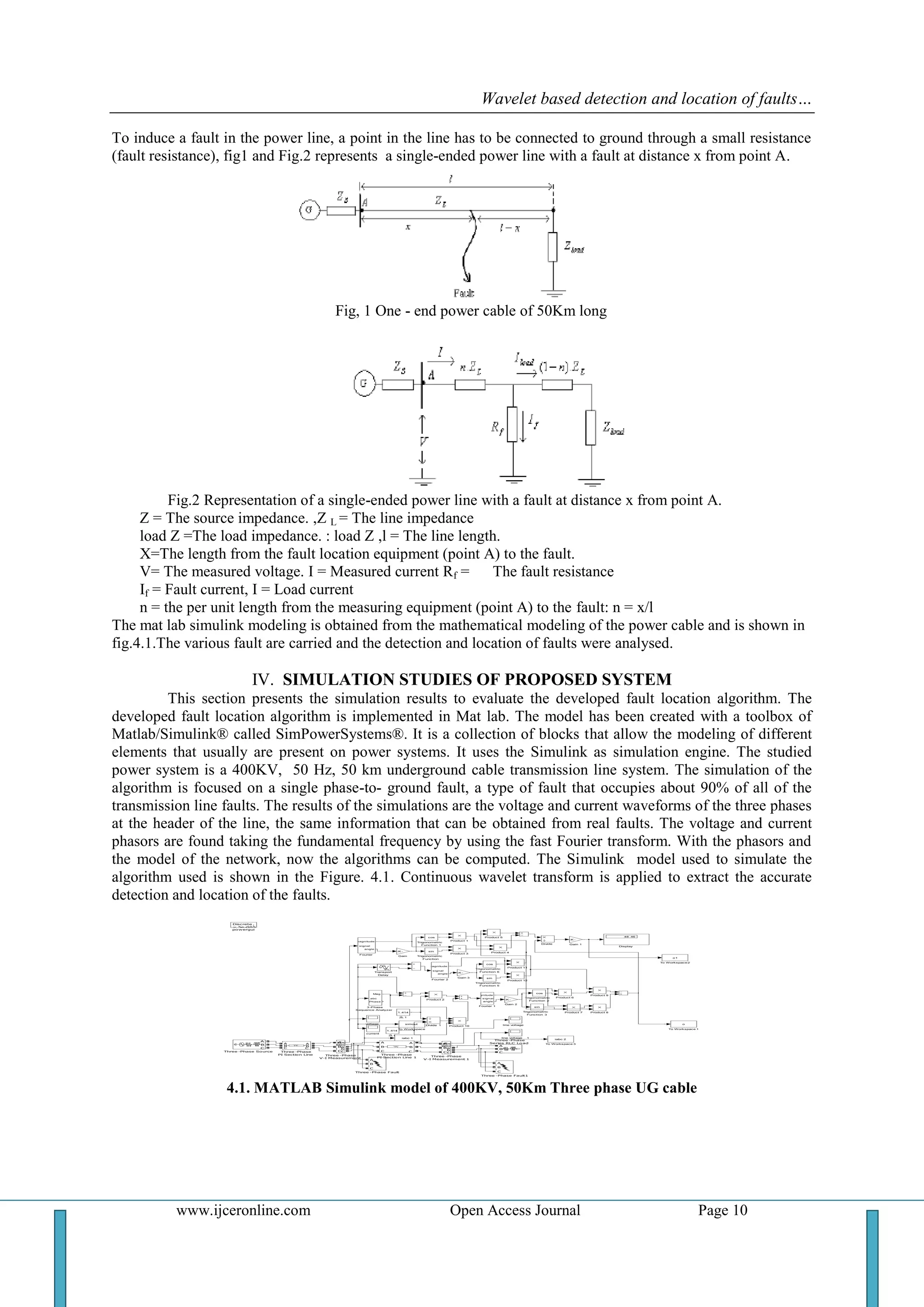
This document presents a method for detecting and locating faults in underground power cables using wavelet transforms. A 400kV, 50km underground cable system is modeled in MATLAB Simulink. Various single-phase, two-phase, and three-phase faults are simulated at distances of 25km and 50km from the measurement point. Voltage and current signals are analyzed using continuous wavelet transforms to detect and locate faults. Simulation results show the method can accurately estimate fault locations, with errors generally under 7%. The method is capable of determining fault type and location for both transmission and distribution cables.
![ISSN (e): 2250 – 3005 || Vol, 05 || Issue,02 || February – 2015 ||
International Journal of Computational Engineering Research (IJCER)
www.ijceronline.com Open Access Journal Page 8
Wavelet based detection and location of faults in 400kv, 50km
Underground Power Cables
D.Prabhavathi1
, K.Prakasam2
, Dr.M.Suryakalavathi3
,
Dr.B.Ravindranath Reddy4
1
Department of Electrical and Electronics Engineering, Sri Sivani College of
Engineering,Srikakulam,A.P.INDIA
2
Department of Electrical and Electronics Engineering, Sri Sivani College of
Engineering,Srikakulam,A.P,INDIA
3
Department of Electrical and Electronics Engineering, JNTUH, Hyderabad, INDIA.
4
Department of Electrical and Electronics Engineering, JNTUH, Hyderabad, INDIA.
I. INTRODUCTION
Detection and Location of faults in power transmission lines is one of the main concerns for all the
electric utilities as the accurate detection and fault location can help to restore the power supply in the shortest
possible time. Fault location methods for transmission lines are broadly classified as impedance based method
which uses the steady state fundamental components of voltage and current values [1–3], travelling wave (TW)
based method which uses incident and reflected TWs observed at the measuring end(s) of the line [4, 5], and
knowledge based method which uses artificial neural network and/or pattern recognition techniques [6,7]. All
the above methods use the measured data either from one end of the transmission line or from all ends. Fault
analysis methods are an important tool used by protection engineers to estimate power system currents and
voltages during disturbances. It provides information for protection system setting, coordination and efficiency
analysis studies. Today, three approaches are used in the industry for such analysis: classical symmetrical
components, phase variable approach and complete time-domain simulations [19]. Classical fault analysis of
unbalanced power systems is based on symmetrical components approach [20, 21]. However, in un transposed
feeders with single-phase or double- phase laterals, the symmetrical component methods do not consider
accurately these specific characteristics [22]. Hence, symmetrical components based techniques may not provide
accurate results for power distribution systems, which are normally characterized by those asymmetries. With
industrial computer facilities improvement, the fault analysis phase variable approach has been proposed to
substitute the symmetrical components methods on distribution systems [23]. In the phase variable approach,
system voltages and currents are related through impedance and admittance matrices based on phase frame
representation, considering the typical distribution systems asymmetries. However, fault analysis is still fault
resistance dependant [24]. Due to fault resistance stochastic nature, typical fault analysis studies consider the
fault paths as an ideal short-circuit. To overcome this limitation, recent studies suggest the usage of fault
resistance estimation algorithms [25–27]. These works provide a fault resistance estimate using symmetrical
components or modal analysis techniques, restricting the application on balanced systems with equally
transposed lines. The usage of artificial intelligence has also been recently proposed in order to overcome the
fault resistance effects in classical power system protection [28] and fault location [29] applications.
ABSTRACT
In this paper, a method for detection and location of fault in a power line is presented.
This method can be applied for both transmission and distribution power lines of underground
cables. The proposed method is capable to determine type of fault the fault location upon its
occurrence, based on the data available from the measuring equipment. The algorithm
presented uses the fault steady-state data (voltages and currents) and the system parameters, to
calculate the fault location. The influence of the fault resistance that depends on the design
characteristics of the power line is disregarded. The proposed method has been modeled in mat
lab simulink of version 7.8.
KEYWORDS: Cables, distribution, Fault location, Fault diagnosis, steady state, transmission,
underground, wavelet,](https://image.slidesharecdn.com/b05208015-150309004336-conversion-gate01/75/Wavelet-based-detection-and-location-of-faults-in-400kv-50km-Underground-Power-Cables-1-2048.jpg)
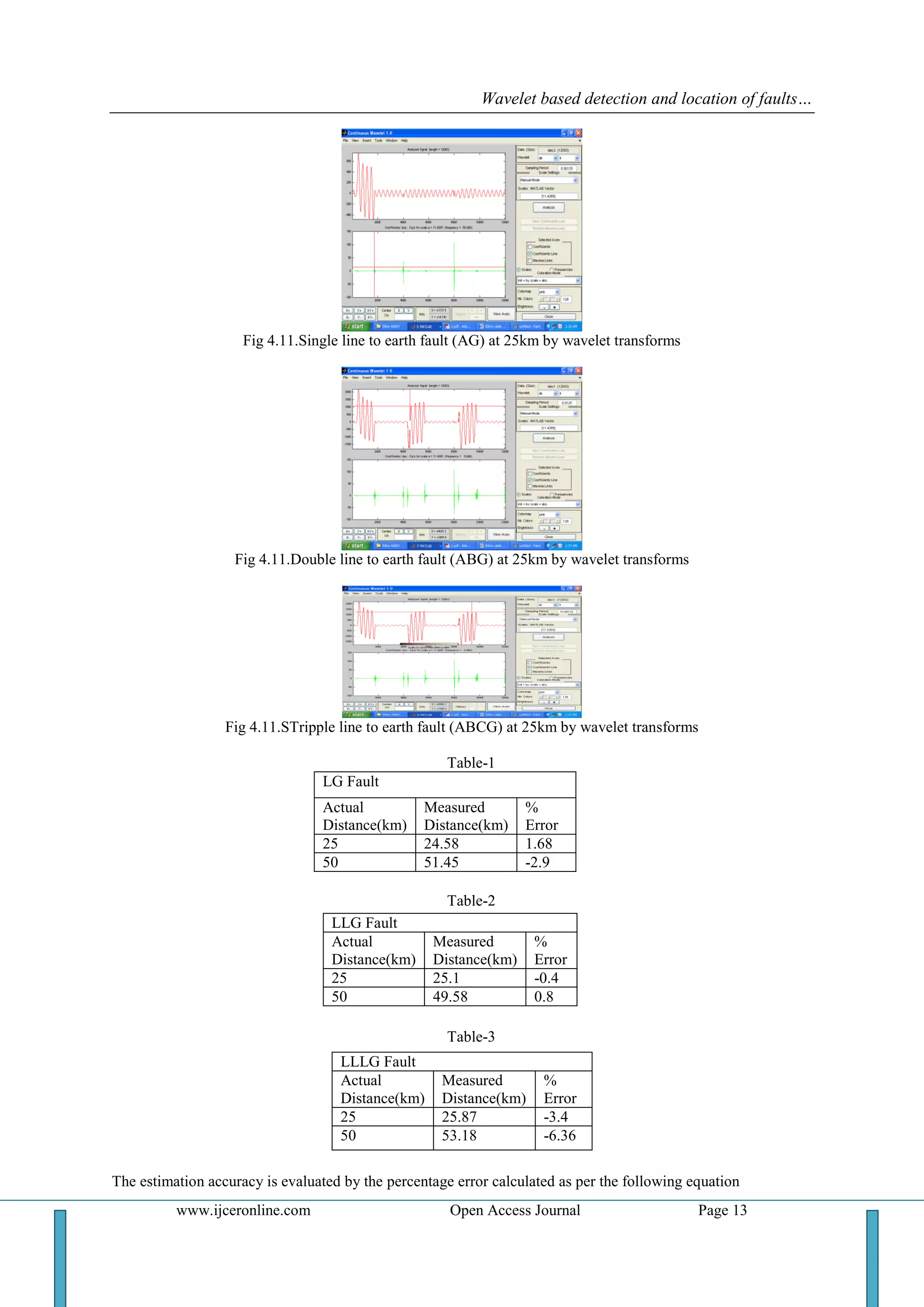
![Wavelet based detection and location of faults…
www.ijceronline.com Open Access Journal Page 14
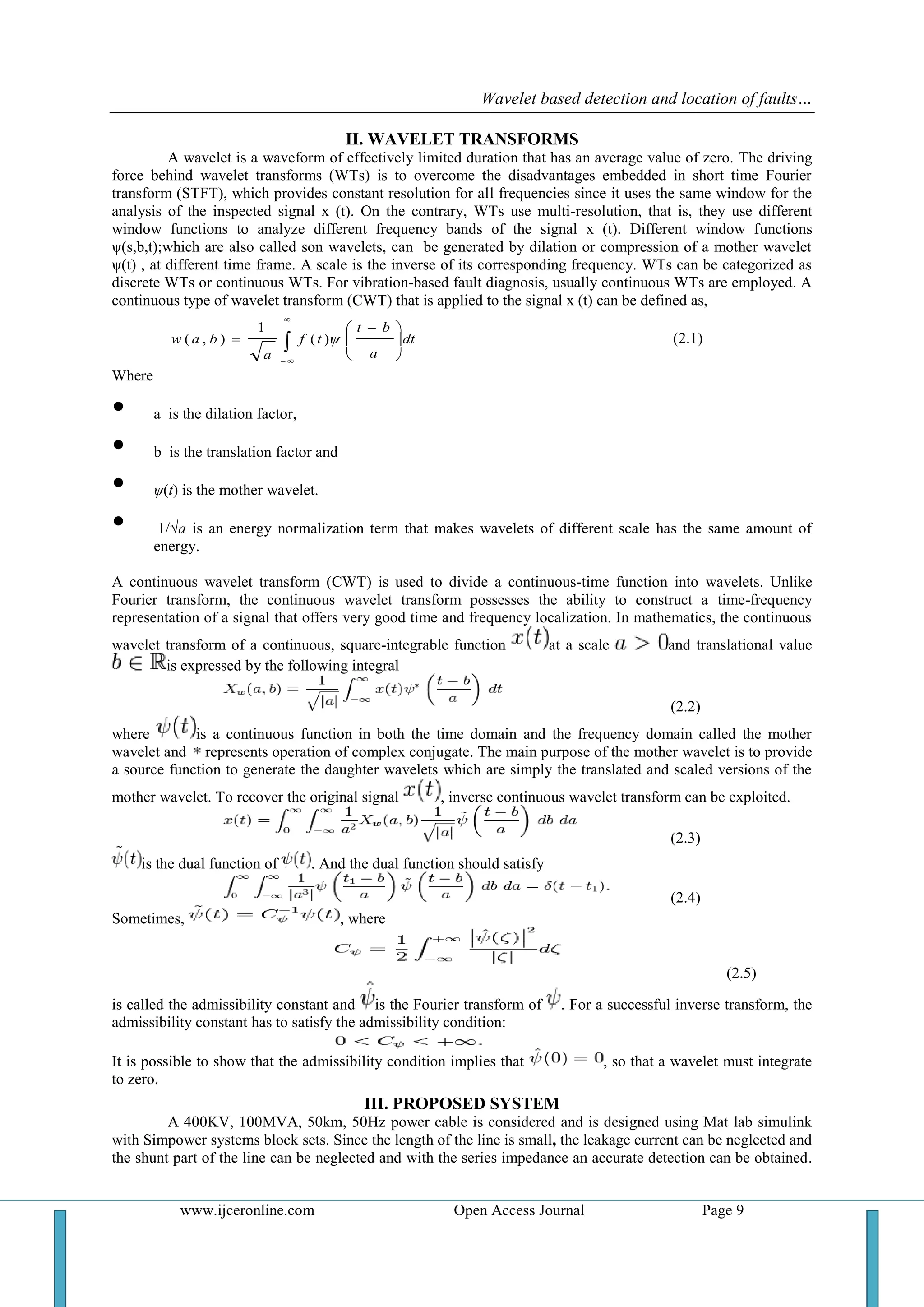
Where the location of the fault is defined as the distance between the bus at which the measuring equipment are
installed, and the fault point. As can be seen, the fault location estimates are satisfactory. The location fault is
estimated in wavelet transform between the two peaks of the waveform.
V. CONCLUSIONS
This paper presents detection and location of fault in 400KV underground .The proposed algorithm
uses the steady-state data (voltages and currents), available by the measuring equipment, to calculate the fault
location. The influence of the fault resistance is disregarded. The proposed method can be used to built a stand-
alone fault locating equipment and as a part of a protective device as an impedance relay. Simulation studies
have shown that the proposed algorithm can yield quite accurate estimates of the fault detection and location.
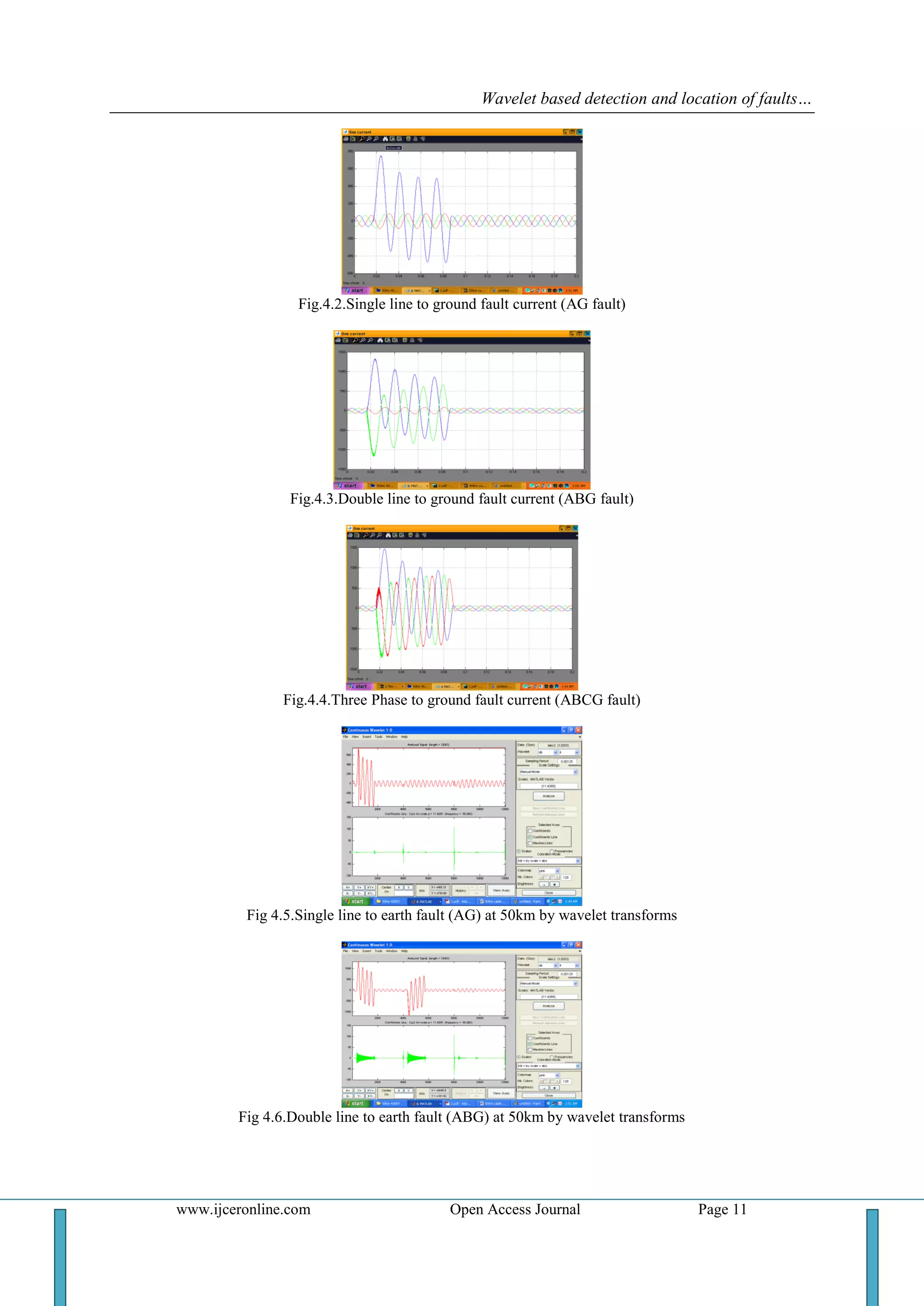
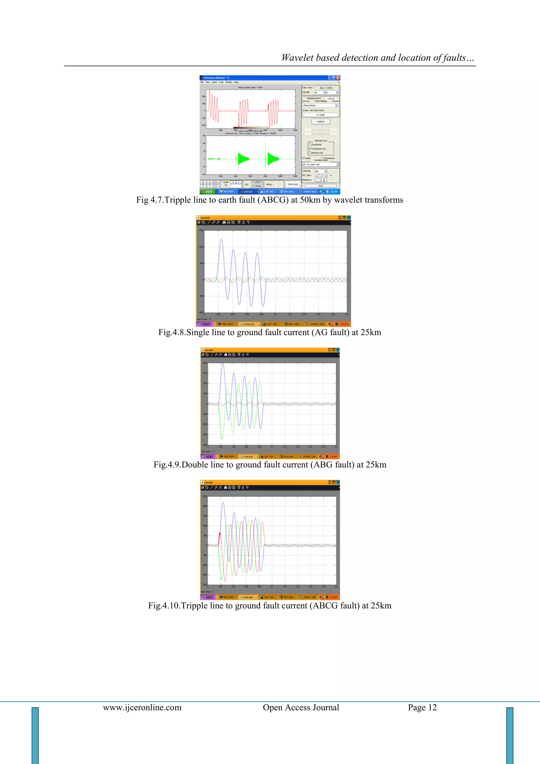
The resultant of all types of faults are shown in figures 4.2 to 4.7 for fault at 50km and from figures 4.8 to 4.11
for faults at 25km.The resultant values of all faults are tabulated in table I, table II and table III. From this it can
be observed that the wavelet transform gives better results in detection and location of faults. The maximum
error in this analysis is -6.36%
REFERENCES
[1] Filomena AD, Resener M, Salim RH, Bretas AS. Extended impedance-based fault location formulation for unbalanced
underground distribution systems. In: IEEE PESGM-conversion & delivery of electrical energy in the 21st century; 2008 July. p.
1– 8.
[2] Amir AA, Ramar K. Accurate one-end fault location for overhead transmission lines in interconnected power systems. Int J
Electr Power Energy Syst 2010;32(5):383–9.
[3] Abdel-Fattah M, Lehtonen M. A new transient impedance-based algorithm for earth fault detection in medium voltage network
[4] Bo ZQ, Johns AT, Aggarwal, AK. A novel fault locator based on the detection of fault generated high frequency transients. In:
Proceedings of 6th IEE developments in power systems protection conference; March 1997. p. 197– 200. [5] Evrenosoglu CY,
Abur A. Travelling wave based fault location for teed circuits. IEEE Trans Power Deliv 2005;20(2):1115–21.
[6] Anamika Jain, Kale VS, Thoke AS. Application of artificial neural networks to transmission line faulty phase selection and fault
distance location. In: IASTED, Chiang Mai, Thailand; 29–31 March 2006. p. 262–7.
[7] Fernandez RMC, Rojas HND. An overview of wavelet transforms applications in power systems. In: 14th PSCC, Sevilla, Spain;
2002. p. 1–8.
[8] Lee H. Development of accurate traveling wave fault locator using global positioning satellites. In: 20th Annual western
protective relay conference, Spokane Washington, USA; October 1993. p. 197–204.
[9] Jiang F, Bo ZQ, Weller G, Chin SM, Redfern MA. A GPS based fault location scheme for distribution line using wavelet
transform technique. In: international conference on power system transients, Budapest, Hungary, June 1999. p. 224–8.
[10] Elhaffar A, Lehtonen M. An improved GPS current traveling-wave fault locator in EHV transmission networks using few
recordings. In: Proceedings of international conference on future power systems, Schiphol–Amsterdam, Netherlands; 1–5
November 2005.
[11] Silva MD, Oleskovicz M, Coury DV. Hybrid fault locator for three-terminal lines based on wavelet transforms. Electr Power
Syst Res 2008;78(11):1980–8.
[12] Lin YH, Liu CW, Yu CS. A new fault locator for three-terminal transmission lines—using two-terminal synchronized voltage,
current phasors. IEEE Trans Power Deliv 2002;17(2):452–9.
[13] Chen CS, Liu CW, Fast and accurate fault detection/location algorithms for double-circuit/three-terminal lines using phasor
measurement units. J Chin Inst Eng 2003;26(3):289–99.
[14] Ngu EE, Ramar K. Single-ended traveling wave based fault location on two terminal transmission lines. In: IEEE TENCON,
Singapore; 23rd–26th November, 2009. p. 1–4. ISBN: 978-1-4244-4547-9.
[15] Zheng XY, Li XM, Ding JY, Duan ZY. Study on impedance-traveling wave assembled algorithm in one-terminal fault location
system for transmission lines. In: 3rd International conference on electric utility deregulation & restructuring and power
technologies; April 2008. p. 1123–6.
[16] Yerekar SR. Fault location system for transmission lines in one-terminal by using impedance-traveling wave assemble.
<http://eeeic.eu/proc/ technical_program_cd.html> [accessed August 2009].
[17] Dong XZ, Chen Z, He XZ, Wang KH, Luo CM. Optimizing solution of fault location. IEEE Power Eng Soc Summer Meet
2002;3:1113–7.
[18] Rajendra S, McLaren PG. Traveling wave techniques applied to the protection of teed circuits: multi-phase/multi-circuit system.
IEEE Trans Power Apparat Syst 1985 Dec;104:3351–7.
[19] Halpin SM, Grigsby LL. A comparison of fault calculation procedures for industrial power distribution systems: the past, the
present and the future. In: Proceedings of the IEEE international conference on industrial technology; 1994.
[20] Halpin SM, Grigsby LL, Gross CA, Nelms RM. An improved fault analysis algorithm for unbalanced multi-phase power
distribution systems. IEEE Trans Power Deliv 1994;9(3):1332–8.
[21] Anderson PM. Analysis of faulted power systems. New York (USA): IEEE; 1995.
Acknowledgements
The authors wish to gratefully acknowledge Smt.Dr.M.Suryakalavathi, Prof Dept of E.E.E, J.N.T.U.H,
Hyderabad and her support for the completion of this work. The authors also wish to gratefully acknowledge
Dr.B.Ravindranath Reddy, Deputy Executive Engineer, J.N.T.U.H, and Hyderabad for the support given in the
completion of this research work.](https://image.slidesharecdn.com/b05208015-150309004336-conversion-gate01/75/Wavelet-based-detection-and-location-of-faults-in-400kv-50km-Underground-Power-Cables-7-2048.jpg)


![ANPARA THERMAL POWER STATION[1] sangam.pdf](https://cdn.slidesharecdn.com/ss_thumbnails/anparathermalpowerstation1sangam-251121115219-9261cde4-thumbnail.jpg?width=640&height=640&fit=bounds)


