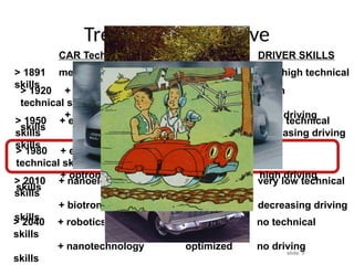
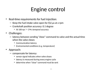
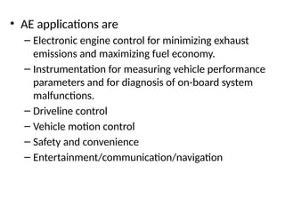
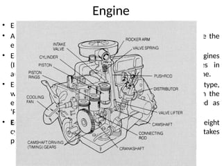
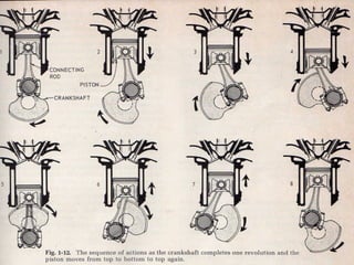
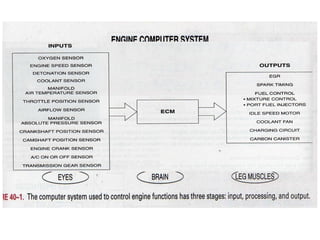
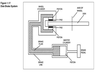
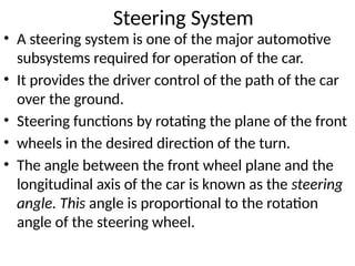
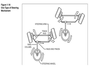
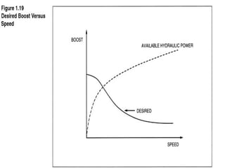
Automotive Electronics
Dr. Shashidhara H R
Course Outcomes:On successful completion of the course, the
students will be able to:
1.Explain in a concise manner how the general automotive
electronics useful in the design and development of vehicles.
2.Understand constraints and opportunities of sensors and
actuators used in the modern vehicle design.
3.Use basic measurement tools to determine the real-time
performance of vehicles.
4.Analyze the implementation of the interconnected wireless
embedded sensor networks and the Electronic Control
Systems.
5.Understanding the basics of Automotive Instrumentation,
Safety factors and diagnostics of Automobile systems.
Syllabus
Unit 1: Introduction: Automotive fundamentals overview: four stroke cycle, engine
control, ignition system, spark plug, spark pulse generation, ignition timing, drive
train, transmission, brakes, steering system, battery, starting system. air/fuel systems
fuel handling, air intake system. 6 Hrs.
SLE:Air/fuel management.
Unit 2: Sensors: Oxygen (O2/EGO) Sensors, Throttle Position Sensor (TPS), Engine
Crankshaft Angular Position (CKP) Sensor, magnetic reluctance, position sensor,
engine speed sensor, ignition timing sensor, hall effect position sensor, shielded field
sensor, optical crankshaft position, sensor, Manifold Absolute Pressure (MAP) Sensor
-strain gauge and capacitor capsule, Engine Coolant Temperature (ECT) sensor,
Intake Air Temperature (IAT) sensor, knock sensor, airflow rate sensor.8 Hrs.
SLE: Throttle angle sensor
Unit 3:Actuators:Actuators–fuel metering actuator, fuel injector, ignition actuator,
exhaust after-treatment systems–air, catalytic converter, Exhaust Gas Recirculation
(EGR). 8 Hrs.
SLE: Evaporative emission systems
Unit 4:Electronic Engine Control:Engine parameters, variables, engine
performance terms, electronic fuel control system, electronic ignition
control, idle sped control. 6 Hrs.
SLE: EGR control.
Unit 5:Communication:Serial Data, Communication Systems, Protection,
Body and Chassis Electrical Systems, Remote Keyless Entry. 6 Hrs.
SLE: GPS.
Unit 6: Applications: Vehicle Motion Control-Cruise Control, Chassis,
Power Brakes, Antilock Brake System (ABS), Electronic Steering Control,
Power Steering, Traction Control, Electronically controlled suspension,
Automotive Instrumentation–Sampling, Measurement & Signal
Conversion of various parameters. 6 Hrs.
SLE:Integrated Body
Text Books:
1.William B. Ribbens,“Understanding AutomotiveElectronics”,6thEdition,
SAMS/Elsevier Publisher, 2010.
2.Robert Bosch Gambh, “Automotive Electrics Automotive Electronics
Systems and Components”, 5thEdition,John Wiley& Sons Ltd., 2007.
slide: 5
Trends in automotive
> 1920 + pneumatic systems low high
technical skills
+ hydraulic systems low driving
skills
> 1950 + electric systems increasing good technical
skills increasing driving
skills
> 1980 + electronic systems congestion low
technical skills
+ optronic systems starts high driving
skills
> 2010 + nanoelectronics congested very low technical
skills
+ biotronic systems optimization decreasing driving
skills
starts
> 2040 + robotics maximal and no technical
skills
+ nanotechnology optimized no driving
skills
CAR Technology TRAFFIC DRIVER SKILLS
> 1891 mechanical system very low very high technical
skills
slide: 6
Automotive Electronics
Phase 1: Introduction of Electronics
in non-critical applications
 Driver information and entertainment
e.g. radio,
 Comfort and convenience
e.g. electric windows, wiper/washer, seat heating, central
locking, interior light control …
 Low intelligence electronic systems
 Minor communication between systems
(pushbutton control)
 No impact on engine performance
 No impact on driving & driver skills
slide: 7
Automotive Electronics
Phase 2: Electronics support critical applications
– Engine optimization:
e.g. efficiency improvement & pollution control
– Active and Passive Safety
e.g. ABS, ESP, airbags, tire pressure, Xenon lamps …
– Driver information and entertainment
e.g. radio-CD-GPS, parking radar, service warnings …
– Comfort, convenience and security:
e.g. airco, cruise control, keyless entry, transponders …
 Increasingly complex and intelligent electronic systems
 Communication between electronic systems within the car
 Full control of engine performance
 No control of driving & driver skills
But reactive correction of driver errors.
 Electronics impact remains within the car
slide: 8
Automotive Electronics
Phase 3: Electronics control critical applications
– Full Engine control
e.g. start/stop cycles, hybrid vehicles …
– Active and Passive Safety
e.g. X by wire, anti-collision radar, dead-angle radar …
– Driver information and entertainment
e.g. traffic congestion warning, weather and road conditions …
– Comfort and convenience
 Very intelligent and robust electronics
 Communication between internal and external systems
Information exchange with traffic network
 Full control of engine performance
 Control of driving and (decreasing) driving skills
Proactive prevention of dangerous situations inside
and around the car
 Full control of car and immediate surroundings
slide: 9
Automotive Electronics
Phase 4: Fully Automatic Driver (1st
generation)
 Traffic network takes control of the macro
movements (upper layers) of the car
 Automatic Driver executes control of the car and immediate surroundings
(lower and physical layers)
ADAM : Automatic Driver for Auto-
Mobile or EVA : Elegant Vehicle Automat
 Driver has become the Passenger for the complete
or at least for most of the journey
 Driver might still be necessary if
ADAM becomes an Anarchistic Driver And
Madman or EVA becomes an Enraged Vehicle Anarchist
slide: 10
Automotive Drivers
• Safety (FMEA)
 level 1: remains “in-spec” in Harsh environment
• Increasing Complexity
 more functions and more intelligence : makes
the car system more transparant for the driver
• Increasing Accuracy
 More, higher performance sensors : cheapest sensors
require most performance
• Low cost and Time-To-Market (of course)
• Legislation
slide: 11
Automotive IC’s
HBIMOS (2.0µm) I2T (0.7µm) I3T (0.35µm)
slide: 12
Technology Evolution
Feature size trend versus year of market introduction
for mainstream CMOS and for 80-100V automotive technologies
2000 2010
1990
1980
0.1
1.0
10
Technology Node
(µm)
BIMOS-7µm
SBIMOS-3µm
HBIMOS-2µm
I2
T-0.7µm
I3
T-0.35µm
CMOS
Year of Market Introduction
slide: 13
Introduction
Top automotive vehicle manufacturers (2000)
(top 14 manufacturers account for 87% of worldwide production)
Source: Automotive News Datacenter - 2001
Suzuki
3.0%
Mitsubishi
2.8%
BMW
1.7%
Others
13.5%
Renault
4.1%
Honda
4.2%
Fiat
4.6%
Nissan
4.4%
Hyundai
4.2%
PSA group
4.7%
GM
14.2%
Ford
12.4%
Toyota
9.9%
VW group
8.6%
Daimler-
Chrysler
7.8%
slide: 14
Introduction
Interior Light System
Auto toll Payment
Rain sensor
Dashboard controller
Automated
Cruise Control
Light failure control
Information
Navigation
Entertainment
Head Up Display
Engine:
Injection control
Injection monitor
Oil Level Sensing
Air Flow
Headlight:
Position control
Power control
Failure detection
Brake Pressure
Airbag Sensing &Control
Seat control:
Position/Heating
Key transponder
Door module
Keyless entry
Central locking
Throttle control
Valve Control
E-gas
Suspension control
LED brake light
Compass
Stability Sensing
Power Window Sensor
Backup Sensing
Gearbox: Position control
Where do we find electronics in a car
slide: 15
Introduction
Electronics are distributed all over the car-body
• Distributed supply used for both power drivers
and low power control systems
direct battery supply for the modules: high-voltage
with large variation
Trend: Battery voltage from 12V  42V
large supply transients due to interferences of high-
power users switching or error condition (load-dump)
Trend: comparable supply transients, lower load-dump
transient
slide: 16
Introduction
• Modules, distributed over the car-body have to comply
with stringent EMC and ESD
low EME to other modules and external world
low EMS (high EMI) for externally and internally generated fields
High ESD and system-ESD requirements
Trend: increasing EMC frequency and EMC field strength for the
module.
Trend: increasing ESD voltages and power
Trend: more integration brings the module border closer to the
chip border : the chip has to comply with higher EMC field
strengths and ESD power.
slide: 17
Introduction
• Modules on all locations in the car, close to
controlled sensors and actuators
large temperature range: - 40 … +150°C ambient
Trend: increasing ambient temperature
• Critical car-functions controlled by electronics
Safety & reliability very important
Trend: increasing safety and reliability requirements
Communication speed and reliability
Trend: higher speed, lower/fixed latency, higher
reliability and accident proof communications
slide: 18
Introduction
• Many modules interface with cheap (large offset, low linearity)
and low-power sensors
High accuracy and programmability of sensor interface:
sensitivity, linearization, calibration …
Trend: increasing sensor interface accuracy,
speed and programmability with higher interference rejection
and more intelligence
• SOC-type semiconductors in module
Lower cost mandates single chip
Trend: increasing intelligence requires state-of-the-art
technology with high-voltage (80V), higher temperature
(175°C ambient) and higher interference rejection (EMC, ESD)
capabilities
slide: 19
Automotive
IC design
Automotive Electronics Challenges
EMC &
Automotive
transients
Cost & TTM
Quality
& Safety
High Voltage
High Temp.
Engine control
• Task of engine control:
– calculate amount of fuel and
– exact moment of injection
• Dependencies:
– pedal (driver)
– load of the engine
– temperature
– etc.
• Sensors and actuators:
– position of crankshaft
– valves
• Relevance:
– avoid mechanical damage
– provide quality of control (e.g. fuel efficiency)
Crankshaft (red), pistons (grey) in their
cylinders (blue), and flywheel (black)
20
Engine control
• Real-time requirements for fuel injection:
– Keep the fuel intake valve open for f(x) μs at x rpm
– Crankshaft position accuracy: 0.1 degree
• At 100 rps  3s temporal accuracy
• Challenges:
– latency between sending “close” command to valve and the actual time
when the valve closes
• Communication latency
• Environmental conditions (e.g. temperature)
• Approach:
– compensate for latency:
• sensor signal indicates when valve closes
• latency is measured during every engine cycle
• determine when “close” command must be sent
21
• AE applications are
– Electronic engine control for minimizing exhaust
emissions and maximizing fuel economy.
– Instrumentation for measuring vehicle performance
parameters and for diagnosis of on-board system
malfunctions.
– Driveline control
– Vehicle motion control
– Safety and convenience
– Entertainment/communication/navigation
Engine
• Engine is the power-plant of an automobile.
• A mixture of gasoline and air is burned ( Combustion) inside the
engine, which inturn, produces the power to run the engine.
• Engines are broadly classified as ‘Internal Combustion Engines
(ICE)’ and ‘External Combustion Engines’. The engines in
automobiles are ICEs, where the fuel is burned inside the engine.
• Engines in almost all automobiles is the ‘Piston Engine’ type,
wherein the piston moves up and down ( or reciprocate) in the
engine cylinder. As such, the piston engine is also called as
‘Reciprocating ENGINE’.
• Engine assembly : Most of the engines have four, six or eight
cylinders, by which the engines are named. The same action takes
place in each cylinder.
How Engine Works
• VideosHow Diesel Engines Work - Part - 1 (Fo
ur Stroke Combustion Cycle).mp4
• VideosFour Stroke Engine How it Works.mp4
• Videos2 Stroke Engine vs 4 Stroke Engine.mp
4
FOUR-STROKE-CYCLE : As already mentioned, the piston covers four strokes to
complete one cycle involving (i) INTAKE, (II) COMPRESSION (III) POWER, and (iv)
EXHAUST strokes , the engine is called ‘Four-stroke-cycle Engine’.
(i) The INTAKE stroke - Here, the Intake-valve is in the open-position, the exhaust
valve is in the closed-position, the piston moves down to the ‘Bottom-dead-center’
(BDC) of the cylinder, vacuum is created in the cylinder, and the air-fuel mixture is
sucked in to the cylinder.
(ii) The COMPRESSION stroke - The piston starts moving-up from the BDC, both
valves are in the closed position, and the air-fuel mixture is compressed by the piston-
head to one-ninth or one-tenth of its original volume.
(iii) The POWER stroke – The piston nears the TDC (Top-head center) at the end of
compression stroke, a spark occurs in the air-fuel mixture the top of the cylinder, rapid
burning and expansion of the mixture occurs, which inturn, increase the pressure &
temperature of the mixture tremendously, and the piston head will be pushed down
heavily ( by a downward force of about 2000 kg).
(iv) The EXHAUST stroke –The piston reaches the BDC at the end of the power
stroke, The exhaust valve opens , the piston moves up again, and pushes the burned
gases out of the cylinder through the exhaust valve. Finally, as the piston reaches TDC
at the end of the exhaust stroke, the exhaust valve gets closed, the intake valve gets
opened, and the next cycle repeats.
Engine Control
• For an effective engine control, variation in the Air-fuel ratio plays an
important role.
Air-fuel ratio. λ = Air supply (λa )/ Fuel supply (λf )
• SI and diesel engines are controlled differently –
– In diesel engines, fuel is directly injected in to the combustion chamber. The
amount of injected fuel per stroke is then proportional to engine torque. The
amount of air is almost constant at a given speed.
– In SI engines, the amount of fuel as well as air is controlled. When the fuel is
injected in to the intake manifold, a homogeneous air-fuel mixture is sucked in to
the cylinders.
• The SI engine is controlled by the air supply (λa ). This is done by throttling
the air flow in to the engine.
• The fuel supply (λf ) is subsequently regulated to maintain a given air-fuel
ratio (λ).
• Conventional SI engines operate on approximately homogeneous mixtures
(0.9 < λ < 1.3 ).
Ignition System
• To produce power, the gasoline engine must not only have a
correct mixture of fuel and air, but also some means of initiating
combustion of the mixture. Essentially the only practical means is
with an electric spark produced
across the gap between a pair of electrodes of a spark plug.
• The electric arc or spark provides sufficient energy to cause
combustion. This phenomenon is called ignition.
• Once a stable combustion has been initiated, there is no further
need for the spark.
• Typically, the spark must persist for a period of about a millisecond.
• The ignition system itself consists of several components: the spark
plug, one or more pulse transformers (typically called coils),
timing control circuitry, and distribution apparatus that supplies
the high-voltage pulse to the correct cylinder
Spark Plug
• The spark is produced by applying a high-voltage
pulse of from 20 kV to 40 kV between the center
electrode and ground.
• The actual voltage required to start the arc varies
with
– the size of the gap,
– The compression ratio, and
– the air–fuel ratio.
• Once the arc is started, the voltage required to
sustain it is much lower because the gas mixture
near the gap becomes highly ionized. (An ionized
gas allows current to flow more freely.) The arc is
sustained long enough to ignite the air–fuel
Spark Pulse Generation
• The actual generation of the high-voltage pulse is accomplished by
switching the current through the primary circuit.
• The mechanism in the distributor of a traditional ignition system for switching the
primary circuit of the coil consists of opening and closing the breaker points (of a
switch) by a rotary cam in the distributor.
• During the intervals between ignition pulses (i.e., when the rotor is between
contacts), the breaker points are closed (known as dwell ).
• Current flows through the primary of the coil, and a magnetic field is created that
links the primary and secondary of the coil.
• At the instant the spark pulse is required, the breaker points are opened. This
interrupts the flow of current in the primary of the coil and the magnetic
field collapses rapidly.
• The rapid collapse of the magnetic field induces the high-voltage pulse in the
secondary of the coil. This pulse is routed through the distributor rotor, the terminal
in the distributor cap, and the spark plug wire to the appropriate spark plug.
• The capacitor absorbs the primary current, which continues to flow during the short
interval in which the points are opening, and limits arcing at the breaker points.
Drivetrain
• The engine drivetrain system of the automobile
consists of the engine, transmission, drive shaft,
differential, and driven wheels.
• The combination of mechanisms connections the
engine to the driving wheels.
Transmission
• The transmission is a gear system that adjusts the ratio
of engine speed to wheel speed.
• Essentially, the transmission enables the engine to
operate within its optimal performance range
regardless of the vehicle load or speed.
• It provides a gear ratio between the engine speed and
vehicle speed such that the engine provides adequate
power to drive the vehicle at any speed.
• The transmission provides a match between engine
speed and vehicle speed.
• The proper gear ratio is actually computed in the
electronic transmission control system.
Brakes
• Brakes are as basic to the automobile as the engine
drivetrain system and are responsible for slowing
and stopping the vehicle.
• Most of the kinetic energy of the car is dissipated by
the brakes during deceleration and stopping.
• There are two major types of automotive brakes:
drum and disk brakes.
• Drum brakes are an extension of the type of brakes
used on early cars and horse drawn wagons.
Disk brakes
• A flat disk is attached to each wheel and rotates
with it as the car moves.
• A wheel cylinder assembly (often called a caliper) is
connected to the axle assembly.
• A pair of pistons having brake pad material are
mounted in the caliper assembly and are close to
the disk.
• Electronic control of braking benefits safety by
improving stopping performance in poor or
marginal braking conditions.
Steering System
• A steering system is one of the major automotive
subsystems required for operation of the car.
• It provides the driver control of the path of the car
over the ground.
• Steering functions by rotating the plane of the front
• wheels in the desired direction of the turn.
• The angle between the front wheel plane and the
longitudinal axis of the car is known as the steering
angle. This angle is proportional to the rotation
angle of the steering wheel.
Batteries
Starting System

Module-1_Chapter-1 automotive elcetronics.pptx

  • 1.
  • 2.
    Course Outcomes:On successfulcompletion of the course, the students will be able to: 1.Explain in a concise manner how the general automotive electronics useful in the design and development of vehicles. 2.Understand constraints and opportunities of sensors and actuators used in the modern vehicle design. 3.Use basic measurement tools to determine the real-time performance of vehicles. 4.Analyze the implementation of the interconnected wireless embedded sensor networks and the Electronic Control Systems. 5.Understanding the basics of Automotive Instrumentation, Safety factors and diagnostics of Automobile systems.
  • 3.
    Syllabus Unit 1: Introduction:Automotive fundamentals overview: four stroke cycle, engine control, ignition system, spark plug, spark pulse generation, ignition timing, drive train, transmission, brakes, steering system, battery, starting system. air/fuel systems fuel handling, air intake system. 6 Hrs. SLE:Air/fuel management. Unit 2: Sensors: Oxygen (O2/EGO) Sensors, Throttle Position Sensor (TPS), Engine Crankshaft Angular Position (CKP) Sensor, magnetic reluctance, position sensor, engine speed sensor, ignition timing sensor, hall effect position sensor, shielded field sensor, optical crankshaft position, sensor, Manifold Absolute Pressure (MAP) Sensor -strain gauge and capacitor capsule, Engine Coolant Temperature (ECT) sensor, Intake Air Temperature (IAT) sensor, knock sensor, airflow rate sensor.8 Hrs. SLE: Throttle angle sensor Unit 3:Actuators:Actuators–fuel metering actuator, fuel injector, ignition actuator, exhaust after-treatment systems–air, catalytic converter, Exhaust Gas Recirculation (EGR). 8 Hrs. SLE: Evaporative emission systems
  • 4.
    Unit 4:Electronic EngineControl:Engine parameters, variables, engine performance terms, electronic fuel control system, electronic ignition control, idle sped control. 6 Hrs. SLE: EGR control. Unit 5:Communication:Serial Data, Communication Systems, Protection, Body and Chassis Electrical Systems, Remote Keyless Entry. 6 Hrs. SLE: GPS. Unit 6: Applications: Vehicle Motion Control-Cruise Control, Chassis, Power Brakes, Antilock Brake System (ABS), Electronic Steering Control, Power Steering, Traction Control, Electronically controlled suspension, Automotive Instrumentation–Sampling, Measurement & Signal Conversion of various parameters. 6 Hrs. SLE:Integrated Body Text Books: 1.William B. Ribbens,“Understanding AutomotiveElectronics”,6thEdition, SAMS/Elsevier Publisher, 2010. 2.Robert Bosch Gambh, “Automotive Electrics Automotive Electronics Systems and Components”, 5thEdition,John Wiley& Sons Ltd., 2007.
  • 5.
    slide: 5 Trends inautomotive > 1920 + pneumatic systems low high technical skills + hydraulic systems low driving skills > 1950 + electric systems increasing good technical skills increasing driving skills > 1980 + electronic systems congestion low technical skills + optronic systems starts high driving skills > 2010 + nanoelectronics congested very low technical skills + biotronic systems optimization decreasing driving skills starts > 2040 + robotics maximal and no technical skills + nanotechnology optimized no driving skills CAR Technology TRAFFIC DRIVER SKILLS > 1891 mechanical system very low very high technical skills
  • 6.
    slide: 6 Automotive Electronics Phase1: Introduction of Electronics in non-critical applications  Driver information and entertainment e.g. radio,  Comfort and convenience e.g. electric windows, wiper/washer, seat heating, central locking, interior light control …  Low intelligence electronic systems  Minor communication between systems (pushbutton control)  No impact on engine performance  No impact on driving & driver skills
  • 7.
    slide: 7 Automotive Electronics Phase2: Electronics support critical applications – Engine optimization: e.g. efficiency improvement & pollution control – Active and Passive Safety e.g. ABS, ESP, airbags, tire pressure, Xenon lamps … – Driver information and entertainment e.g. radio-CD-GPS, parking radar, service warnings … – Comfort, convenience and security: e.g. airco, cruise control, keyless entry, transponders …  Increasingly complex and intelligent electronic systems  Communication between electronic systems within the car  Full control of engine performance  No control of driving & driver skills But reactive correction of driver errors.  Electronics impact remains within the car
  • 8.
    slide: 8 Automotive Electronics Phase3: Electronics control critical applications – Full Engine control e.g. start/stop cycles, hybrid vehicles … – Active and Passive Safety e.g. X by wire, anti-collision radar, dead-angle radar … – Driver information and entertainment e.g. traffic congestion warning, weather and road conditions … – Comfort and convenience  Very intelligent and robust electronics  Communication between internal and external systems Information exchange with traffic network  Full control of engine performance  Control of driving and (decreasing) driving skills Proactive prevention of dangerous situations inside and around the car  Full control of car and immediate surroundings
  • 9.
    slide: 9 Automotive Electronics Phase4: Fully Automatic Driver (1st generation)  Traffic network takes control of the macro movements (upper layers) of the car  Automatic Driver executes control of the car and immediate surroundings (lower and physical layers) ADAM : Automatic Driver for Auto- Mobile or EVA : Elegant Vehicle Automat  Driver has become the Passenger for the complete or at least for most of the journey  Driver might still be necessary if ADAM becomes an Anarchistic Driver And Madman or EVA becomes an Enraged Vehicle Anarchist
  • 10.
    slide: 10 Automotive Drivers •Safety (FMEA)  level 1: remains “in-spec” in Harsh environment • Increasing Complexity  more functions and more intelligence : makes the car system more transparant for the driver • Increasing Accuracy  More, higher performance sensors : cheapest sensors require most performance • Low cost and Time-To-Market (of course) • Legislation
  • 11.
    slide: 11 Automotive IC’s HBIMOS(2.0µm) I2T (0.7µm) I3T (0.35µm)
  • 12.
    slide: 12 Technology Evolution Featuresize trend versus year of market introduction for mainstream CMOS and for 80-100V automotive technologies 2000 2010 1990 1980 0.1 1.0 10 Technology Node (µm) BIMOS-7µm SBIMOS-3µm HBIMOS-2µm I2 T-0.7µm I3 T-0.35µm CMOS Year of Market Introduction
  • 13.
    slide: 13 Introduction Top automotivevehicle manufacturers (2000) (top 14 manufacturers account for 87% of worldwide production) Source: Automotive News Datacenter - 2001 Suzuki 3.0% Mitsubishi 2.8% BMW 1.7% Others 13.5% Renault 4.1% Honda 4.2% Fiat 4.6% Nissan 4.4% Hyundai 4.2% PSA group 4.7% GM 14.2% Ford 12.4% Toyota 9.9% VW group 8.6% Daimler- Chrysler 7.8%
  • 14.
    slide: 14 Introduction Interior LightSystem Auto toll Payment Rain sensor Dashboard controller Automated Cruise Control Light failure control Information Navigation Entertainment Head Up Display Engine: Injection control Injection monitor Oil Level Sensing Air Flow Headlight: Position control Power control Failure detection Brake Pressure Airbag Sensing &Control Seat control: Position/Heating Key transponder Door module Keyless entry Central locking Throttle control Valve Control E-gas Suspension control LED brake light Compass Stability Sensing Power Window Sensor Backup Sensing Gearbox: Position control Where do we find electronics in a car
  • 15.
    slide: 15 Introduction Electronics aredistributed all over the car-body • Distributed supply used for both power drivers and low power control systems direct battery supply for the modules: high-voltage with large variation Trend: Battery voltage from 12V  42V large supply transients due to interferences of high- power users switching or error condition (load-dump) Trend: comparable supply transients, lower load-dump transient
  • 16.
    slide: 16 Introduction • Modules,distributed over the car-body have to comply with stringent EMC and ESD low EME to other modules and external world low EMS (high EMI) for externally and internally generated fields High ESD and system-ESD requirements Trend: increasing EMC frequency and EMC field strength for the module. Trend: increasing ESD voltages and power Trend: more integration brings the module border closer to the chip border : the chip has to comply with higher EMC field strengths and ESD power.
  • 17.
    slide: 17 Introduction • Moduleson all locations in the car, close to controlled sensors and actuators large temperature range: - 40 … +150°C ambient Trend: increasing ambient temperature • Critical car-functions controlled by electronics Safety & reliability very important Trend: increasing safety and reliability requirements Communication speed and reliability Trend: higher speed, lower/fixed latency, higher reliability and accident proof communications
  • 18.
    slide: 18 Introduction • Manymodules interface with cheap (large offset, low linearity) and low-power sensors High accuracy and programmability of sensor interface: sensitivity, linearization, calibration … Trend: increasing sensor interface accuracy, speed and programmability with higher interference rejection and more intelligence • SOC-type semiconductors in module Lower cost mandates single chip Trend: increasing intelligence requires state-of-the-art technology with high-voltage (80V), higher temperature (175°C ambient) and higher interference rejection (EMC, ESD) capabilities
  • 19.
    slide: 19 Automotive IC design AutomotiveElectronics Challenges EMC & Automotive transients Cost & TTM Quality & Safety High Voltage High Temp.
  • 20.
    Engine control • Taskof engine control: – calculate amount of fuel and – exact moment of injection • Dependencies: – pedal (driver) – load of the engine – temperature – etc. • Sensors and actuators: – position of crankshaft – valves • Relevance: – avoid mechanical damage – provide quality of control (e.g. fuel efficiency) Crankshaft (red), pistons (grey) in their cylinders (blue), and flywheel (black) 20
  • 21.
    Engine control • Real-timerequirements for fuel injection: – Keep the fuel intake valve open for f(x) μs at x rpm – Crankshaft position accuracy: 0.1 degree • At 100 rps  3s temporal accuracy • Challenges: – latency between sending “close” command to valve and the actual time when the valve closes • Communication latency • Environmental conditions (e.g. temperature) • Approach: – compensate for latency: • sensor signal indicates when valve closes • latency is measured during every engine cycle • determine when “close” command must be sent 21
  • 22.
    • AE applicationsare – Electronic engine control for minimizing exhaust emissions and maximizing fuel economy. – Instrumentation for measuring vehicle performance parameters and for diagnosis of on-board system malfunctions. – Driveline control – Vehicle motion control – Safety and convenience – Entertainment/communication/navigation
  • 23.
    Engine • Engine isthe power-plant of an automobile. • A mixture of gasoline and air is burned ( Combustion) inside the engine, which inturn, produces the power to run the engine. • Engines are broadly classified as ‘Internal Combustion Engines (ICE)’ and ‘External Combustion Engines’. The engines in automobiles are ICEs, where the fuel is burned inside the engine. • Engines in almost all automobiles is the ‘Piston Engine’ type, wherein the piston moves up and down ( or reciprocate) in the engine cylinder. As such, the piston engine is also called as ‘Reciprocating ENGINE’. • Engine assembly : Most of the engines have four, six or eight cylinders, by which the engines are named. The same action takes place in each cylinder.
  • 25.
    How Engine Works •VideosHow Diesel Engines Work - Part - 1 (Fo ur Stroke Combustion Cycle).mp4 • VideosFour Stroke Engine How it Works.mp4 • Videos2 Stroke Engine vs 4 Stroke Engine.mp 4
  • 26.
    FOUR-STROKE-CYCLE : Asalready mentioned, the piston covers four strokes to complete one cycle involving (i) INTAKE, (II) COMPRESSION (III) POWER, and (iv) EXHAUST strokes , the engine is called ‘Four-stroke-cycle Engine’. (i) The INTAKE stroke - Here, the Intake-valve is in the open-position, the exhaust valve is in the closed-position, the piston moves down to the ‘Bottom-dead-center’ (BDC) of the cylinder, vacuum is created in the cylinder, and the air-fuel mixture is sucked in to the cylinder. (ii) The COMPRESSION stroke - The piston starts moving-up from the BDC, both valves are in the closed position, and the air-fuel mixture is compressed by the piston- head to one-ninth or one-tenth of its original volume. (iii) The POWER stroke – The piston nears the TDC (Top-head center) at the end of compression stroke, a spark occurs in the air-fuel mixture the top of the cylinder, rapid burning and expansion of the mixture occurs, which inturn, increase the pressure & temperature of the mixture tremendously, and the piston head will be pushed down heavily ( by a downward force of about 2000 kg). (iv) The EXHAUST stroke –The piston reaches the BDC at the end of the power stroke, The exhaust valve opens , the piston moves up again, and pushes the burned gases out of the cylinder through the exhaust valve. Finally, as the piston reaches TDC at the end of the exhaust stroke, the exhaust valve gets closed, the intake valve gets opened, and the next cycle repeats.
  • 28.
    Engine Control • Foran effective engine control, variation in the Air-fuel ratio plays an important role. Air-fuel ratio. λ = Air supply (λa )/ Fuel supply (λf ) • SI and diesel engines are controlled differently – – In diesel engines, fuel is directly injected in to the combustion chamber. The amount of injected fuel per stroke is then proportional to engine torque. The amount of air is almost constant at a given speed. – In SI engines, the amount of fuel as well as air is controlled. When the fuel is injected in to the intake manifold, a homogeneous air-fuel mixture is sucked in to the cylinders. • The SI engine is controlled by the air supply (λa ). This is done by throttling the air flow in to the engine. • The fuel supply (λf ) is subsequently regulated to maintain a given air-fuel ratio (λ). • Conventional SI engines operate on approximately homogeneous mixtures (0.9 < λ < 1.3 ).
  • 30.
    Ignition System • Toproduce power, the gasoline engine must not only have a correct mixture of fuel and air, but also some means of initiating combustion of the mixture. Essentially the only practical means is with an electric spark produced across the gap between a pair of electrodes of a spark plug. • The electric arc or spark provides sufficient energy to cause combustion. This phenomenon is called ignition. • Once a stable combustion has been initiated, there is no further need for the spark. • Typically, the spark must persist for a period of about a millisecond. • The ignition system itself consists of several components: the spark plug, one or more pulse transformers (typically called coils), timing control circuitry, and distribution apparatus that supplies the high-voltage pulse to the correct cylinder
  • 31.
    Spark Plug • Thespark is produced by applying a high-voltage pulse of from 20 kV to 40 kV between the center electrode and ground. • The actual voltage required to start the arc varies with – the size of the gap, – The compression ratio, and – the air–fuel ratio. • Once the arc is started, the voltage required to sustain it is much lower because the gas mixture near the gap becomes highly ionized. (An ionized gas allows current to flow more freely.) The arc is sustained long enough to ignite the air–fuel
  • 32.
    Spark Pulse Generation •The actual generation of the high-voltage pulse is accomplished by switching the current through the primary circuit. • The mechanism in the distributor of a traditional ignition system for switching the primary circuit of the coil consists of opening and closing the breaker points (of a switch) by a rotary cam in the distributor. • During the intervals between ignition pulses (i.e., when the rotor is between contacts), the breaker points are closed (known as dwell ). • Current flows through the primary of the coil, and a magnetic field is created that links the primary and secondary of the coil. • At the instant the spark pulse is required, the breaker points are opened. This interrupts the flow of current in the primary of the coil and the magnetic field collapses rapidly. • The rapid collapse of the magnetic field induces the high-voltage pulse in the secondary of the coil. This pulse is routed through the distributor rotor, the terminal in the distributor cap, and the spark plug wire to the appropriate spark plug. • The capacitor absorbs the primary current, which continues to flow during the short interval in which the points are opening, and limits arcing at the breaker points.
  • 33.
    Drivetrain • The enginedrivetrain system of the automobile consists of the engine, transmission, drive shaft, differential, and driven wheels. • The combination of mechanisms connections the engine to the driving wheels.
  • 34.
    Transmission • The transmissionis a gear system that adjusts the ratio of engine speed to wheel speed. • Essentially, the transmission enables the engine to operate within its optimal performance range regardless of the vehicle load or speed. • It provides a gear ratio between the engine speed and vehicle speed such that the engine provides adequate power to drive the vehicle at any speed. • The transmission provides a match between engine speed and vehicle speed. • The proper gear ratio is actually computed in the electronic transmission control system.
  • 35.
    Brakes • Brakes areas basic to the automobile as the engine drivetrain system and are responsible for slowing and stopping the vehicle. • Most of the kinetic energy of the car is dissipated by the brakes during deceleration and stopping. • There are two major types of automotive brakes: drum and disk brakes. • Drum brakes are an extension of the type of brakes used on early cars and horse drawn wagons.
  • 36.
    Disk brakes • Aflat disk is attached to each wheel and rotates with it as the car moves. • A wheel cylinder assembly (often called a caliper) is connected to the axle assembly. • A pair of pistons having brake pad material are mounted in the caliper assembly and are close to the disk. • Electronic control of braking benefits safety by improving stopping performance in poor or marginal braking conditions.
  • 38.
    Steering System • Asteering system is one of the major automotive subsystems required for operation of the car. • It provides the driver control of the path of the car over the ground. • Steering functions by rotating the plane of the front • wheels in the desired direction of the turn. • The angle between the front wheel plane and the longitudinal axis of the car is known as the steering angle. This angle is proportional to the rotation angle of the steering wheel.
  • 41.
  • 42.

Editor's Notes

  • #10 Safety Increasing Complexity  more functions / preferably digital  more intelligence needed for the cooperation between the functions  more intelligence needed to make the system more transparent for the driver Increasing Accuracy  More sensors interfaces in a car more performance for the analog circuits cheapest sensors require most performance Low cost (of course) Decreasing time to market Safety issues (FMEA)
  • #12  Changed to 2-3 generations according P. Moens. Techno roughly 2 to 3 generations behind (~7 years cfr. P. Moens) This results in a strong push for deep submicron and to split the module in a dense low voltage part and a less dense high voltage part This also results in a smaller area for the HV chips than mainstream CMOS since if the digital grows too big, it is advantageous to split the chip in two (area is usually, but not always, less of a problem) The typical chip area though grows since the analog area though grows due to increased analog functionality and analog preprocessing before the ADC, due to the increased accuracy of the analog interface and signal processing functions, due to the lower noise requirements of the Low Frequency signals. We are fortunately at 3.3Volt not yet in the place where the low supply starts to increase the area. Originally Bipolar process with HV epi /BLN / deep isolation (7u … 2u) Bipolar power drivers loose out against DMOS drivers  technology change to CMOS with extra DMOS process steps : HV by extra process steps before the CMOS Usually extra analog steps (Capa , HIPO , … ) after the CMOS processing Sometimes extra steps for EEPROM & Flash or no steps for zapping memory … Actual CMOS base, HV steps before, optimized DMOS structure, extra measures for ESD protections, extra analog steps & NASTEE, EEPROM, FLASH capability …
  • #20 <reference>[Kopetz 98], Section 1.7.2</reference> 2nd task: the exact moment at which the fuel must be injected in the combustion chamber of each cylinder. Up to 100 concurrently executing software tasks must cooperate in tight synchronization (for engine control) to achieve the desired goal, a smoothly running and efficient engine with a minimal output of pollution!
  • #21 10ms for 360 degree rotation => 10ms/3600 ≈ 3s Latency between command and the actual opening of the valve is in the order of 100 s!