Download to read offline
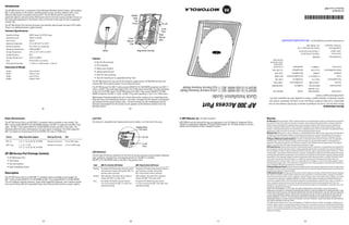

The AP 300 Access Port is a wireless access point that can be mounted on a wall or ceiling. It has two models - an 802.11a/b/g model and an 802.11b/g model. It receives power and transfers data through a single CAT-5 Ethernet cable, so no additional power supply is required. The document provides specifications, features, installation instructions, and regulatory information for the AP 300 Access Port.


