SlideShare a Scribd company logo
AUTOMOBILE ENGINEERING
Unit-II- ENGINE AUXILIARY
SYSTEMS
(CARBURETTOR)
By,
Dr.S.SURESH,
Assistant Professor,
Department of Mechanical Engineering
FUEL SUPPLY SYSTEMS
 The fuel passes through a number of stages before
reaching the combustion chamber.
 It includes the filtration and atomization of fuel into
fine particles.
 It is necessary to atomize the fuel before entering into
the combustion chamber so that complete combustion of
fuel can take place.
 There are different fuel supply systems for spark
ignition (petrol) and compression ignition (diesel)
engine.
FUEL SUPPLY SYSTEM OF SI ENGINE
 The combustible mixture of fuel is prepared outside the
combustion chamber.
 Proper air-fuel ratio is maintained with the help of a
device known as carburetor.
 The air fuel ratio depends upon the various conditions.
 The fuel from the tank is delivered to the float chamber
attached to the carburetor with the help of fuel pump.
 The fuel pump maintains the constant pressure. In
carburetor fuel is mixed with air in required proportion.
 After that the mixture of fuel and air is inducted into
the combustion chamber.
FUEL SUPPLY SYSTEM OF CI ENGINE
 In diesel engine only air is injected during the suction stroke and it is
compressed during compression stroke.
 Fuel is injected into the combustion chamber in the form of fine spray at
the end of compression stroke.
 A fuel injection system in a diesel engine has to satisfy the following
requirements:
1. To inject the fuel at the right time in the cycle.
2. The fuel should be properly atomized.
3. The correct quantity of fuel should be injected depending upon the
load.
 Fuel pump takes the fuel from fuel tank and delivers it to the fuel filter.
 When the pressure is developed in the injection pump the fuel flows
from
injection pump to the fuel injector under pressure.
CARBURETTOR
 Carburetion;
The process of formation of a combustible fuel-air mixture by mixing
the proper amount of fuel with air before admission to engine
cylinder is called carburetion and the device which does this job is
called a carburetor.
 Carburetor;
The carburetor is a device used for atomizing and vaporizing the
fuel and mixing it with the air in varying proportions to suit the
changing operating conditions of vehicle engines.
 Factors Affecting Carburetion
i. The engine speed
ii. The vaporization characteristics of the fuel
iii. The temperature of the incoming air and
iv. The design of the carburetor
PRINCIPLE OF CARBURETTOR
TYPES OF CARBURETOR
 1. According to the direction of flow.
a. Uplift carburetors or updraft carburetor
b. Down draft carburetor
c. Horizontal carburetor.
 2. According to the arrangement of the float chamber
a. Eccentric carburetor
b. Concentric carburetor.
 3. According to the number of units
a. Single carburetor
b. Double carburetor.
 4. According to the metering system
a. Air bled jet carburetor
b. Metering pin type carburetor.
 5. According to the type of venturi
a. Plain venturi carburetor
b. Double venturi carburetor
c. Vane venturi carburetor
d. Nozzle bar venturi carburetor
e. Triple venturi carburetor.
 6. According to the type of power system
a. Manually operated carburetor
b. Vacuum controlled carburetor.
SIMPLE CARBURETTOR
 It consists of a float chamber, fuel discharge nozzle,
venturi, throttle valve and choke.
 Simple carburettor consist of a venturi and a fuel
jet.
 For maintaining the level of fuel in the jet, a float
chamber is usually required.
 A throttle valve in the form of a flat circular metal
disc mounted on spindle is provided for controlling
the flow of air-fuel mixture to the induction
manifold. A rotary type valve also can be used
instead of disc type.
Construction and working...
 The level of fuel is just kept slightly below the top of
the jet to prevent the leakage when not in operation.
 Usually 1.5 mm difference is kept between the top of
the jet and the surface of the fuel in float chamber.
 A needle valve controls the passage of fuel from the
fuel pump, when the air begins to flow past the jet, a
low pressure zone is created in the venturi because of
the increased velocity of air.
 The fuel begins to rise because of the difference in the
air pressure on the fuel which is equal to the pressure of
the atmosphere and on the fuel in the jet at the venturi
and issue out from the jet in the form of fine spray. A
minute petrol particles present a large surface area being
exposed to the air stream. The fuel is not completely
vaporized in carburettor and some globules of fuel still
enter the induction manifold and are vaporized during the
compression stroke in engine cylinder. A choke valve
controls the flow of air into the carburettor. A gas tight
connection is provided between the carburettor and the
induction manifold.
 When two concentric venturies are provided, the discharge
end of the inner venturi called "Primary Venturi", which
lies just at the throat of the main venturi. A higher
velocity of air which aids in the atomization of the fuel, is
obtained at the throat of primary venturi due to lower
pressure comparing to main venturi.
DEFECTS IN THE SIMPLE CARBURETTOR
The simple carburettor, would work well if the engine
is running at one particular speed and load.
o The nozzle and the venturi sizes then can be set once
and the carburettor will then work satisfactorily at
that particular speed and load.
o But in actual practice, the engine has to run at
different speeds and loads ranging from the lowest to
the highest therefore certain irregularities creep in
the functioning of this simple carburettor.
1. STARTING DIFFICULTY
For starting, it is seen that very rich mixture is required,
but actually the mixture provided by the simple
carburettor will be very lean. The different methods to
provide for enrichment of fuel at very low speeds are :
(a) Ticklers:
These are devices used to cause flooding of
carburettor at the start.
(b) Choke:
This is a simple butterfly valve fitted at the top of air
horn. For starting, choke is closed so that very small
amount of air gets past it and the throttle valve is open
which delivers sufficient fuel to provide a mixture rich
in quality, though small in quantity.
ECCENTRIC CHOKE
TICKLERS
(C)Adjustable Area Jet:
A long tapered needle is used which is screwed into
the jet as shown in the figure. For starting the screw
is loosened so that the jet area providing fuel is
increased and thus rich mixture is provided for the
start.
2. IDLING DIFFICULTY
 During idling suction at the main nozzle is insufficient to draw
fuel from the chamber since throttle is closed.
 Therefore a separate supply circuit of fuel must be provided on
the engine side of the throttle valve during idling.
 This is done by providing a separate idle jet and an air bleed
hole, so that metered quantities of air and fuel are drawn into
the idle passage.
3. OPERATION AT DIFFERENT SPEEDS
 A simple carburettor provides richer mixture at high
speeds and leaner mixture at low speeds.
The process of adjusting the mixture strength at all
the speeds so that thought the whole range correct
proportions of air fuel mixture are maintained is
compensated.
 Various devices used for providing compensation are
Extra air valve
Compensating jet
Air bleed compensation
Multiple jet compensation
Suction controlled devices
 Extra Air valve • Compensating jet
•Air bleed compensation
 Multiple Jet Compensation
4. DIFFICULTY AT HIGH SPEEDS
 Weak air-fuel mixtures supplied by the single jet
carburettor will not give enough power at High speeds.
 A metering rod with stepped diameter end in the main jet
is used for this purpose.
 At high speeds metering rod is pulled up so that small
dia meter part is in the well supplying more fuel
5. ACCELERATION DIFFICULTY
When sudden acceleration is required, the throttle is
opened suddenly. This causes the maximum amount
of air to come at once but the fuel supply lags there
by causing ‘engine stumble’ or ‘ hesitation’ which is
due to weak mixture.
To avoid this a separate pump which provides fuel
momentarily till the rich mixture is delivered is
used.
6.INFLUENCE OF WEATHER

More Related Content

What's hot

Clutches for automobile
Clutches for automobile Clutches for automobile
Clutches for automobile
sgrsoni45
 
Clutch(single and multi plate)
Clutch(single and multi plate)Clutch(single and multi plate)
Clutch(single and multi plate)
10me027
 

What's hot (20)

Petrol engine vs diesel engine
Petrol engine vs diesel enginePetrol engine vs diesel engine
Petrol engine vs diesel engine
 
Clutches
ClutchesClutches
Clutches
 
Transmission system in an automobile
Transmission system in an automobileTransmission system in an automobile
Transmission system in an automobile
 
Flywheel in automobile
Flywheel in automobileFlywheel in automobile
Flywheel in automobile
 
Carburetors types
Carburetors typesCarburetors types
Carburetors types
 
Gear box
Gear boxGear box
Gear box
 
Types of Axles
Types of AxlesTypes of Axles
Types of Axles
 
Supercharging and Turbocharging
Supercharging and TurbochargingSupercharging and Turbocharging
Supercharging and Turbocharging
 
3 axles
3 axles3 axles
3 axles
 
2 fuel-supply-systems
2 fuel-supply-systems2 fuel-supply-systems
2 fuel-supply-systems
 
Classification of Automobiles
Classification of AutomobilesClassification of Automobiles
Classification of Automobiles
 
Propeller shaft & universal joint
Propeller shaft & universal jointPropeller shaft & universal joint
Propeller shaft & universal joint
 
Clutch
ClutchClutch
Clutch
 
Clutches for automobile
Clutches for automobile Clutches for automobile
Clutches for automobile
 
Clutch(single and multi plate)
Clutch(single and multi plate)Clutch(single and multi plate)
Clutch(single and multi plate)
 
Differential
DifferentialDifferential
Differential
 
Transmission system
Transmission systemTransmission system
Transmission system
 
slides on clutches
slides on clutchesslides on clutches
slides on clutches
 
Performance of ic engine
Performance of ic enginePerformance of ic engine
Performance of ic engine
 
Transmission Systems - Clutch
Transmission Systems - ClutchTransmission Systems - Clutch
Transmission Systems - Clutch
 

Similar to AUTOMOBILE ENGINEERING

SHREE RAMKRISHNA INSTITUTE OF SCIENCE & TECHNOLOGY (2).pptx
SHREE RAMKRISHNA INSTITUTE OF SCIENCE & TECHNOLOGY (2).pptxSHREE RAMKRISHNA INSTITUTE OF SCIENCE & TECHNOLOGY (2).pptx
SHREE RAMKRISHNA INSTITUTE OF SCIENCE & TECHNOLOGY (2).pptx
yahomithi
 

Similar to AUTOMOBILE ENGINEERING (20)

carburetion
carburetioncarburetion
carburetion
 
Carburetion
CarburetionCarburetion
Carburetion
 
MASTER_CARBURETION_1.ppt
MASTER_CARBURETION_1.pptMASTER_CARBURETION_1.ppt
MASTER_CARBURETION_1.ppt
 
Carburetion, injection and supercharging
Carburetion, injection and superchargingCarburetion, injection and supercharging
Carburetion, injection and supercharging
 
TYPES OF CARBURETORS
TYPES OF CARBURETORSTYPES OF CARBURETORS
TYPES OF CARBURETORS
 
Fuel injection system for si engines
Fuel injection system for si enginesFuel injection system for si engines
Fuel injection system for si engines
 
Carburetor.doc
Carburetor.docCarburetor.doc
Carburetor.doc
 
UNIT 3 -CHAP 3.pptx
UNIT 3 -CHAP 3.pptxUNIT 3 -CHAP 3.pptx
UNIT 3 -CHAP 3.pptx
 
Piston Engines: Fuel
Piston Engines: FuelPiston Engines: Fuel
Piston Engines: Fuel
 
IC Engines Fuel Systems PRINCIPLE AND WORKING
IC Engines Fuel Systems PRINCIPLE AND WORKINGIC Engines Fuel Systems PRINCIPLE AND WORKING
IC Engines Fuel Systems PRINCIPLE AND WORKING
 
SHREE RAMKRISHNA INSTITUTE OF SCIENCE & TECHNOLOGY (2).pptx
SHREE RAMKRISHNA INSTITUTE OF SCIENCE & TECHNOLOGY (2).pptxSHREE RAMKRISHNA INSTITUTE OF SCIENCE & TECHNOLOGY (2).pptx
SHREE RAMKRISHNA INSTITUTE OF SCIENCE & TECHNOLOGY (2).pptx
 
Carburetors
Carburetors Carburetors
Carburetors
 
Basic Carburetor Design
Basic Carburetor DesignBasic Carburetor Design
Basic Carburetor Design
 
Carburettor
CarburettorCarburettor
Carburettor
 
Unit 2.pdf
Unit 2.pdfUnit 2.pdf
Unit 2.pdf
 
UNIT-II-ENGINE AUXILIARY SYSTEMS &TURBOCHARGER
UNIT-II-ENGINE AUXILIARY SYSTEMS &TURBOCHARGERUNIT-II-ENGINE AUXILIARY SYSTEMS &TURBOCHARGER
UNIT-II-ENGINE AUXILIARY SYSTEMS &TURBOCHARGER
 
Automobile unit 2 carburetor
Automobile unit  2 carburetorAutomobile unit  2 carburetor
Automobile unit 2 carburetor
 
Automobile Engineering Unit 2 - Anna university
Automobile Engineering Unit 2 - Anna universityAutomobile Engineering Unit 2 - Anna university
Automobile Engineering Unit 2 - Anna university
 
carburetors-prv-160214151937.pdf
carburetors-prv-160214151937.pdfcarburetors-prv-160214151937.pdf
carburetors-prv-160214151937.pdf
 
Carburetors prv
Carburetors  prvCarburetors  prv
Carburetors prv
 

More from Dr.S.SURESH

More from Dr.S.SURESH (18)

SOM-Introduction.pdf
SOM-Introduction.pdfSOM-Introduction.pdf
SOM-Introduction.pdf
 
Strength of Materials-Shear Force and Bending Moment Diagram.pptx
Strength of Materials-Shear Force and Bending Moment Diagram.pptxStrength of Materials-Shear Force and Bending Moment Diagram.pptx
Strength of Materials-Shear Force and Bending Moment Diagram.pptx
 
Torsion (Springs)-Strength of Materials.pdf
Torsion (Springs)-Strength of Materials.pdfTorsion (Springs)-Strength of Materials.pdf
Torsion (Springs)-Strength of Materials.pdf
 
STRENGTH OF MATERIALS FOR MECHANICAL ENGINEERS-Unit-III-Torsion
STRENGTH OF MATERIALS FOR MECHANICAL ENGINEERS-Unit-III-Torsion STRENGTH OF MATERIALS FOR MECHANICAL ENGINEERS-Unit-III-Torsion
STRENGTH OF MATERIALS FOR MECHANICAL ENGINEERS-Unit-III-Torsion
 
Automobile Engineering-Unit-III-Transmission system of Automobile
Automobile Engineering-Unit-III-Transmission system of Automobile    Automobile Engineering-Unit-III-Transmission system of Automobile
Automobile Engineering-Unit-III-Transmission system of Automobile
 
Applied Hydraulics and Pneumatics- UNIT-II-Hydraulic System and Components
Applied Hydraulics and Pneumatics- UNIT-II-Hydraulic System and ComponentsApplied Hydraulics and Pneumatics- UNIT-II-Hydraulic System and Components
Applied Hydraulics and Pneumatics- UNIT-II-Hydraulic System and Components
 
Applied Hydraulics and Pneumatics - Unit-1- Fluid Power system and Fundamentals
Applied Hydraulics and Pneumatics - Unit-1- Fluid Power system and FundamentalsApplied Hydraulics and Pneumatics - Unit-1- Fluid Power system and Fundamentals
Applied Hydraulics and Pneumatics - Unit-1- Fluid Power system and Fundamentals
 
Automobile Engineering- Unit-3-Transmission system of Automobile (gear box)
Automobile Engineering- Unit-3-Transmission system of Automobile (gear box)Automobile Engineering- Unit-3-Transmission system of Automobile (gear box)
Automobile Engineering- Unit-3-Transmission system of Automobile (gear box)
 
Unit-3-Transmission system of Automobile
Unit-3-Transmission system of Automobile Unit-3-Transmission system of Automobile
Unit-3-Transmission system of Automobile
 
CE8395-STRENGTH OF MATERIALS FOR MECHANICAL ENGINEERS-Unit-III-Torsion (Springs)
CE8395-STRENGTH OF MATERIALS FOR MECHANICAL ENGINEERS-Unit-III-Torsion (Springs)CE8395-STRENGTH OF MATERIALS FOR MECHANICAL ENGINEERS-Unit-III-Torsion (Springs)
CE8395-STRENGTH OF MATERIALS FOR MECHANICAL ENGINEERS-Unit-III-Torsion (Springs)
 
Dynamics of Machines - Unit II-Balancing of Rotating Masses
Dynamics of Machines - Unit II-Balancing of Rotating MassesDynamics of Machines - Unit II-Balancing of Rotating Masses
Dynamics of Machines - Unit II-Balancing of Rotating Masses
 
Dynamics of Machines - Unit II-Balancing-Introduction
Dynamics of Machines - Unit II-Balancing-IntroductionDynamics of Machines - Unit II-Balancing-Introduction
Dynamics of Machines - Unit II-Balancing-Introduction
 
Dynamics of Machines - Unit II-Balancing of Reciprocating Masses
Dynamics of Machines - Unit II-Balancing of Reciprocating MassesDynamics of Machines - Unit II-Balancing of Reciprocating Masses
Dynamics of Machines - Unit II-Balancing of Reciprocating Masses
 
Dynamics of Machines - Unit III - Longitudinal Vibration
Dynamics of Machines - Unit III - Longitudinal VibrationDynamics of Machines - Unit III - Longitudinal Vibration
Dynamics of Machines - Unit III - Longitudinal Vibration
 
Dynamics of Machine - Unit III-Transverse Vibration
Dynamics of Machine - Unit III-Transverse VibrationDynamics of Machine - Unit III-Transverse Vibration
Dynamics of Machine - Unit III-Transverse Vibration
 
Dynamics of Machines - Unit III-Torsional Vibration
Dynamics of Machines -  Unit III-Torsional VibrationDynamics of Machines -  Unit III-Torsional Vibration
Dynamics of Machines - Unit III-Torsional Vibration
 
Dynamics of Machines - Unit V-Governors
Dynamics of Machines -  Unit V-GovernorsDynamics of Machines -  Unit V-Governors
Dynamics of Machines - Unit V-Governors
 
Dynamics of Machines- Unit IV-Forced Vibration
Dynamics of Machines- Unit IV-Forced VibrationDynamics of Machines- Unit IV-Forced Vibration
Dynamics of Machines- Unit IV-Forced Vibration
 

Recently uploaded

Hall booking system project report .pdf
Hall booking system project report  .pdfHall booking system project report  .pdf
Hall booking system project report .pdf
Kamal Acharya
 
Online blood donation management system project.pdf
Online blood donation management system project.pdfOnline blood donation management system project.pdf
Online blood donation management system project.pdf
Kamal Acharya
 
Standard Reomte Control Interface - Neometrix
Standard Reomte Control Interface - NeometrixStandard Reomte Control Interface - Neometrix
Standard Reomte Control Interface - Neometrix
Neometrix_Engineering_Pvt_Ltd
 

Recently uploaded (20)

Democratizing Fuzzing at Scale by Abhishek Arya
Democratizing Fuzzing at Scale by Abhishek AryaDemocratizing Fuzzing at Scale by Abhishek Arya
Democratizing Fuzzing at Scale by Abhishek Arya
 
ASME IX(9) 2007 Full Version .pdf
ASME IX(9)  2007 Full Version       .pdfASME IX(9)  2007 Full Version       .pdf
ASME IX(9) 2007 Full Version .pdf
 
Halogenation process of chemical process industries
Halogenation process of chemical process industriesHalogenation process of chemical process industries
Halogenation process of chemical process industries
 
İTÜ CAD and Reverse Engineering Workshop
İTÜ CAD and Reverse Engineering WorkshopİTÜ CAD and Reverse Engineering Workshop
İTÜ CAD and Reverse Engineering Workshop
 
Furniture showroom management system project.pdf
Furniture showroom management system project.pdfFurniture showroom management system project.pdf
Furniture showroom management system project.pdf
 
The Ultimate Guide to External Floating Roofs for Oil Storage Tanks.docx
The Ultimate Guide to External Floating Roofs for Oil Storage Tanks.docxThe Ultimate Guide to External Floating Roofs for Oil Storage Tanks.docx
The Ultimate Guide to External Floating Roofs for Oil Storage Tanks.docx
 
Hall booking system project report .pdf
Hall booking system project report  .pdfHall booking system project report  .pdf
Hall booking system project report .pdf
 
Architectural Portfolio Sean Lockwood
Architectural Portfolio Sean LockwoodArchitectural Portfolio Sean Lockwood
Architectural Portfolio Sean Lockwood
 
Toll tax management system project report..pdf
Toll tax management system project report..pdfToll tax management system project report..pdf
Toll tax management system project report..pdf
 
ENERGY STORAGE DEVICES INTRODUCTION UNIT-I
ENERGY STORAGE DEVICES  INTRODUCTION UNIT-IENERGY STORAGE DEVICES  INTRODUCTION UNIT-I
ENERGY STORAGE DEVICES INTRODUCTION UNIT-I
 
Cloud-Computing_CSE311_Computer-Networking CSE GUB BD - Shahidul.pptx
Cloud-Computing_CSE311_Computer-Networking CSE GUB BD - Shahidul.pptxCloud-Computing_CSE311_Computer-Networking CSE GUB BD - Shahidul.pptx
Cloud-Computing_CSE311_Computer-Networking CSE GUB BD - Shahidul.pptx
 
Quality defects in TMT Bars, Possible causes and Potential Solutions.
Quality defects in TMT Bars, Possible causes and Potential Solutions.Quality defects in TMT Bars, Possible causes and Potential Solutions.
Quality defects in TMT Bars, Possible causes and Potential Solutions.
 
WATER CRISIS and its solutions-pptx 1234
WATER CRISIS and its solutions-pptx 1234WATER CRISIS and its solutions-pptx 1234
WATER CRISIS and its solutions-pptx 1234
 
KIT-601 Lecture Notes-UNIT-3.pdf Mining Data Stream
KIT-601 Lecture Notes-UNIT-3.pdf Mining Data StreamKIT-601 Lecture Notes-UNIT-3.pdf Mining Data Stream
KIT-601 Lecture Notes-UNIT-3.pdf Mining Data Stream
 
Online blood donation management system project.pdf
Online blood donation management system project.pdfOnline blood donation management system project.pdf
Online blood donation management system project.pdf
 
NO1 Pandit Amil Baba In Bahawalpur, Sargodha, Sialkot, Sheikhupura, Rahim Yar...
NO1 Pandit Amil Baba In Bahawalpur, Sargodha, Sialkot, Sheikhupura, Rahim Yar...NO1 Pandit Amil Baba In Bahawalpur, Sargodha, Sialkot, Sheikhupura, Rahim Yar...
NO1 Pandit Amil Baba In Bahawalpur, Sargodha, Sialkot, Sheikhupura, Rahim Yar...
 
Standard Reomte Control Interface - Neometrix
Standard Reomte Control Interface - NeometrixStandard Reomte Control Interface - Neometrix
Standard Reomte Control Interface - Neometrix
 
Peek implant persentation - Copy (1).pdf
Peek implant persentation - Copy (1).pdfPeek implant persentation - Copy (1).pdf
Peek implant persentation - Copy (1).pdf
 
Construction method of steel structure space frame .pptx
Construction method of steel structure space frame .pptxConstruction method of steel structure space frame .pptx
Construction method of steel structure space frame .pptx
 
2024 DevOps Pro Europe - Growing at the edge
2024 DevOps Pro Europe - Growing at the edge2024 DevOps Pro Europe - Growing at the edge
2024 DevOps Pro Europe - Growing at the edge
 

AUTOMOBILE ENGINEERING

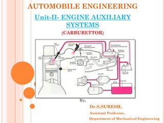
  • 1. AUTOMOBILE ENGINEERING Unit-II- ENGINE AUXILIARY SYSTEMS (CARBURETTOR) By, Dr.S.SURESH, Assistant Professor, Department of Mechanical Engineering
  • 2. FUEL SUPPLY SYSTEMS  The fuel passes through a number of stages before reaching the combustion chamber.  It includes the filtration and atomization of fuel into fine particles.  It is necessary to atomize the fuel before entering into the combustion chamber so that complete combustion of fuel can take place.  There are different fuel supply systems for spark ignition (petrol) and compression ignition (diesel) engine.
  • 3. FUEL SUPPLY SYSTEM OF SI ENGINE
  • 4.  The combustible mixture of fuel is prepared outside the combustion chamber.  Proper air-fuel ratio is maintained with the help of a device known as carburetor.  The air fuel ratio depends upon the various conditions.  The fuel from the tank is delivered to the float chamber attached to the carburetor with the help of fuel pump.  The fuel pump maintains the constant pressure. In carburetor fuel is mixed with air in required proportion.  After that the mixture of fuel and air is inducted into the combustion chamber.
  • 5. FUEL SUPPLY SYSTEM OF CI ENGINE
  • 6.  In diesel engine only air is injected during the suction stroke and it is compressed during compression stroke.  Fuel is injected into the combustion chamber in the form of fine spray at the end of compression stroke.  A fuel injection system in a diesel engine has to satisfy the following requirements: 1. To inject the fuel at the right time in the cycle. 2. The fuel should be properly atomized. 3. The correct quantity of fuel should be injected depending upon the load.  Fuel pump takes the fuel from fuel tank and delivers it to the fuel filter.  When the pressure is developed in the injection pump the fuel flows from injection pump to the fuel injector under pressure.
  • 7. CARBURETTOR  Carburetion; The process of formation of a combustible fuel-air mixture by mixing the proper amount of fuel with air before admission to engine cylinder is called carburetion and the device which does this job is called a carburetor.  Carburetor; The carburetor is a device used for atomizing and vaporizing the fuel and mixing it with the air in varying proportions to suit the changing operating conditions of vehicle engines.  Factors Affecting Carburetion i. The engine speed ii. The vaporization characteristics of the fuel iii. The temperature of the incoming air and iv. The design of the carburetor
  • 9. TYPES OF CARBURETOR  1. According to the direction of flow. a. Uplift carburetors or updraft carburetor b. Down draft carburetor c. Horizontal carburetor.  2. According to the arrangement of the float chamber a. Eccentric carburetor b. Concentric carburetor.  3. According to the number of units a. Single carburetor b. Double carburetor.  4. According to the metering system a. Air bled jet carburetor b. Metering pin type carburetor.  5. According to the type of venturi a. Plain venturi carburetor b. Double venturi carburetor c. Vane venturi carburetor d. Nozzle bar venturi carburetor e. Triple venturi carburetor.  6. According to the type of power system a. Manually operated carburetor b. Vacuum controlled carburetor.
  • 10. SIMPLE CARBURETTOR  It consists of a float chamber, fuel discharge nozzle, venturi, throttle valve and choke.
  • 11.  Simple carburettor consist of a venturi and a fuel jet.  For maintaining the level of fuel in the jet, a float chamber is usually required.  A throttle valve in the form of a flat circular metal disc mounted on spindle is provided for controlling the flow of air-fuel mixture to the induction manifold. A rotary type valve also can be used instead of disc type. Construction and working...
  • 12.  The level of fuel is just kept slightly below the top of the jet to prevent the leakage when not in operation.  Usually 1.5 mm difference is kept between the top of the jet and the surface of the fuel in float chamber.  A needle valve controls the passage of fuel from the fuel pump, when the air begins to flow past the jet, a low pressure zone is created in the venturi because of the increased velocity of air.
  • 13.  The fuel begins to rise because of the difference in the air pressure on the fuel which is equal to the pressure of the atmosphere and on the fuel in the jet at the venturi and issue out from the jet in the form of fine spray. A minute petrol particles present a large surface area being exposed to the air stream. The fuel is not completely vaporized in carburettor and some globules of fuel still enter the induction manifold and are vaporized during the compression stroke in engine cylinder. A choke valve controls the flow of air into the carburettor. A gas tight connection is provided between the carburettor and the induction manifold.  When two concentric venturies are provided, the discharge end of the inner venturi called "Primary Venturi", which lies just at the throat of the main venturi. A higher velocity of air which aids in the atomization of the fuel, is obtained at the throat of primary venturi due to lower pressure comparing to main venturi.
  • 14. DEFECTS IN THE SIMPLE CARBURETTOR The simple carburettor, would work well if the engine is running at one particular speed and load. o The nozzle and the venturi sizes then can be set once and the carburettor will then work satisfactorily at that particular speed and load. o But in actual practice, the engine has to run at different speeds and loads ranging from the lowest to the highest therefore certain irregularities creep in the functioning of this simple carburettor.
  • 15. 1. STARTING DIFFICULTY For starting, it is seen that very rich mixture is required, but actually the mixture provided by the simple carburettor will be very lean. The different methods to provide for enrichment of fuel at very low speeds are : (a) Ticklers: These are devices used to cause flooding of carburettor at the start. (b) Choke: This is a simple butterfly valve fitted at the top of air horn. For starting, choke is closed so that very small amount of air gets past it and the throttle valve is open which delivers sufficient fuel to provide a mixture rich in quality, though small in quantity.
  • 17. (C)Adjustable Area Jet: A long tapered needle is used which is screwed into the jet as shown in the figure. For starting the screw is loosened so that the jet area providing fuel is increased and thus rich mixture is provided for the start.
  • 18. 2. IDLING DIFFICULTY  During idling suction at the main nozzle is insufficient to draw fuel from the chamber since throttle is closed.  Therefore a separate supply circuit of fuel must be provided on the engine side of the throttle valve during idling.  This is done by providing a separate idle jet and an air bleed hole, so that metered quantities of air and fuel are drawn into the idle passage.
  • 19. 3. OPERATION AT DIFFERENT SPEEDS  A simple carburettor provides richer mixture at high speeds and leaner mixture at low speeds. The process of adjusting the mixture strength at all the speeds so that thought the whole range correct proportions of air fuel mixture are maintained is compensated.  Various devices used for providing compensation are Extra air valve Compensating jet Air bleed compensation Multiple jet compensation Suction controlled devices
  • 20.  Extra Air valve • Compensating jet •Air bleed compensation
  • 21.  Multiple Jet Compensation
  • 22. 4. DIFFICULTY AT HIGH SPEEDS  Weak air-fuel mixtures supplied by the single jet carburettor will not give enough power at High speeds.  A metering rod with stepped diameter end in the main jet is used for this purpose.  At high speeds metering rod is pulled up so that small dia meter part is in the well supplying more fuel
  • 23. 5. ACCELERATION DIFFICULTY When sudden acceleration is required, the throttle is opened suddenly. This causes the maximum amount of air to come at once but the fuel supply lags there by causing ‘engine stumble’ or ‘ hesitation’ which is due to weak mixture. To avoid this a separate pump which provides fuel momentarily till the rich mixture is delivered is used.