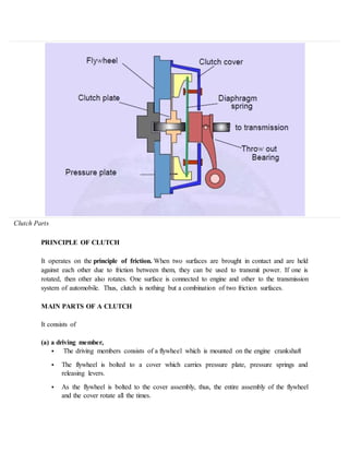
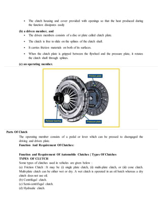
SlideShare a Scribd company logo
UNIT 3
CLUTCHES:
INTRODUCTION TO TRANSMISSION :
Transmission is the mechanism which is used to transfer the power developed by engine to the
wheels of an automobile. The transmission system of an automobile includes clutch, gear box,
propeller shaft axle and wheels, etc.
Description of various types of clutches and gear boxes has been given in the following sections
of this unit. The term ‘Transmission’ is used for a device which is located between clutch and
propeller shaft. It may be a gear box, an over drive or a torque converter, etc.
INTRODUCTION TO CLUTCH
Clutches are useful in devices that have two rotating shafts. In these devices, one of the shafts is
typically driven by a motor or pulley, and the other shaft drives another device. In a drill, for
instance, one shaft is driven by a motor and the other drives a drill chuck. The clutch connects
the two shafts so that they can either be locked together and spin at the same speed, or be
decoupled and spin at different speeds.
In a car, you need a clutch because the engine spins all the time, but the car's wheels do not. In
order for a car to stop without killing the engine, the wheels need to be disconnected from the
engine somehow. The clutch allows us to smoothly engage a spinning engine to a non-spinning
transmission by controlling the slippage between them.
To understand how a clutch works, it helps to know a little bit about friction, which is a measure
of how hard it is to slide one object over another. Friction is caused by the peaks and valleys that
are part of every surface -- even very smooth surfaces still have microscopic peaks and valleys.
The larger these peaks and valleys are, the harder it is to slide the object. You can learn more
about friction in How Brakes Work.
A clutch works because of friction between a clutch plate and a flywhee
Clutch Parts
PRINCIPLE OF CLUTCH
It operates on the principle of friction. When two surfaces are brought in contact and are held
against each other due to friction between them, they can be used to transmit power. If one is
rotated, then other also rotates. One surface is connected to engine and other to the transmission
system of automobile. Thus, clutch is nothing but a combination of two friction surfaces.
MAIN PARTS OF A CLUTCH
It consists of
(a) a driving member,
 The driving members consists of a flywheel which is mounted on the engine crankshaft
 The flywheel is bolted to a cover which carries pressure plate, pressure springs and
releasing levers.
 As the flywheel is bolted to the cover assembly, thus, the entire assembly of the flywheel
and the cover rotate all the times.
 The clutch housing and cover provided with openings so that the heat produced during
the function dissipates easily
(b) a driven member, and
 The driven members consists of a disc or plate called clutch plate.
 The clutch is free to slide on the splines of the clutch shaft.
 It carries friction materials on both of its surfaces.
 When the clutch plate is gripped between the flywheel and the pressure plate, it rotates
the clutch shaft through splines.
(c) an operating member.
Parts Of Clutch
The operating member consists of a pedal or lever which can be pressed to disengaged the
driving and driven plate.
Function And Requirement Of Clutches:
Function and Requirement Of Automobile Clutches | Types Of Clutches
TYPES OF CLUTCH
Some types of clutches used in vehicles are given below :
(a) Friction Clutch : It may be (i) single plate clutch, (ii) multi-plate clutch, or (iii) cone clutch.
Multi-plate clutch can be either wet or dry. A wet clutch is operated in an oil batch whereas a dry
clutch does not use oil.
(b) Centrifugal clutch.
(c) Semi-centrifugal clutch.
(d) Hydraulic clutch.
(e) Positive clutch.
(f) Vacuum clutch.
(g) Electromagnetic clutch.
CONE CLUTCH:
In the cone clutch the contact surfaces of the driving and driven members are made as portions of
cones. A typical cone clutch is show in the picture
The flywheel is attached to the crankshaft by bolts passing through the web of the flywheel and a
flange integral with the crankshaft. This male member is which made in two parts. The cone part
is bolted to the centre flange splined on the driven shaft. This allows the cone to be made of
aluminium and the centre is made of steel. This makes the cone to be lighter and the centre to
have the necessary strength. The composite male member is carried on the crankshaft spigot,
with a bush provided between them. The male cone member is attached to the gear box input
shaft. A spring presses the male cone into the female cone of the fly wheel. The spring reaction is
taken through a ball thrust bearing onto the clutch cover plate. The clutch cover plate is bolted to
the rim of the flywheel by means of a number of hexagon headed screws.
To disengage the clutch, the male cone is drawn back along the spigot against the pressure of the
spring. The faces of the cones are then separated. Now the engine flywheel no longer drives the
male cone, and hence the driven shaft, i.e., gearbox input shaft.
Using cones for the engaging surfaces enables greater torque to be transmitted without having to
employ extremely heavy clutch springs.The angle of the cones cannot be made much smaller
than about 20°. Because with a very small cone angle, the male cone will bind or stick in the
female cone and it will be difficult to disengage the clutch. Further, a small quantity of wear on
the cone surfaces will result in a considerable axial movement of the cone.Cone clutches are
generally used in the synchromesh mechanisms in constant mesh gearboxes.
SINGLE PLATE CLUTCH:
Clutch Engage Clutch Dis Engage
 It is the most common type of clutch used in motor vehicles. Basically, it consists of only
one clutch plate, mounted on the splines of the clutch shaft.
 It transmits engine power to the gearbox, and allows transmission to be interrupted while
a gear is selected to move off from a stationary position, or when gears are changed while
the car is moving.
 Most cars use a friction clutch operated either by fluid (hydraulic) or, more commonly,
by a cable.
 When a car is moving under power, the clutch is engaged. A pressure plate bolted to
the flywheel exerts constant force, by means of a diaphragm spring, on the driven plate.
 Earlier cars have a series of coil springs at the back of the pressure plate, instead of a
diaphragm spring.
 The driven (or friction) plate runs on a splined input shaft, through which the power is
transmitted to the gearbox. The plate has friction linings, similar to brake linings, on both
its faces. This allows the drive to be taken up smoothly when the clutch is engaged.
 When the clutch is disengaged (pedal depressed), an arm pushes a release bearing against
the centre of the diaphragm spring which releases the clamping pressure.
 The outer part of the pressure plate, which has a large friction surface, then no longer
clamps the driven plate to the flywheel, so the transmission of power is interrupted and
gears can be changed.
 When the clutch pedal is released, the thrust bearing is withdrawn and the diaphragm-
spring load once again clamps the driven plate to the flywheel to resume the transmission
of power.
 Some cars have a hydraulically operated clutch. Pressure on the clutch pedal inside the
car activates a piston in a master cylinder, which transmits the pressure through a fluid-
filled pipe to a slave cylinder mounted on the clutch housing.
 The slave-cylinder piston is connected to the clutch release arm.
 Parts of the clutch
 The modern clutch has four main components: the cover plate (which incorporates a
diaphragm spring), the pressure plate, the driven plate, and the release bearing.
 The cover plate is bolted to the flywheel, and the pressure plate exerts pressure on the
driven plate through the diaphragm spring or through coil springs on earlier cars.
 The driven plate runs on a splined shaft between the pressure plate and flywheel.
 It is faced on each side with a friction material which grips the pressure plate and
flywheel when fully engaged, and can slip by a controlled amount when the clutch pedal
is partially depressed, allowing the drive to be taken up smoothly.
 The release bearing is pushed hard against the diaphragm spring, either hydraulically or
by a cable and lever, and releases spring load to interrupt power transmission.
MULTI PLATE CLUTCH:
A multiple plate clutch has more number of clutch plates. A typical clutch consist of the
following components: Clutch basket or cover, clutch hub, drive (friction) plates, driven (steel)
plates, pressure plate and the clutch springs. The clutch housing is attached to the engine crank
shaft flywheel. The pressure plate is fixed on the flywheel through the clutch springs. The engine
flywheel turns the clutch housing. The inner circumference of the clutch basket is splined to
carry the thin metal plates. The clutch basket splines engage the tabs on the friction drive plates.
This sources the clutch housing and the drive plates to rotate together. Additionally they are free
to slide axially within the clutch basket.
Interleaved with the drive plates, there are many number of driven plates. These driven friction
plates have inner splines. These splines engage with the outer splines on the clutch hub. As such,
the driven friction plates can slide on the clutch hub. The clutch hub is linked to the input shaft of
the transmission gear box.
The drive plates and the driven plates are firmly pressed together by the pressure plate due to the
clutch springs. The drive plates, driven plates and the strong clutch coil springs are assembled
within the clutch basket.
Working:
During clutch engagement, spring pressure forces the pressure plate towards engine flywheel.
This causes the friction plates and the steel driven plates to be held together. Friction locks them
together tightly. Then the clutch basket, drive plates, driven plates, clutch hub and the gearbox
input shaft all spin together as one unit. Now power flows from the clutch basket through the
plates to the inner clutch hub and into the main shaft of the transmission.
The clutch gets released or disengaged when the clutch pedal is pressed. This causes the clutch
pressure plate to be moved away from the drive and driven plates, overcoming the clutch spring
force. This movement of the pressure plate, relieves the spring pressure holding the drive and
driven plates together. Then the plates float away from each other and slip axially. Thus, the
clutch shaft speed reduces slowly. Finally, the clutch shaft stops rotating. Power is no longer
transferred into the transmission gearbox.
Multiple plate clutches are used widely in motor cycles and scooters. The multiple plate clutch is
used in some types of epicycle gearboxes. A multiple plate clutch provides a very compact, yet a
high friction coupling between the engine and the gearbox. With multiple plates, the friction
surface area, strength and friction in the engaged clutch are increased. The increased friction
surfaces, increases the torque transmission capacity of the clutch.
Depending upon the power output of the engine, and the weight of the vehicle, four to eight sets
of plates (four to eight drive plates and four to eight driven plates) may be housed in the clutch
basket.
The multiple plate clutch may be of dry type or wet type. When the clutch functions in
atmosphere, it is called a dry clutch. When the clutch operates in an oil bath, it is named as a wet
clutch.
Some multiple plate clutches work dry. Then the driving plates are lined on each side with a
friction fabric. A dry clutch can withstand high temperatures and permits frequent gear shifts
without much loss of power initiated by heat. A dry clutch should never come in contact with oil.
In dry clutches, seals are used to inhibit entry of oil into the clutch basket. Oil will source clutch
slippage and will ruin the clutch friction discs
Most multiple clutches run in an oil bath. Wet clutches are used for several reasons: Debris
resulting from clutch wear can be drained with the oil and trapped by the oil filter. Oil helps the
clutch to run cool. In the case of two wheelers, since the primary drive requires lubrication, it is
less costly to use a wet clutch.
A wet clutch operates smoother and uses more plates. Some clutches have alternative steel and
bronze plates running in an oil bath and are quire smaller in diameter for minimal inertia.
MAGNETIC CLUTCH:
Electromagnetic Clutch Principle:
Before discussing about electromagnetic clutch first you
should know about basic fundamentals of clutch. Clutch is a device which engage or
disengage two shafts called driving shaft or engine shaft and driven shaft or
gear box shaft. A simple basic clutch consist two pressure plates, one is
connected with engine shaft and other one with gearbox. The pressure force
is applied by the spring arrangement which forced these plates towards each
other when the clutch pedal is not pressed. There is a friction plate between
both of these pressure plates. When the engine shaft rotates, it makes rotate the
gear shaft due to friction force between them. When the driver press the clutch
pedal, both pressure plate loose contact with each other and clutch is in
disengage position.
This is basic of any clutch. All friction clutches work on
same principle. An electromagnetic clutch is also a friction clutch but it
uses magnetic force in place of spring force to engage and disengage the
clutch. It also consist two clutch plates (Rotor and Hub). One of them is connected with the
electric circuit. When the electricity passes through this plate, it converts it
into electromagnet which attract the other plate towards it. There is also
a friction plate between them. The magnetic field apply force to connect both these plates and
friction plate transmit torque between them. Thus this clutch is combination
of both electromagnetic effect and mechanical clutch. Now we will discuss construction and
working of this clutch.
Construction:
This clutch consists following parts.
Rotor:
Rotor is a major part of this clutch witch is connected directly to the driving shaft or engine
shaft. It continuously rotate along with the driving shaft.
Winding or Coil:
Winding coil is situated behind the rotor and remains in
stationary position during clutch working. It is shown in figure. A high
voltage DC supply is connected with this winding which transfer a high voltage
current into this winding and convert it into electromagnet.
Armature:
Armature is situated at front of the rotor. It is connected to the hub or pressure plated with the
help or rivet or bolted joint.
Hub:
Hub or pressure plate is bolted with the gear shaft or driven shaft and rotates with it. It is situated
after the armature.
Friction Plate:
Friction plate is inserted between armature and rotor according to the requirement.
Supply unit:
Supply unit consist clutch switch, battery, wire etc.
Working:
The electromagnetic clutch working can be summarized into following points.
 In the initial condition the clutch is in disengage position. There is an air gap between
rotor and hub.
 First the engine starts which makes rotate the rotorconnected with the engine shaft.
 A DC battery supplies DC current into the clutch winding.
 This high voltage DC current converts this winding into an electromagnet which attract
armature towards it.
 This armature force friction plate towards the rotor and make rotate the hub.
 Thus the hub rotate and the rotor transmit 100 percent torque during engage position.
 When the clutch switch / pedal is pressed, the battery stops
the supply in winding which remove the electromagnetic force, thus the clutch
is in disengage position.
Advantages:
 No linkage is required to operate the clutch. So it can be installed any remote location.
 It can be used to achieve automatic transmission.Easy to operate.
 Less wear and tear at contactpoint.
Disadvantages:
 This clutch operating temperature is limited by the temperature rating of the insulating
material.
 High initial Cost.
CENTRIFUGAL CLUTCH:
A simple basic clutch has two plates, the first one is connected with
driving shaft or flywheel of engine and the other one is with driven shaft.
These shaft remains in contact in primary condition and transfer torque from
driving member to driven member through friction. The initial force due to
which these both plates remains in contact achieve by springs. When the driver
press the clutch pedal, both these plates loose its contact and at this point
clutch is in disengage position. At this point no power is transfer from
driving member to driven member until the driver release the clutch pedal.
All friction clutch works on same principle. In centrifugal
clutch the initial force which are used to engage the clutch is achieve by
centrifugal action or centrifugal force. This centrifugal force automatically
engage the clutch at a predefine speed and disengage it when the engine slow
down below a limit.
Till now We have learnt about basic idea of centrifugal
clutch. We will learn about construction and practical working of this clutch
in later portion of this article.
Construction:
The centrifugal clutch consists following parts. I highly
recommend to read the below diagram during reading about its construction.
Spider or Guide:
Spider or guide is works as one of the pressure plate of
simple clutch. It is connected to the driving shaft of engine. It is called
guide way because it hold the shoe and guide its movement. The initial position
of shoe in the guide is controlled by the springs.
Drum:
Drum act like the another pressure plate of a simple clutch.
It is connected with the driven member and rotate with it. Drum does not
directly connected with the guide or shoe.
Shoe:
Shoe is major part of centrifugal clutch. It act like
engaging member of guide and drum during running condition. When the driving
shaft rotate, it makes rotate the shoe which are free to move in guide. Due to
rotation a centrifugal action works on it which force it outward and connect
with drum.
Springs:
Springs are controlling element of this type of clutch. Each
shoe require one spring. The shoe are connected with the guide through these
springs. It hold the shoe at its initial position unlit driving member achieve
the required speed at which the centrifugal force can overcome spring force. If
we want to change the engaging speed of the clutch, we simply change these
springs with higher spring indexed springs.
Friction Lining:
The outer face of the shoe which is going to connect with
drum is equipped with friction lining. These lining play the same role which
friction plate play in simple clutch. It is used to transmit torque from
driving member to driven member and also avoid direct contact of shoe through
drum which reduce wear and tear of shoe.
Working:
Now you have understand purpose and construction of
centrifugal clutch. I think you have also got the idea of its working. We can
summarize it in following point.
 At the initial condition when the engine is off the shoe are
not connected with the drum.
 As the engine start, the Spider or Guide attached with
engine shaft start to rotate.
 The shoe connected with the spider also rotate with it and
felt some centrifugal action. This centrifugal force makes shoe to slide in the
direction of circumference.
 At low speed, the centrifugal force is too low to
overcome the spring force which tend to bound the shoe inside the guide.
 As the speed increases the shoe move outside and make a
contact with drum. The friction lining between shoe and drum start to transfer
torque from engine to drum.
 Now the drum start to rotate and as the speed of engine
increase, it will increase the centrifugal force and also the efficiency of
torque transmission through centrifugal action.
 When the engine speed decrease, will decrease the
centrifugal action which remove the contact of drum and shoe and disengage the
clutch.
 Thus this is an automatically speed
operated clutch. The operating speed of clutch can be maintained by replacing
spring.
Advantages:
 It is low in price.
 Easy to operate.
 It doesn’t require any separate control mechanism like clutch pedal etc.
 The engaging speed can be preciously controlled by selecting springs.
 It is used for automating transmission in which the driver first select gear and then press
the accelerator pedal.
 It requires less maintenance.
Disadvantages:
 Power transmission is limited due to slippage.
 It cannot used to transmit high amount of torque.
 The power transmission or speed regulation is totally depended on controlling speed.
 Overheating problem due to quick engagement during running condition.
Application:
 It is used in chain saw, lawn mower etc.
 It is used in textile industries.
Fluid flywheel or fluid coupling:
 A liquid coupling is used to transmit engine turning effort (torque) to a clutch and
transmission. The coupling is always a major part of the engine flywheel assembly. As
such it is sometime called a fluid flywheel.
 Construction of flywheel
 The fluid flywheel details can be seen in the picture. It consists of two half dough nut
shaped shells equipped with interior fins. The fins radiate from the hub, and thereby form
radial passages. The areas of these passages, perpendicular to their centre line, are kept
constant by a suitable design. Since the circumferential width of the opening close to the
hub is less than that at the periphery, the radial size of the opening, close to the hub is
made greater than that at the periphery.
 One of the shells is fixed to the crankshaft of the engine and the other to the
clutch/gearbox shaft. The two shells are mounted very close, with their open ends facing
each other, so that they can be turned independently without touching. Housing surrounds
both units to make a closed assembly. About 80 percent of the interior of the assembly is
filled with oil.
Working of fluid flywheel:
 The driving unit, called impeller, is linked to the engine crankshaft. When the engine
throttle is opened, the oil in the impeller starts moving. Due to the force of the rotating,
trapped oil impinges on the fins of the driven unit called runner and causes it to move. In
this way, the moving liquid transmits the engine power to the clutch driving plat or to any
other unit to which the runner is attached. This happens without any metal contact.
 In the actual units, the runner speed becomes almost equal to that of the impeller only
under the best operating conditions, when the efficiency of liquid coupling is highest. But
usually the runner speed is less than that of the impeller. The (speed) lag of the runner
behind the impeller is known as slip. This (speed) slip varies with many factors such as
engine speed, vehicle speed and engine and vehicle load.
 The slip is greatest with the vehicle at rest (ie runner stationary), and the engine throttle
being opened to cause the impeller to start circulating the oil. Under these conditions, the
oil moves in two general directions at the same time. It rotates at right angles to the
shafts, i.e., undergoes rotary flow. The oil also circulates between the impeller and
runner, i.e., undergoes vortex flow. When the rotary flow attains sufficient force and
volume, it causes the movement of the runner.
 The vortex flow is at right angles to the rotary flow. The vortex flow is produced by the
oil trapped in the fins of the impeller. The oil flies out against the curved interior, because
of centrifugal force. The centrifugal force directs the oil across to the runner, thereby
returning it to the impeller in the region of the hub.
 The vortex flow is maximum when the slip is 100 percent (runner stationary), and
decreases as the runner speed approaches that of the impeller. This results from the
centrifugal force produced by the oil in the runner, which moves out and opposes the
vortex flow. At cruising speeds, there is little or no vortex flow because the centrifugal
forces produced in the impeller and runner are almost equal. As such, the efficiency of
coupling increases rapidly from zero at rest to nearly 99 percent at higher speeds.
 The torque or turning effort delivered to the runner through the liquid is equal to the
torque applied to the impeller by the engine. But the power (ie the rate at which the
energy is furnished) received by the runner is always less than that furnished by the
engine. The power losses in the coupling appear as heat, which is dissipated as the
assembly revolves.
Advantages of fluid flywheel
 An ordinary friction clutch would be damaged by prolonged slipping, with increased fuel
consumption. But by prolonged slipping, the fluid flywheel will not suffer any
mechanical damage although it may become so hot as to burn one’s hand if one touched
it.
 When a liquid coupling is used with a conventional clutch and transmission, it enables
the driver to use the clutch and gears with less skill and fatigue than with an all
mechanical linkage. Unskillful clutch engagement or selection of the improper gear will
not produce any chattering and bucking. Any sudden load is cushioned and absorbed by
the coupling so that dynamic stresses on the gear teeth of the transmission and rear
(drive) axle are greatly reduced.
 Liquid coupling at low speeds are not as efficient as mechanical clutch. As such it
reduces engine braking when slowing down the vehicle speed, particularly during coming
down a hilly track, Further, it requires higher speeds to start a vehicle by pushing or
towing it.
SLIDING MESH GEAR BOX:
Sliding mesh gearbox is a transmission system that consists of various sets of gears and shafts
that are arranged together in an organised fashion and the shifting or meshing of different gear
ratios is done by the sliding of gears towards right and left over the splined shaft with the help of
a gear lever operated by the driver.
Need of Sliding Mesh Transmission
Introduction of an IC engine had led to the introduction of an automobile that was the
replacement of the horse carriage which was used as the travelling medium by the people in early
18th century, but still the automobile was lacking behind when it came to face the challenges
(turns, elevations, roughness etc.) given by the the roads as there was no such mechanism fitted
in early vehicles that could provide different torque and speed ratios as demanded by the road
conditions.
In 1894 the first transmission system named Sliding mesh transmission system was introduced
which was designed to provide different speed and torque ratios to overcome those road
challenges.
The various problem solved by this types of gearbox are-
 Fuel consumption of an automobile increased as the load on the engine is decreased or shared by
the intermediate system known as sliding mesh gearbox.
 Due to the varying torque ratios provided by this gearbox, the automobile vehicle is made to go
to the hill stations which was not possible earlier.
 Time taken to reach the destination was decreased as overall speed of the vehicle increased due
to the high speed ratios provided by it.
 Reverse of the car made possible with the introduction of this transmission system.
 Jamming of vehicle due to the rough road conditions was solved after the introduction of the
sliding mesh gear box.
Components of a Sliding Mesh Gearbox
(i) Shafts – Sliding mesh gearbox consists of 3 shafts that are-
1. Main shaft- It is the shaft used as an output shaft in a sliding-mesh over which the sets of gears
with internally splined grooves are arranged in an organised fashion. The outer surface of this
shaft is made splined so that the gears can easily slide over this shaft in order to mesh with the
appropriate gear.
2. Clutch shaft- It is the shaft that is used to carry engine output to the transmission box with the
help of engaging and disengaging clutch which is mounting at the engine end, gear or a pair of
gear is mounted over this shaft which is used to transmit rotational motion to the lay shaft.
3. Lay shaft- It is the shaft having gears mounted over its outer surface and is in continuous
rotation with the clutch shaft as one gear of this shaft is always in contact with a gear on the
clutch shaft, it is used as a intermediate shaft( between main shaft and clutch shaft )that provides
the meshing of the gears of the main shaft in order to transmit appropriate output to the final
drive.
(ii) Gears – 2 types of gear were usually used in sliding mesh gearbox.
1. Spur gear- This is the type of gears having straight cut teethes over its surface, straight teethes
proving maximum meshing area.
2. Helical gear- This is the type of gear in which the teethes are cutted in angular fashion unlike
spur gears this type of gears are smooth and less noisy.
(iii) Gear lever- It is the selecting mechanism operated by the driver in order to select the
appropriate gear ratio, this liver is connected to the main shaft along with the selector forks.
Working of Sliding Mesh Gearbox
The shifting of gears is obtained by the meshing of the gears on the main shaft with the gears on
the lay shaft by right or left sliding of gears on the main shaft in order to obtain appropriate
gears, lets understand the working of 3- speed 1-reverse transmission used in early automobile
vehicles.
First gear
First gear provide maximum torque at low speed which is obtained when the smallest gear on the
lay shaft meshes with the biggest gear on the main shaft in order to provide high torque .
Second gear
Second gear provides less torque and higher speed than first gear and is obtained when the
middle size gear of the main shaft meshes with the second smallest gear on the lay shaft and high
speed and second high torque is transmitted to the final drive.
Third gear
Third gear provides maximum speed and minimum torque to the final drive and is also known as
high speed gear or top gear in sliding mesh gearbox , this gear is obtained when the smallest
gear of the main shaft meshes with the biggest gear of the lay shaft. Or we can say that the drive
obtained maximum speed of the clutch shaft.
Reverse gear
When the reverse gear is selected, the rotation of the output shaft is reversed which is made
possible by using an idler gear between the main shaft and lay shaft that changes the rotation of
the output shaft and the vehicle starts moving in reverse direction.
Application
It is the oldest type of gearbox used in early 19s models of cars.. Some of them are-
1. Alfa 12HP used sliding mesh gearbox with 4 -speed manual transmission.
2. Fiat 6HP used 3-speed manual transmission.
3. Mercedes 35HP used 4-speed manual transmission
4. Renault Voiturette used manual 3-speed transmission.
CONSTANT MESH GEAR BOX:
The introduction of first transmission system i.e. sliding mesh transmission was a great success
in automobiles industry as now there was a system which can provide required torque and speed
ratios need by the vehicle to face the road challenges but still there were many important
problems with this transmission system which raised question on its effectiveness and reliability.
The problems faced were as follows-
 The shifting of gears was not an easy task as the shifting required special technique which were
not at all everybody’s cup of tea, a skilled driver was required for driving such vehicle, the
special technique required was Double-de-clutching.
Note – Double-de-clutching- it is the technique as the name indicates that required double
engagement and disengagement of clutch for shifting a single gear.
i.e. When driver wants to shift the gear he first presses the clutch pedal and bring the gear to the
neutral, than again he releases the clutch pedal and accelerate in order to increase the speed of
the lay-shaft so that the meshing of appropriate gear can occur, then again he presses the clutch
pedal and bring the gear liver to the required gear and release the clutch pedal and finally the
required gear is obtained.
 Since, the gears is to be meshed are in continuous rotation with different speed so the meshing of
these gears can cause breakage to the gear teethes or continuous wear and tear is there.
 The shifting of gears is a very noisy process.
 High maintenance is required as sliding and meshing of gears causes frictional wear of shafts and
gears.
Construction or Main Components
The construction or main components of constant mesh gearbox are:
1. Shafts – Same as sliding mesh 3 shafts are there-
(i) Main shaft- Also known as the output shaft, the splined shaft over which the dog clutches
along with gears are mounted.
(ii) Lay shaft- An intermediate shaft over which the gears which are in constant mesh with main
shaft gears are mounted.
(iii) Clutch shaft- Same as sliding mesh clutch shaft carries engine output to the gearbox and
transmits it through the constantly meshed lay shaft gear.
2. Gears –2 types of gears are used that are-
(i) Helical gears- having angular cut teethes over cylindrical cross-section metal body.
(ii) Bevel gears- having angular cut gear teethes same as helical gears but with conical cross-
section.
3. Dog clutches- These are the special shifting devices responsible for transmitting appropriate
gear ratio to the final output, the pair of gears with suitable gear ratio comes in contact with the
sliding dog clutches which in turn transmit the gear ratio of the pair of meshed gears to the final
output shaft.
4. Gear lever- It is the lever used for shifting or sliding the dog clutches over main shaft and is
operated by the driver.
Working of Constant Mesh Gearbox
Since the gear of the main shaft are in constant mesh with the appropriate gear of the lay shaft ,so
the selection of 1, 2, 3 , 4 and reverse gear is obtained with the sliding and meshing of the dog
clutches with the appropriate pair of gears and process is as follows-
First gear
It is the gear which provides maximum torque and minimum speed to the final output shaft
which helps the vehicle to start moving from its initial state, when the driver select the 1 gear by
pushing or pulling the gear lever the dog clutch with corresponding pair of meshed gear i.e.
smallest gear of lay shaft and largest gear of main shaft, slides right or left over the splined main
shaft and make contact with the meshed pair and finally the 1 gear is obtained.
Second gear
It is the gear provides higher speed and lower torque than the first gear and is obtained by right
or left sliding of the corresponding dog clutch towards the appropriate pair of meshed gears i.e.
second smallest lay shaft gear and second largest main shaft gear, in order to make contact with
the pair.
Third gear
It is the second highest speed gear having very low torque and is obtained by the right or left
sliding of the corresponding dog clutch towards the appropriate pair of meshed gear i.e. second
biggest lay shaft gear and second smallest main shaft gear.
Fourth gear
It is the highest speed gear of 4-speed manual transmission in which maximum speed of the
clutch shaft is transmitted to the final output by right or left sliding of the dog clutch to make
contact with the pair having largest gear of the lay shaft and smallest gear of the main shaft and
very low torque and highest speed is obtained.
Reverse gear
It is the gear which reverses the direction of rotation of the output shaft in order to move vehicle
in reverse direction, it is obtained with the special gear known as idler gear which mounted
between the lay shaft and the main shaft when the reverse gear is selected the dog clutch makes
contact with the idler gear and reverse gear is obtained.
Application of Constant Mesh Gearbox
Various farm trucks, cars like ford model T and motor bikes used this type of gear box before the
invention of the latest of all manual transmission i.e. synchromesh transmission introduced by
general motors in 1928.
SYNCHROMESH GEAR BOX:
Since, the introduction of the transmission system from sliding mesh to constant mesh various
modification is made in both the systems to make them smooth ,less noisy and to make the
shifting response quick, though the constant mesh overcame the important limitations of sliding
mesh gearbox like double-de-clutching, wear and tear but still has its own limitations, let’s
discuss them:
 The response to the shifting of gears in the constant mesh gearbox is not quick as the dog
clutches used in constant mesh gearbox has to mesh with the rotating pair of gears which is not a
quick task.
 There is a lack of mechanism in constant mesh gearbox that can bring all the rotating shafts that
are clutch shaft, main shaft and lay shaft at the same rotating speed, which is responsible for the
harsh shifting.
 The teethes of the dog clutches shows wear and tear which in turn increases the maintenance of
the system.
 The shifting in constant mesh gearbox is a noisy process as the dog clutches has to make contact
with rotating gear pair.
 The constant mesh gear box is not compact as compared to synchromesh gearbox.
These problems lead General Motors to develop synchromesh gearbox which is still used in
almost 52% of the automobile vehicles on the road today.
Main Components
1. Shafts – Just like constant mesh gearbox, there are 3 shafts used in synchromesh gearbox-
(i) Main shaft- Same as constant mesh a splined shaft is used as the output shaft over which the
synchronizers and gears are mounted.
(ii) Lay shaft- It is the intermediate shaft over which gears with suitable size and
teethes are mounted and is used to transmit the rotational motion from clutch shaft to the final
output shaft.
(iii) Clutch shaft- It is the shaft used as an input shaft in gearbox as it carries the engine output
to the gearbox, same as the constant mesh gearbox
2. Gears- There are normally 2 types of gears used in this –
(i) Helical gears- These gears are having angular cut teethes over a cylindrical metal flank.
(ii) Bevel gears – These gears are having angular cut teethes over a conical metal flank.
3. Synchronizers –They are the special shifting devices used in synchromesh gearbox which has
conical grooves cut over its surface that provide frictional contact to the gears which is to be
meshed in order to equalise the speed of main shaft, lay shaft and clutch shaft which in turn
provides smooth shifting of gears.
4. Gear lever – It is the shifting lever operated by the driver and is used to select the appropriate
gear i.e. 1, 2, 3, 4, 5 or reverse gear.
Working
Selecting gears in synchromesh gearbox is somewhat same as constant mesh gearbox that are-
First gear
When the driver push or pull the gear lever in order to select the first gear which gives the
maximum torque and minimum speed and is used to move the vehicle from its initial state ,the
synchromesh device attached with the pair of meshed gears having biggest gear of the main
shaft and smallest gear of the lay shaft equalises the speed of the shafts by making frictional
contact with the pair and finally the first gear is obtained.
Second gear
This is the gear having lower torque and higher speed than first gear and is obtained when the
pair of gears having second largest gear of the main shaft and second smallest gear of the lay
shaft is meshed by the corresponding synchromesh device.
Third gear
This gear having higher speed and lower torque than second gear is obtained when the
corresponding synchromesh device attached to the pair of gear having intermediate size gear of
main shaft and intermediate size of gear of lay shaft makes contact.
Fourth gear
It is the second highest speed gear which is obtained when the corresponding synchromesh
device attached to the pair of meshed gears having second smallest gear of main shaft and
second largest gear of the lay shaft makes contact.
Fifth gear
It is the highest speed and lowest torque gear which transmit the maximum speed of the clutch
shaft to the main or output shaft and is obtained when the corresponding synchromesh device
attached to the pair of meshed gear having smallest gear of main shaft and largest gear of lay
shaft makes contact.
Note – In some vehicle like ktm duke 390cc over drive is attached which directly obtained the
output from the clutch shaft and transmit to the final drive when the vehicle is on a long run with
high speed or when the vehicle is going down the hill.
Reverse gear
It is the gear that reverses the direction of the output shaft which in turn reverse the direction of
the vehicle with the help of the idler gear which is usually fit in the middle of the lay shaft and
main shaft and is obtained when the idler gear makes contact with the gears on the main shaft
and lay shaft.
Note – The reverse gear does not have any synchronizer mechanism, so the gearbox shaft
rotation is completely stop before engaging the reverse gear.
Application
It has a wide application as almost 50% of the vehicle on the road used synchromesh gearbox,
some of them are-
 In Maruti Suzuki swift it comes with 5-speed 1-reverse manual transmission configuration.
 It is used in bikes like ktm duke 390cc.
 Most of the race cars like formula-1 uses synchromesh gearbox with suitable modification in
shifting lever as they required sudden shifting of gears from high torque to high speed because
they have to race onto the zig-zag track having sharp turns.
EPICYCLIC GEAR BOX:
“Automatic is the new need of the 21st century” yes it is, when it comes to human comfort
various researches is being done to decrease the human effort in operating the machines though
the manual transmission has its own benefits but some people find it causes fatigue to the driver
in operating the clutch and shifting gear continuously during a drive which raises questions like
why do we need clutch? Why there are limited torque and speed ratios? , Which leads to the
introduction of automatic type gearbox named Epicyclic gearbox.
An Epicyclic gearbox is an automatic type gearbox in which parallel shafts and gears
arrangement from manual gear box are replaced with more compact and more reliable sun and
planetary type of gears arrangement and also the manual clutch from manual power train is
replaced with hydro coupled clutch ortorque convertor which in turn made the transmission
automatic.
The idea of epicyclic gear box is taken from the solar system which is considered to the perfect
arrangement of objects.
The epicyclic gearbox usually comes with the P N R D S (Parking, Neutral, Reverse, Drive,
Sport) modes which is obtained by fixing of sun and planetary gears according to the need of the
drive.
When it comes to luxury, human comfort becomes the first priority, since in manual
transmission driver has to press and release the clutch pedal and shifts gears continuously for
shifting the drive from high torque to high speed and also the sliding and meshing of lots of
mechanical components is there in manual transmission which raises many problems that are-
 In countries like India there is a problem of traffic which required sudden shifting of gears from
high torque to high speed which in turn requires continuous engagement and dis-engagement of
the clutch which causes fatigue to the driver.
 Poor fuel economy is the problem seen with the synchromesh manual transmission as there is the
loss of energy due to the movement of lots of components and also over raving of accelerator is
also seen in it.
 Since, the parallel shafts with mounted gears and meshing devices are used in manual
transmission so size of the gearbox becomes the problem.
 When we talk about manual synchromesh transmission we can have maximum of 6 gear ratios
but it is found that a car requires more than 6 gear ratios in a long run.
 If we take an example of the latest manual transmission system i.e. synchromesh gearbox in
which the shifting of gears is obtained by sliding and meshing of synchronisers with the
constantly meshed pairs of gears which causes wear and tear to the transmission system.
 Also in manual transmission the shifting of gear is a noisy process.
So with these problem in mind General Motors developed the first automatic transmission in
1930 by using epicyclic gear train with hydraulic coupling which was boom in the luxury cars
world.
Components of Epicyclic Gearbox
1. Ring gear- It is a type of gear which looks like a ring and have angular cut teethes at its inner
surface ,and is placed in outermost position in en epicyclic gearbox, the inner teethes of ring gear
is in constant mesh at outer point with the set of planetary gears ,it is also known as annular ring.
2. Sun gear- It is the gear with angular cut teethes and is placed in the middle of the epicyclic
gearbox; the sun gear is in constant mesh at inner point with the planetary gears and is connected
with the input shaft of the epicyclic gear box.
One or more sun gears can be used for achieving different output.
3. Planet gears- These are small gears used in between ring and sun gear , the teethes of the
planet gears are in constant mesh with the sun and the ring gear at both the inner and outer
points respectively.
The axis of the planet gears are attached to the planet carrier which is carrying the output shaft of
the epicyclic gearbox.
The planet gears can rotate about their axis and also can revolve between the ring and the sun
gear just like our solar system.
4. Planet carrier- It is a carrier attached with the axis of the planet gears and is responsible for
final transmission of the output to the output shaft.
The planet gears rotate over the carrier and the revolution of the planetary gears causes rotation
of the carrier.
5. Brake or clutch band- The device used to fix the annular gear, sun gear and planetary
gear and is controlled by the brake or clutch of the vehicle.
Working of Epicyclic Gearbox
The working principle of the epicyclic gearbox is based on the fact the fixing any of the gears i.e.
sun gear, planetary gears and annular gear is done to obtain the required torque or speed output.
As fixing any of the above causes the variation in gear ratios from high torque to high speed. So
let’s see how these ratios are obtained
First gear ratio
This provide high torque ratios to the vehicle which helps the vehicle to move from its initial
state and is obtained by fixing the annular gear which in turn causes the planet carrier to rotate
with the power supplied to the sun gear.
Second gear ratio
This provides high speed ratios to the vehicle which helps the vehicle to attain higher speed
during a drive, these ratios are obtained by fixing the sun gear which in turn makes the planet
carrier the driven member and annular the driving member in order to achieve high speed ratios.
Reverse gear ratio
This gear reverses the direction of the output shaft which in turn reverses the direction of the
vehicle, this gear is achieved by fixing the planet gear carrier which in turn makes the annular
gear the driven member and the sun gear the driver member.
Note- More speed or torque ratios can be achieved by increasing the number planet and sun gear
in epicyclic gear box.
Application
Epicyclic gear train is usually used in automatic vehicles with the hydraulic clutch.
 Epicyclic gearbox is used in automatic model of Audi A4
 It is used Lamborghini Gallardo.
 It is also used in power transmission between I.C engine and electric motor, so it also has its uses
in hybrid cars.
TORQUE CONVERTOR:
Just like manual transmission cars, cars with automatic transmissions need a way to let the
engine turn while the wheels and gears in the transmission come to a stop. Manual transmission
cars use a clutch, which completely disconnects the engine from the transmission. Automatic
transmission cars use a torque converter.
A torque converter is a type of fluid coupling, which allows the engine to spin somewhat
independently of the transmission. If the engine is turning slowly, such as when the car is idling
at a stoplight, the amount of torque passed through the torque converter is very small, so keeping
the car still requires only a light pressure on the brake pedal.
If you were to step on the gas pedal while the car is stopped, you would have to press harder on
the brake to keep the car from moving. This is because when you step on the gas, the engine
speeds up and pumps more fluid into the torque converter, causing more torque to be transmitted
to the wheels.
As shown in the figure below, there are four components inside the very strong housing of the
torque converter:
 Pump
 Turbine
 Stator
 Transmission fluid
The housing of the torque converter is bolted to the flywheel of the engine, so it turns at
whatever speed the engine is running at. The fins that make up the pump of the torque converter
are attached to the housing, so they also turn at the same speed as the engine. The cutaway below
shows how everything is connected inside the torque converter.
The pump inside a torque converter is a type of centrifugal pump. As it spins, fluid is flung to
the outside, much as the spin cycle of a washing machine flings water and clothes to the outside
of the wash tub. As fluid is flung to the outside, a vacuum is created that draws more fluid in at
the center.
The fluid then enters the blades of the turbine, which is connected to the transmission. The
turbine causes the transmission to spin, which basically moves your car. You can see in the
graphic below that the blades of the turbine are curved. This means that the fluid, which enters
the turbine from the outside, has to change direction before it exits the center of the turbine. It is
this directional changethat causes the turbine to spin.
.
In order to change the direction of a moving object, you must apply a force to that object -- it
doesn't matter if the object is a car or a drop of fluid. And whatever applies the force that causes
the object to turn must also feel that force, but in the opposite direction. So as the turbine causes
the fluid to change direction, the fluid causes the turbine to spin.
The fluid exits the turbine at the center, moving in a different direction than when it entered. If
you look at the arrows in the figure above, you can see that the fluid exits the turbine moving
opposite the direction that the pump (and engine) are turning. If the fluid were allowed to hit the
pump, it would slow the engine down, wasting power. This is why a torque converter has
a stator.
The stator resides in the very center of the torque converter. Its job is to redirect the fluid
returning from the turbine before it hits the pump again. This dramatically increases the
efficiency of the torque converter.
The stator has a very aggressive blade design that almost completely reverses the direction of the
fluid. A one-way clutch (inside the stator) connects the stator to a fixed shaft in the transmission
(the direction that the clutch allows the stator to spin is noted in the figure above). Because of
this arrangement, the stator cannot spin with the fluid -- it can spin only in the opposite direction,
forcing the fluid to change direction as it hits the stator blades.
Something a little bit tricky happens when the car gets moving. There is a point, around 40 mph
(64 kph), at which both the pump and the turbine are spinning at almost the same speed (the
pump always spins slightly faster). At this point, the fluid returns from the turbine, entering the
pump already moving in the same direction as the pump, so the stator is not needed.
Even though the turbine changes the direction of the fluid and flings it out the back, the fluid still
ends up moving in the direction that the turbine is spinning because the turbine is spinning faster
in one direction than the fluid is being pumped in the other direction. If you were standing in the
back of a pickup moving at 60 mph, and you threw a ball out the back of that pickup at 40 mph,
the ball would still be going forward at 20 mph. This is similar to what happens in the turbine:
The fluid is being flung out the back in one direction, but not as fast as it was going to start with
in the other direction.
At these speeds, the fluid actually strikes the back sides of the stator blades, causing the stator to
freewheel on its one-way clutch so it doesn't hinder the fluid moving through it.
In addition to the very important job of allowing your car come to a complete stop without
stalling the engine, the torque converter actually gives your car more torque when you accelerate
out of a stop. Modern torque converters can multiply the torque of the engine by two to three
times. This effect only happens when the engine is turning much faster than the transmission.
At higher speeds, the transmission catches up to the engine, eventually moving at almost the
same speed. Ideally, though, the transmission would move at exactly the same speed as the
engine, because this difference in speed wastes power. This is part of the reason why cars with
automatic transmissions get worse gas mileage than cars with manual transmissions.
HOTCHKISS DRIVE
The Hotchkiss drive is the simplest of the drive systems and is the most widely used. The
arrangement of the parts can be seen in the picture.
The suspension spring are bolted rigidly to the rear axle casing. The front ends of the springs are
pivoted on pins. These pins are carried in brackets bolted to the vehicle frame. The rear ends of
the springs are connected to the frame by swinging links or shackles. This arrangement permits
the deflection of the spring when the vehicle is accelerated or braked. The propeller shaft is
provided with two universal joints one at each end and a sliding joint at one end. This
arrangement permits the rear axle assembly to move up and down due to projections and
depression on the road surface.
Engine power is always transmitted from the gear box to the final drive in the differential,
through the propeller shaft. From the differential the driving torque is transmitted to the road
wheels through the axle shafts. In this transmission system, the suspension springs act as torque
and thrust members.
TORQUE TUBE DRIVE:
The torque tube drive, which is still fairly widely used is shown in picture. There is a tubular
member called torque surrounds the propeller shaft and is bolted to the rear axle casing. The
front end of this member is spherical in shape. The spherical end fits in a cup bolted to a cross
member of the vehicle frame. The torque tube incorporates bearings which supports the propeller
shaft. The propeller shaft itself is usually made of hollow steel tubing which construction gives it
a light weight and torsional strength. The suspension leaf springs are bolted to the spring seats
that are provided on the axle casing. Each end of the springs are shackled to the frame. The
tubular member will transmit the thrust from the axle to the frame and will also take the torque
reaction. Often radius rods are used to assist the torque tube to take the twist and thrust of the
vehicle drive.
With this construction, the centre line of the final drive bevel pinion shaft will always pass
through the centre of the spherical cup. Now, if the propeller shaft is connected to the gear box
shaft by a universal joint situated exactly at the centre of that cup, no other universal joint will be
needed and no sliding joint will be necessary. This is because both pinion shaft and propeller
shaft will move about the same centre, namely that of the spherical cup, when the axle moves up
and down.
In this system, the spring seats are sometime pivoted to the axle casing by means of spherical
pivots. This relieves the springs of twisting stresses when the axle assumes angular positions
relatively to the frame.
In one design, however, two extra heavy radius rods are used in place of the torque tube to take
the thrust. They are connected between the rear axle housing and the X section of the car frame.
An open propeller shaft and two universal joints are used with this design.
UNIVERSAL JOINTS:
 Universal joint is a positive mechanical joint used for connecting shafts, whose axes are
inclined at an angle to each other. It is also known as universal coupling, U-joint, Cardan
Joint and Hooke’s Joint. It compensates angular misalignment between the shafts in any
direction.
 Generally, in order to use universal joint, the inclination between the shafts should be less
than 30°.
 A propeller shaft, or propshaft, connects the rear axle to the gearbox on front-engined
rear-wheel-drive cars.
 At each end of the propshaft there is a universal joint (UJ), which allows the rear axle to
move up and down in relation to the gearbox without bending or snapping the shaft.
 Some propshafts also have a universal coupling fitted at the centre.
 A universal joint consists of a cross-shaped 'spider' with needle roller bearings held on its
four arms by caps and circlips. The yoked ends of two shafts have lugs which engage
with the spider arms and can pivot on the roller bearings.
 In most modern cars the joints are sealed for life and cannot be lubricated. In older cars,
they can be dismantled from the propshaft, checked and lubricated or replaced.
 If the propshaft joints on your car have grease nipples, check with the manufacturer's
service schedule for greasing intervals.
 The main drawback with many current car models is that the universal joints cannot
normally be separated from the propshaft. When the joints wear, the propshaft must be
renewed. A worn joint causes the propshaft to vibrate. As wear increases, vibration
worsens.
 Another sign of wear is a clonk when you accelerate or decelerate, or a
regular knock when the car is moving.
 A sure sign of something breaking up inside the bearings of a joint is rust-coloured dust
around the spider. Fit a new joint or shaft immediately.
 To check for wear when no dust is evident, grip one side of the joint firmly and try to turn
the other side against holding pressure. There should be no play in the joint at all.
 Make another check by inserting a large screwdriver between the yoke and the spider and
levering it to see if there is any play. If you feel any play, fit a new joint or propshaft.
 The symptoms of a worn joint — the clonks or apparent play — are very similar to those
for excessive backlashin the crown wheel and pinion.
 Be sure that any play you do feel is in the joint, and not the rear axle.
 Some specialist engineering companies will machine out the yokes of modern propshafts
to accept joints that can be fitted in the same way as on earlier designs.
 If a sealed joint fails, it is worth seeking out such a company and comparing the cost of
their services against that of a new propshaft.
 Generally, if one joint on the prop-shaft is worn, the others will also need renewal, and it
is best to do them all at the same time.
Parts of a Universal Joint:
You can understand the parts of a universal coupling clearly by taking a look at the exploded
view shown below. To know more about the parts, refer this article.
Exploded view of a Universal Joint
The two fork ends are assembled co-axially with respect to the centre block. The pins are
assembled into the holes provided in the fork end. They are held in position by means of a collar
and a collar pin. The assembled view of a universal joint is shown below. For a detailed
understanding of the assembly of a typical universal joint, refer this article.
Assembled View
Advantages of Universal Joint:
1. Universal coupling is more flexible than knuckle joint.
2. It facilitates torque transmission between shafts which have angular misalignment.
3. It is cheap and cost effective.
4. It is simple to be assembled and dismantled.
5. Torque transmission efficiency is high.
6. The joint permits angular displacements.
Disadvantages of Universal Joint:
1. Wear may occur if the joint is not properly lubricated.
2. Maintenance is often necessary to avoid wear.
3. Universal joint produces fluctuating motion.
4. It does not support axial misalignment.
Applications of Universal Joint:
Universal joint has a wide range of applications. It is used in:
1. Driveshafts
2. Automobile propeller shafts
3. Stone crushers
4. Tapping machinery
5. Centrifugal blowers
6. Centrifugal fans and centrifugal pumps
7. Belt conveyors
8. Control mechanisms
9. Marine equipments
10. Metal forming machinery
11. Sockets
DIFFERENTIAL REAR AXLE:
Differentials -- where the power, in most cars, makes its last stop before spinning the wheels.
The differential has three jobs:
 To aim the engine power at the wheels
 To act as the final gear reduction in the vehicle, slowing the rotational speed of the
transmission one final time before it hits the wheels
 To transmit the power to the wheels while allowing them to rotate at different speeds
(This is the one that earned the differential its name.)
In this article, you'll learn why your car needs a differential, how it works and what its
shortcomings are. We'll also look at several types of positraction, also known as limited slip
differentials.
Car wheels spin at different speeds, especially when turning. You can see from the animation
that each wheel travels a different distance through the turn, and that the inside wheels travel a
shorter distance than the outside wheels. Since speed is equal to the distance traveled divided by
the time it takes to go that distance, the wheels that travel a shorter distance travel at a lower
speed. Also note that the front wheels travel a different distance than the rear wheels.
For the non-
driven wheels on your car -- the front wheels on a rear-wheel drive car, the back wheels on a
front-wheel drive car -- this is not an issue. There is no connection between them, so they spin
independently. But the driven wheels are linked together so that a single engine and transmission
can turn both wheels. If your car did not have a differential, the wheels would have to be locked
together, forced to spin at the same speed. This would make turning difficult and hard on your
car: For the car to be able to turn, one tire would have to slip. With modern tires and concrete
roads, a great deal of force is required to make a tire slip. That force would have to be
transmitted through the axle from one wheel to another, putting a heavy strain on the axle
components.
The differential is a device that splits the engine torque two ways, allowing each output to spin at
a different speed.
The differential is found on all modern cars and trucks, and also in many all-wheel-drive (full-
time four-wheel-drive) vehicles. These all-wheel-drive vehicles need a differential between each
set of drive wheels, and they need one between the front and the back wheels as well, because
the front wheels travel a different distance through a turn than the rear wheels.
Part-time four-wheel-drive systems don't have a differential between the front and rear wheels;
instead, they are locked together so that the front and rear wheels have to turn at the same
average speed. This is why these vehicles are hard to turn on concrete when the four-wheel-drive
system is engaged.
We will start with the simplest type of differential, called an open differential. First we'll need
to explore some terminology: The image below labels the components of an open differential.
When a car is driving straight down the road, both drive wheels are spinning at the same speed.
The input pinion is turning the ring gear and cage, and none of the pinions within the cage are
rotating -- both side gears are effectively locked to the cage.
Note that the input pinion is a smaller gear than the ring gear; this is the last gear reduction in the
car. You may have heard terms like rear axle ratio or final drive ratio. These refer to the gear
ratio in the differential. If the final drive ratio is 4.10, then the ring gear has 4.10 times as many
teeth as the input pinion gear. When a car makes a turn, the wheels must spin at different speeds.
WHEELS :
Wheels may seem like the simplest of components on a car, but the big manufacturers are
constantly researching and developing the latest and greatest production techniques and
investigating the strongest yet lightest materials to implement into their wheel production
processes. Be it Koenigsegg with its full carbonfibre wheels on the Regera or Jaguar reproducing
its infinitely cool steelies for the low-drag E-Type, wheels take on huge technical and also
aesthetic responsibilities that shouldn’t be taken for granted by us petrolheads. So here’s a quick
lowdown of the most popular variants specced on modern cars and how the manufacturers go
about producing them.
Steel wheels
Steelies are about as basic as wheels can get. Pressed from billets of steel using powerful
hydraulic equipment, steel wheels have been standard on most low-cost vehicles for decades and
dominated before alloy rims became cheaper to produce. Steel – an alloy of iron and carbon - is a
harder metal than most other wheel materials, but this strength brings with it an increase in
weight when compared to the likes of aluminium.
The basic way in which steel wheels are produced means that there is very little flexibility when
it comes to design or any type of artistic flare. Different sections of a wheel are pressed out and
then connected to form the entire wheel, ready to be used once the welds have been sufficiently
ground down. This construction means that the only real way different designs can be
implemented is to punch holes into the outside face of the wheel, be it for strategic airflow for
brake cooling or for some much needed aesthetics.
Most companies will get around the unattractive nature of pressed steel wheels by slapping on a
set of hubcaps with some badging to disguise the raw metal and imitate a set of more expensive
and stylish alloys.
Alloys
Alloys until the last decade or so have always been reserved for the uppermost models within a
manufacturer’s range, but they can now be specced in pretty much any city hatchback on the
market if desired. Based on an aluminium or magnesium construction mixed with Nickel, alloy
wheels provide a much lighter package when compared with a steel wheel of the same strength
and can be cast in full by pouring molten allow into a pre-made mould.
Unsprung mass is a term you’ve probably come across before; it dictates the mass of components
that are not supported by the suspension which includes the suspension components themselves,
the brakes and the wheels. A lack of unsprung mass improves handling as it allows the
suspension to interact in a controlled fashion with an undulating road surface and deal with the
reaction forces from the road surface much more efficiently. This was one main reason why
performance cars moved towards alloy wheels, with the lightweight construction helping
acceleration and the overall dynamics of a car.
By reducing the amount of nickel within the alloy, a wheel becomes much more pliable and
malleable, adding to the design possibilities. This freedom of design has led to some truly
spectacular alloy rims over the years, but the softer material also opens the door for some fairly
catastrophic results after kerbing…
Multi-piece wheels
Most famously manufactured by BBS, wheels can be constructed from either two or three basic
components. Two-piece wheels are made up of the wheel face (or centres) and the rim (or
barrel), fastened together by rim screws that circulate around the circumference of the wheel
centre. A ring of sealant is then applied to the join to further secure the sections together.
Three-piece wheels take it a step further, dividing the wheel rim in two to allow for a degree of
adjustability in wheel width. All of this faff makes multi-piece wheels inherently heavier and
slightly weaker than single-piece variants, but companies like BBS have developed a ‘rolled rim’
feature that brings the strength levels of its multi-piece wheels up to within reach of even single-
piece forged wheels by tempering the once-weaker metal.
Forged wheels
Some of the strongest wheels on the market are formed by the art of forging aluminium. This is
done by subjecting a billet of material to a ridiculous amount of heat and around 900 bar of
pressure, crushing the metal into an extremely dense and immensely strong wheel. The enormous
force of compression from the forging makes these wheels extremely light and many times
stronger than an equivalent casted wheel.
Replica 'OEM style' wheels
Countless bargains seem to litter the internet stating high quality replica or reproduction wheels
for numerous cars on the market, but one should be extremely wary about going anywhere these
tempting nuggets on the web. Although imitation wheels may look the part, they are often made
in the cheapest fashion possible to reduce manufacturing costs and therefore lack some essential
strengthening processes that OEM wheels undergo.
Most replica wheels are produced using a method called gravity casting which is when the
molten metal is poured into a template but not compressed at all and is left to set purely under
the pressure of gravity. This means that the alloy is nowhere near as dense as an OEM equivalent
which will have had some form of compression forced upon it during the production process.
The replica will therefore be lacking in strength and will be far more brittle in comparison,
making it a potentially dangerous modification!
TYRES:
Basically the tyres are divided into Standard and Premium categories. Premium category is
further divided into Sporty and Touring category. In the premium category, some special
construction types are available i.e. High Speed Tyres and Run Flat tyres. In the Touring
category, Eco-Friendly tyres are available. For SUV and MUV, a different classification is
available. Depending on percentage of On/Off usage, categories available are A/T (All Terrain),
H/T (Highway terrain), and H/L or H/P (Highway Luxury/ Highway Performance)
Here is a list of tyres you can buy to get the best out of your car.
Standard tyres: Also known as Stock Tyres or General Usage tyres, these are usually the OE
fitted tyres you get with the car. Same specification tyres are also available in aftermarket. These
are the tyres to go for if you are satisfied with your current tyre performance and your
expectations from tyres are not very demanding. Since these are tested and approved by OE
manufacturers, most of the performance parameters are optimized for general usage. These tyres
generally do not tax your pockets as much as premium tyres!
Touring tyres: Comfort is the main emphasis of these tyres. Comfort not only stands for driving
comfort (Less vibrations), but also lower noise levels. Such premium tyres are usually preferred
by people using premium cars mainly for going to office or travelling with the family. The tread
patterns of Touring tyres are less aggressive than Sporty tyres and have certain design features
on tread which create lesser noise. Top category within Touring tyres may have asymmetric
patterns and may be even asymmetric construction varying between “Outer” and “Inner” Sides.
Sporty tyres: Also known as Performance Tyres, these are designed for improving the grip and
handling of a vehicle are called performance tyres. Made of softer tread compound rubber, they
are designed to give maximum grip at high speeds especially during dry and wet weather
conditions. Most sports cars come fitted standard with these superior performance tyres to
improve their handling and cornering ability. These tyres are also available in the aftermarket for
drivers who want better handling and performance from their vehicles. In fact, for people who
use their vehicle in tarmac based motorsport applications, a sporty tyre is the cheapest and most
preferred way to cut down on lap times. These tyres usually come with aggressive tread patterns
than standard and touring tyres, which make them a bit noisy at high speeds.
High Speed tyres : High speed tyres are available in Touring and Sporty patterns Their
construction is more durable that can resist high temperatures due to high-speed rolling
resistance and deal with strong G forces under hard cornering. Manufacturers often use their
findings from motorsport applications to make these high performance tyres for road use. One
can often find these high performance tyres fitted on sports cars, supercars and coupes that are
capable of higher speeds than a standard family sedan.
One must remember though that although the technology exists for tyres to achieve speeds well
above 300kmph, fitting such tyres in your average hatchback is pointless. Due to price
constraints in new cars, one will often find manufacturers providing tyres that are capable of
handling speeds slightly higher than what that particular car can achieve.
Here is a chart denoting tyre speed ratings commonly available in India:
Speed
Symbol
Max speed (Kmph)
Category
Q 160
Available in MUV
tyres
S 180 Available in standard
tyresT 190
H 210 Speeds of H & above
are considered high
speeds
V 240
W 270 Available in Premium
category tyres and
premium/ luxury
imported cars
Y 300
Eco-friendly Tyres : It's not just automobiles that have kept pace with the times and increased
environmental pressures to become environment friendly. The tyres they ride on, too, have
become more ecofriendly. Essentially, ecofriendly tyres help reduce fuel consumption by
offering the lowest rolling resistance possible. Low rolling resistance, as the name suggests, is
achieved by reducing friction losses in the compounding.
Currently the Eco-friendly tyres use silica to a tyre compound which allows tyre makers to make
low-rolling resistance tyres with adequate grip. Tyre manufacturers have also looked at
optimising design, contour, compound and tread pattern, and took a completely new approach to
all four components of the tyre to achieve both fuel efficiency and optimum grip.
In India, fuel expense per year is several times that of expense on tyres. Therefore savings
through Eco-friendly tyres are much higher than the premium paid for these tyres.
Run Flat tyres: Run flat tyres are available in premium category (Both in Touring and Sporty
types) They are designed to minimise loss of handling of a vehicle after a tyre puncture has
occurred. It allows the car to be driven on the punctured tyre so that the driver does not have to
change the tyre. However, after a puncture has occurred it can be driven only for a short distance
(Typically about 80 kms) and under a limited speed (usually 80 km/h).
Run flat tyres have reinforced sidewalls and additional lateral strengthening to ensure that the
tyre maintains its shape and form without air pressure in it to bear the weight of the vehicle. Loss
of air pressure in a tyre also increases friction and heats up the tyre, therefore, heat resistant
rubber is used to construct a run flat tyre to reduce heat build-up in case of a puncture. On
normal tyres, the air pressure inside the tyre keeps the tyre bead in place on wheel rim flange.
The beads of Run flat tyres are designed to keep the tyre them in place on the wheel rim flange
even while there is no air pressure inside the tyre.
Although run flat tyres with their added stiffness can usually end up improving a car’s dynamic
properties, they work best in countries with better road conditions. In India where highways are
riddled with potholes with razor edges, a simple puncture can end up costing thousands of rupees
as a run flat tyre has limited repairability (Maximum 2 punctures allowed with minimum
distance between them as 40 cm after thorough inspection for inside damage).
SUV/ MUV Tyres
All-terrain tyres: All-terrain (A/T) tyres are usually found on utility vehicles that frequently
drive on varying surfaces such as tarmac, dirt roads, sand, mud, rivers, rocky terrain, etc. Like
off-road tyres, A/T tyres have chunky lugs on the tyre tread, however, the lugs are tighter than
that of off-road tyres. The chunky lugs on the tyre tread make it easier for the tyres to find
traction on loose surfaces while smaller gaps between the lugs on the tyre tread reduce rolling
noise on tarmac giving the user a tradeoff between a varying degree of surfaces. All-terrain tyres
are usually made up of harder rubber making them more durable than standard road tyres in
comparison. The sidewalls of these tyres are also usually reinforced to withstand impact from
sharp rocks and other obstacles that can be encountered on off road trails.
Highway-terrain tyres: Highway-terrain (H/T) tyres are usually found OE fitted in Indian make
MUV & SUV. These are supposed to run mainly On Road and sometimes off road. Their tread
blocks have less chunky lugs than A/T tyres. The sidewalls of H/T tyres are also usually
reinforced to withstand impact from sharp rocks and other obstacles that can be encountered on
off road trails.
Highway Luxury/ Highway Performance tyres: Highway-Luxury (H/L) or highway-
Performance (H/P) tyres are usually found OE fitted in Imported or CKD/SKD premium SUV.
These are supposed to run mostly On Road and rarely off road. Their tread blocks may be quite
similar to those of Car tyre patterns. Such tyres may not be very effective in gripping loose
surfaces like sand or mud. However they provide much better performance in On Road and offer
highly comfortable ride at higher speeds. The rubber compound used on the tread is also usually
that of car tyres which provides excellent grip braking power in On road application.
It should be kept in mind that all four wheels of a vehicle should be equipped with one type of
tyre, be it A/T tyres, Sporty tyres, Touring tyres or standard tyres. Different types of tyres on
different wheels will provide varying levels of traction, which is dangerous in case of high speed
driving, especially on slippery or undulated surfaces like those found in most roads in the
country. Similarly, all tyres should also be of the same brand, same size and have exactly the
same tread pattern so as to give the car balance in terms of its dynamic properties. One should
also remember that using high performance tyres on a car that is not capable of reaching the
levels of performance the tyres are meant for is a waste of money and will give no performance
gains to the owners.

More Related Content

What's hot

Clutch
ClutchClutch
Clutch
Shirish Goel
 
CLUTCHES
CLUTCHESCLUTCHES
Propeller shaft
Propeller shaftPropeller shaft
Propeller shaft
Peeyush Chauhan
 
Clutches ( Single Plate and Multi Plate)
Clutches ( Single Plate and Multi Plate) Clutches ( Single Plate and Multi Plate)
Clutches ( Single Plate and Multi Plate)
Shruti Mandaokar
 
Lubrication system for an automobile
Lubrication system for an automobile Lubrication system for an automobile
Lubrication system for an automobile sgrsoni45
 
Clutch ppt
Clutch pptClutch ppt
Clutch ppt
ANIL SHARMA
 
Steering system in automobile
Steering system in automobileSteering system in automobile
Steering system in automobile
Farhan Afzal
 
Steering for general automobile
Steering for general automobile Steering for general automobile
Steering for general automobile sgrsoni45
 
Gearbox in automobile
Gearbox  in automobile Gearbox  in automobile
Gearbox in automobile sgrsoni45
 
Synchromesh gear box
Synchromesh gear boxSynchromesh gear box
Synchromesh gear box
Parth Dasadiya Gnvantbhai
 
Propeller shaft & universal joint
Propeller shaft & universal jointPropeller shaft & universal joint
Propeller shaft & universal joint
deep388
 
Gear box
Gear boxGear box
Gear box
deep388
 
Drum brakes
Drum brakesDrum brakes
Drum brakes
Craig Kielb
 
Braking system
Braking systemBraking system
5 classification of brakes
5 classification of brakes5 classification of brakes
5 classification of brakes
shaikusmanshag
 
Gear box
Gear boxGear box
Gear box
Gopinath Guru
 
Clutch (aice)
Clutch (aice)Clutch (aice)
Clutch (aice)
Tushar Pillai
 
Steering system 7
Steering system 7Steering system 7
Steering system 7
Kanhaiyya Patil
 
clutch.ppt
clutch.pptclutch.ppt
clutch.ppt
HarikumarA4
 
Automobile module ii
Automobile module iiAutomobile module ii
Automobile module ii
ANOOP P
 

What's hot (20)

Clutch
ClutchClutch
Clutch
 
CLUTCHES
CLUTCHESCLUTCHES
CLUTCHES
 
Propeller shaft
Propeller shaftPropeller shaft
Propeller shaft
 
Clutches ( Single Plate and Multi Plate)
Clutches ( Single Plate and Multi Plate) Clutches ( Single Plate and Multi Plate)
Clutches ( Single Plate and Multi Plate)
 
Lubrication system for an automobile
Lubrication system for an automobile Lubrication system for an automobile
Lubrication system for an automobile
 
Clutch ppt
Clutch pptClutch ppt
Clutch ppt
 
Steering system in automobile
Steering system in automobileSteering system in automobile
Steering system in automobile
 
Steering for general automobile
Steering for general automobile Steering for general automobile
Steering for general automobile
 
Gearbox in automobile
Gearbox  in automobile Gearbox  in automobile
Gearbox in automobile
 
Synchromesh gear box
Synchromesh gear boxSynchromesh gear box
Synchromesh gear box
 
Propeller shaft & universal joint
Propeller shaft & universal jointPropeller shaft & universal joint
Propeller shaft & universal joint
 
Gear box
Gear boxGear box
Gear box
 
Drum brakes
Drum brakesDrum brakes
Drum brakes
 
Braking system
Braking systemBraking system
Braking system
 
5 classification of brakes
5 classification of brakes5 classification of brakes
5 classification of brakes
 
Gear box
Gear boxGear box
Gear box
 
Clutch (aice)
Clutch (aice)Clutch (aice)
Clutch (aice)
 
Steering system 7
Steering system 7Steering system 7
Steering system 7
 
clutch.ppt
clutch.pptclutch.ppt
clutch.ppt
 
Automobile module ii
Automobile module iiAutomobile module ii
Automobile module ii
 

Similar to Automobile Lecture notes

1. clutch
1. clutch1. clutch
1. clutch
Peeyush Chauhan
 
vdocuments.mx_slides-on-clutches.ppt
vdocuments.mx_slides-on-clutches.pptvdocuments.mx_slides-on-clutches.ppt
vdocuments.mx_slides-on-clutches.ppt
PraneethPV1
 
clutch-121123140925-phpapp02.ppt
clutch-121123140925-phpapp02.pptclutch-121123140925-phpapp02.ppt
clutch-121123140925-phpapp02.ppt
Rahul_urunkar
 
Clutch ppt
Clutch pptClutch ppt
Clutch ppt
jayantjmd
 
slides on clutches
slides on clutchesslides on clutches
slides on clutches
U.M.Manikanta Demudu
 
Single plate clutch presentation
Single plate clutch presentationSingle plate clutch presentation
Single plate clutch presentation
PardyumSingh
 
clutch.ppt
clutch.pptclutch.ppt
CLUTCHES AND THERE PARTS OF CLUTCHES PLATES PPT.pptx
CLUTCHES AND THERE PARTS OF CLUTCHES PLATES PPT.pptxCLUTCHES AND THERE PARTS OF CLUTCHES PLATES PPT.pptx
CLUTCHES AND THERE PARTS OF CLUTCHES PLATES PPT.pptx
RushabhNagpure1
 
Clutchs.pdf
Clutchs.pdfClutchs.pdf
Clutchs.pdf
pareshpanshikar
 
automotive transmission system clutch and system
automotive transmission system clutch and systemautomotive transmission system clutch and system
automotive transmission system clutch and system
THESRIF
 
Unit-3-Transmission system of Automobile
Unit-3-Transmission system of Automobile Unit-3-Transmission system of Automobile
Unit-3-Transmission system of Automobile
Dr.S.SURESH
 
Automobile Clutch Functions & Types.ppt
Automobile  Clutch Functions & Types.pptAutomobile  Clutch Functions & Types.ppt
Automobile Clutch Functions & Types.ppt
AshishDahiya36
 
clutches.pptx
clutches.pptxclutches.pptx
clutches.pptx
Vicky Banoriya
 
clutches.pptx
clutches.pptxclutches.pptx
clutches.pptx
Vicky Banoriya
 
clutches.pptx
clutches.pptxclutches.pptx
clutches.pptx
Vicky Banoriya
 

Similar to Automobile Lecture notes (20)

Clutch
ClutchClutch
Clutch
 
1. clutch
1. clutch1. clutch
1. clutch
 
Clutch
ClutchClutch
Clutch
 
vdocuments.mx_slides-on-clutches.ppt
vdocuments.mx_slides-on-clutches.pptvdocuments.mx_slides-on-clutches.ppt
vdocuments.mx_slides-on-clutches.ppt
 
clutch-121123140925-phpapp02.ppt
clutch-121123140925-phpapp02.pptclutch-121123140925-phpapp02.ppt
clutch-121123140925-phpapp02.ppt
 
Clutch
ClutchClutch
Clutch
 
Clutch
ClutchClutch
Clutch
 
Clutch ppt
Clutch pptClutch ppt
Clutch ppt
 
slides on clutches
slides on clutchesslides on clutches
slides on clutches
 
Single plate clutch presentation
Single plate clutch presentationSingle plate clutch presentation
Single plate clutch presentation
 
clutch.ppt
clutch.pptclutch.ppt
clutch.ppt
 
CLUTCHES AND THERE PARTS OF CLUTCHES PLATES PPT.pptx
CLUTCHES AND THERE PARTS OF CLUTCHES PLATES PPT.pptxCLUTCHES AND THERE PARTS OF CLUTCHES PLATES PPT.pptx
CLUTCHES AND THERE PARTS OF CLUTCHES PLATES PPT.pptx
 
Clutchs.pdf
Clutchs.pdfClutchs.pdf
Clutchs.pdf
 
Chap94
Chap94Chap94
Chap94
 
automotive transmission system clutch and system
automotive transmission system clutch and systemautomotive transmission system clutch and system
automotive transmission system clutch and system
 
Unit-3-Transmission system of Automobile
Unit-3-Transmission system of Automobile Unit-3-Transmission system of Automobile
Unit-3-Transmission system of Automobile
 
Automobile Clutch Functions & Types.ppt
Automobile  Clutch Functions & Types.pptAutomobile  Clutch Functions & Types.ppt
Automobile Clutch Functions & Types.ppt
 
clutches.pptx
clutches.pptxclutches.pptx
clutches.pptx
 
clutches.pptx
clutches.pptxclutches.pptx
clutches.pptx
 
clutches.pptx
clutches.pptxclutches.pptx
clutches.pptx
 

Recently uploaded

Water Industry Process Automation and Control Monthly - May 2024.pdf
Water Industry Process Automation and Control Monthly - May 2024.pdfWater Industry Process Automation and Control Monthly - May 2024.pdf
Water Industry Process Automation and Control Monthly - May 2024.pdf
Water Industry Process Automation & Control
 
WATER CRISIS and its solutions-pptx 1234
WATER CRISIS and its solutions-pptx 1234WATER CRISIS and its solutions-pptx 1234
WATER CRISIS and its solutions-pptx 1234
AafreenAbuthahir2
 
MCQ Soil mechanics questions (Soil shear strength).pdf
MCQ Soil mechanics questions (Soil shear strength).pdfMCQ Soil mechanics questions (Soil shear strength).pdf
MCQ Soil mechanics questions (Soil shear strength).pdf
Osamah Alsalih
 
Pile Foundation by Venkatesh Taduvai (Sub Geotechnical Engineering II)-conver...
Pile Foundation by Venkatesh Taduvai (Sub Geotechnical Engineering II)-conver...Pile Foundation by Venkatesh Taduvai (Sub Geotechnical Engineering II)-conver...
Pile Foundation by Venkatesh Taduvai (Sub Geotechnical Engineering II)-conver...
AJAYKUMARPUND1
 
ethical hacking in wireless-hacking1.ppt
ethical hacking in wireless-hacking1.pptethical hacking in wireless-hacking1.ppt
ethical hacking in wireless-hacking1.ppt
Jayaprasanna4
 
J.Yang, ICLR 2024, MLILAB, KAIST AI.pdf
J.Yang,  ICLR 2024, MLILAB, KAIST AI.pdfJ.Yang,  ICLR 2024, MLILAB, KAIST AI.pdf
J.Yang, ICLR 2024, MLILAB, KAIST AI.pdf
MLILAB
 
block diagram and signal flow graph representation
block diagram and signal flow graph representationblock diagram and signal flow graph representation
block diagram and signal flow graph representation
Divya Somashekar
 
Fundamentals of Electric Drives and its applications.pptx
Fundamentals of Electric Drives and its applications.pptxFundamentals of Electric Drives and its applications.pptx
Fundamentals of Electric Drives and its applications.pptx
manasideore6
 
Nuclear Power Economics and Structuring 2024
Nuclear Power Economics and Structuring 2024Nuclear Power Economics and Structuring 2024
Nuclear Power Economics and Structuring 2024
Massimo Talia
 
H.Seo, ICLR 2024, MLILAB, KAIST AI.pdf
H.Seo,  ICLR 2024, MLILAB,  KAIST AI.pdfH.Seo,  ICLR 2024, MLILAB,  KAIST AI.pdf
H.Seo, ICLR 2024, MLILAB, KAIST AI.pdf
MLILAB
 
CME397 Surface Engineering- Professional Elective
CME397 Surface Engineering- Professional ElectiveCME397 Surface Engineering- Professional Elective
CME397 Surface Engineering- Professional Elective
karthi keyan
 
road safety engineering r s e unit 3.pdf
road safety engineering  r s e unit 3.pdfroad safety engineering  r s e unit 3.pdf
road safety engineering r s e unit 3.pdf
VENKATESHvenky89705
 
DESIGN A COTTON SEED SEPARATION MACHINE.docx
DESIGN A COTTON SEED SEPARATION MACHINE.docxDESIGN A COTTON SEED SEPARATION MACHINE.docx
DESIGN A COTTON SEED SEPARATION MACHINE.docx
FluxPrime1
 
Student information management system project report ii.pdf
Student information management system project report ii.pdfStudent information management system project report ii.pdf
Student information management system project report ii.pdf
Kamal Acharya
 
一比一原版(IIT毕业证)伊利诺伊理工大学毕业证成绩单专业办理
一比一原版(IIT毕业证)伊利诺伊理工大学毕业证成绩单专业办理一比一原版(IIT毕业证)伊利诺伊理工大学毕业证成绩单专业办理
一比一原版(IIT毕业证)伊利诺伊理工大学毕业证成绩单专业办理
zwunae
 
Cosmetic shop management system project report.pdf
Cosmetic shop management system project report.pdfCosmetic shop management system project report.pdf
Cosmetic shop management system project report.pdf
Kamal Acharya
 
CFD Simulation of By-pass Flow in a HRSG module by R&R Consult.pptx
CFD Simulation of By-pass Flow in a HRSG module by R&R Consult.pptxCFD Simulation of By-pass Flow in a HRSG module by R&R Consult.pptx
CFD Simulation of By-pass Flow in a HRSG module by R&R Consult.pptx
R&R Consult
 
The role of big data in decision making.
The role of big data in decision making.The role of big data in decision making.
The role of big data in decision making.
ankuprajapati0525
 
Runway Orientation Based on the Wind Rose Diagram.pptx
Runway Orientation Based on the Wind Rose Diagram.pptxRunway Orientation Based on the Wind Rose Diagram.pptx
Runway Orientation Based on the Wind Rose Diagram.pptx
SupreethSP4
 
一比一原版(SFU毕业证)西蒙菲莎大学毕业证成绩单如何办理
一比一原版(SFU毕业证)西蒙菲莎大学毕业证成绩单如何办理一比一原版(SFU毕业证)西蒙菲莎大学毕业证成绩单如何办理
一比一原版(SFU毕业证)西蒙菲莎大学毕业证成绩单如何办理
bakpo1
 

Recently uploaded (20)

Water Industry Process Automation and Control Monthly - May 2024.pdf
Water Industry Process Automation and Control Monthly - May 2024.pdfWater Industry Process Automation and Control Monthly - May 2024.pdf
Water Industry Process Automation and Control Monthly - May 2024.pdf
 
WATER CRISIS and its solutions-pptx 1234
WATER CRISIS and its solutions-pptx 1234WATER CRISIS and its solutions-pptx 1234
WATER CRISIS and its solutions-pptx 1234
 
MCQ Soil mechanics questions (Soil shear strength).pdf
MCQ Soil mechanics questions (Soil shear strength).pdfMCQ Soil mechanics questions (Soil shear strength).pdf
MCQ Soil mechanics questions (Soil shear strength).pdf
 
Pile Foundation by Venkatesh Taduvai (Sub Geotechnical Engineering II)-conver...
Pile Foundation by Venkatesh Taduvai (Sub Geotechnical Engineering II)-conver...Pile Foundation by Venkatesh Taduvai (Sub Geotechnical Engineering II)-conver...
Pile Foundation by Venkatesh Taduvai (Sub Geotechnical Engineering II)-conver...
 
ethical hacking in wireless-hacking1.ppt
ethical hacking in wireless-hacking1.pptethical hacking in wireless-hacking1.ppt
ethical hacking in wireless-hacking1.ppt
 
J.Yang, ICLR 2024, MLILAB, KAIST AI.pdf
J.Yang,  ICLR 2024, MLILAB, KAIST AI.pdfJ.Yang,  ICLR 2024, MLILAB, KAIST AI.pdf
J.Yang, ICLR 2024, MLILAB, KAIST AI.pdf
 
block diagram and signal flow graph representation
block diagram and signal flow graph representationblock diagram and signal flow graph representation
block diagram and signal flow graph representation
 
Fundamentals of Electric Drives and its applications.pptx
Fundamentals of Electric Drives and its applications.pptxFundamentals of Electric Drives and its applications.pptx
Fundamentals of Electric Drives and its applications.pptx
 
Nuclear Power Economics and Structuring 2024
Nuclear Power Economics and Structuring 2024Nuclear Power Economics and Structuring 2024
Nuclear Power Economics and Structuring 2024
 
H.Seo, ICLR 2024, MLILAB, KAIST AI.pdf
H.Seo,  ICLR 2024, MLILAB,  KAIST AI.pdfH.Seo,  ICLR 2024, MLILAB,  KAIST AI.pdf
H.Seo, ICLR 2024, MLILAB, KAIST AI.pdf
 
CME397 Surface Engineering- Professional Elective
CME397 Surface Engineering- Professional ElectiveCME397 Surface Engineering- Professional Elective
CME397 Surface Engineering- Professional Elective
 
road safety engineering r s e unit 3.pdf
road safety engineering  r s e unit 3.pdfroad safety engineering  r s e unit 3.pdf
road safety engineering r s e unit 3.pdf
 
DESIGN A COTTON SEED SEPARATION MACHINE.docx
DESIGN A COTTON SEED SEPARATION MACHINE.docxDESIGN A COTTON SEED SEPARATION MACHINE.docx
DESIGN A COTTON SEED SEPARATION MACHINE.docx
 
Student information management system project report ii.pdf
Student information management system project report ii.pdfStudent information management system project report ii.pdf
Student information management system project report ii.pdf
 
一比一原版(IIT毕业证)伊利诺伊理工大学毕业证成绩单专业办理
一比一原版(IIT毕业证)伊利诺伊理工大学毕业证成绩单专业办理一比一原版(IIT毕业证)伊利诺伊理工大学毕业证成绩单专业办理
一比一原版(IIT毕业证)伊利诺伊理工大学毕业证成绩单专业办理
 
Cosmetic shop management system project report.pdf
Cosmetic shop management system project report.pdfCosmetic shop management system project report.pdf
Cosmetic shop management system project report.pdf
 
CFD Simulation of By-pass Flow in a HRSG module by R&R Consult.pptx
CFD Simulation of By-pass Flow in a HRSG module by R&R Consult.pptxCFD Simulation of By-pass Flow in a HRSG module by R&R Consult.pptx
CFD Simulation of By-pass Flow in a HRSG module by R&R Consult.pptx
 
The role of big data in decision making.
The role of big data in decision making.The role of big data in decision making.
The role of big data in decision making.
 
Runway Orientation Based on the Wind Rose Diagram.pptx
Runway Orientation Based on the Wind Rose Diagram.pptxRunway Orientation Based on the Wind Rose Diagram.pptx
Runway Orientation Based on the Wind Rose Diagram.pptx
 
一比一原版(SFU毕业证)西蒙菲莎大学毕业证成绩单如何办理
一比一原版(SFU毕业证)西蒙菲莎大学毕业证成绩单如何办理一比一原版(SFU毕业证)西蒙菲莎大学毕业证成绩单如何办理
一比一原版(SFU毕业证)西蒙菲莎大学毕业证成绩单如何办理
 

Automobile Lecture notes

  • 1. UNIT 3 CLUTCHES: INTRODUCTION TO TRANSMISSION : Transmission is the mechanism which is used to transfer the power developed by engine to the wheels of an automobile. The transmission system of an automobile includes clutch, gear box, propeller shaft axle and wheels, etc. Description of various types of clutches and gear boxes has been given in the following sections of this unit. The term ‘Transmission’ is used for a device which is located between clutch and propeller shaft. It may be a gear box, an over drive or a torque converter, etc. INTRODUCTION TO CLUTCH Clutches are useful in devices that have two rotating shafts. In these devices, one of the shafts is typically driven by a motor or pulley, and the other shaft drives another device. In a drill, for instance, one shaft is driven by a motor and the other drives a drill chuck. The clutch connects the two shafts so that they can either be locked together and spin at the same speed, or be decoupled and spin at different speeds. In a car, you need a clutch because the engine spins all the time, but the car's wheels do not. In order for a car to stop without killing the engine, the wheels need to be disconnected from the engine somehow. The clutch allows us to smoothly engage a spinning engine to a non-spinning transmission by controlling the slippage between them. To understand how a clutch works, it helps to know a little bit about friction, which is a measure of how hard it is to slide one object over another. Friction is caused by the peaks and valleys that are part of every surface -- even very smooth surfaces still have microscopic peaks and valleys. The larger these peaks and valleys are, the harder it is to slide the object. You can learn more about friction in How Brakes Work. A clutch works because of friction between a clutch plate and a flywhee
  • 2. Clutch Parts PRINCIPLE OF CLUTCH It operates on the principle of friction. When two surfaces are brought in contact and are held against each other due to friction between them, they can be used to transmit power. If one is rotated, then other also rotates. One surface is connected to engine and other to the transmission system of automobile. Thus, clutch is nothing but a combination of two friction surfaces. MAIN PARTS OF A CLUTCH It consists of (a) a driving member,  The driving members consists of a flywheel which is mounted on the engine crankshaft  The flywheel is bolted to a cover which carries pressure plate, pressure springs and releasing levers.  As the flywheel is bolted to the cover assembly, thus, the entire assembly of the flywheel and the cover rotate all the times.
  • 3.  The clutch housing and cover provided with openings so that the heat produced during the function dissipates easily (b) a driven member, and  The driven members consists of a disc or plate called clutch plate.  The clutch is free to slide on the splines of the clutch shaft.  It carries friction materials on both of its surfaces.  When the clutch plate is gripped between the flywheel and the pressure plate, it rotates the clutch shaft through splines. (c) an operating member. Parts Of Clutch The operating member consists of a pedal or lever which can be pressed to disengaged the driving and driven plate. Function And Requirement Of Clutches: Function and Requirement Of Automobile Clutches | Types Of Clutches TYPES OF CLUTCH Some types of clutches used in vehicles are given below : (a) Friction Clutch : It may be (i) single plate clutch, (ii) multi-plate clutch, or (iii) cone clutch. Multi-plate clutch can be either wet or dry. A wet clutch is operated in an oil batch whereas a dry clutch does not use oil. (b) Centrifugal clutch. (c) Semi-centrifugal clutch. (d) Hydraulic clutch.
  • 4. (e) Positive clutch. (f) Vacuum clutch. (g) Electromagnetic clutch. CONE CLUTCH:
  • 5. In the cone clutch the contact surfaces of the driving and driven members are made as portions of cones. A typical cone clutch is show in the picture The flywheel is attached to the crankshaft by bolts passing through the web of the flywheel and a flange integral with the crankshaft. This male member is which made in two parts. The cone part is bolted to the centre flange splined on the driven shaft. This allows the cone to be made of aluminium and the centre is made of steel. This makes the cone to be lighter and the centre to have the necessary strength. The composite male member is carried on the crankshaft spigot, with a bush provided between them. The male cone member is attached to the gear box input shaft. A spring presses the male cone into the female cone of the fly wheel. The spring reaction is taken through a ball thrust bearing onto the clutch cover plate. The clutch cover plate is bolted to the rim of the flywheel by means of a number of hexagon headed screws. To disengage the clutch, the male cone is drawn back along the spigot against the pressure of the spring. The faces of the cones are then separated. Now the engine flywheel no longer drives the male cone, and hence the driven shaft, i.e., gearbox input shaft. Using cones for the engaging surfaces enables greater torque to be transmitted without having to employ extremely heavy clutch springs.The angle of the cones cannot be made much smaller than about 20°. Because with a very small cone angle, the male cone will bind or stick in the female cone and it will be difficult to disengage the clutch. Further, a small quantity of wear on the cone surfaces will result in a considerable axial movement of the cone.Cone clutches are generally used in the synchromesh mechanisms in constant mesh gearboxes.
  • 7.
  • 8. Clutch Engage Clutch Dis Engage
  • 9.  It is the most common type of clutch used in motor vehicles. Basically, it consists of only one clutch plate, mounted on the splines of the clutch shaft.  It transmits engine power to the gearbox, and allows transmission to be interrupted while a gear is selected to move off from a stationary position, or when gears are changed while the car is moving.  Most cars use a friction clutch operated either by fluid (hydraulic) or, more commonly, by a cable.  When a car is moving under power, the clutch is engaged. A pressure plate bolted to the flywheel exerts constant force, by means of a diaphragm spring, on the driven plate.  Earlier cars have a series of coil springs at the back of the pressure plate, instead of a diaphragm spring.  The driven (or friction) plate runs on a splined input shaft, through which the power is transmitted to the gearbox. The plate has friction linings, similar to brake linings, on both its faces. This allows the drive to be taken up smoothly when the clutch is engaged.  When the clutch is disengaged (pedal depressed), an arm pushes a release bearing against the centre of the diaphragm spring which releases the clamping pressure.  The outer part of the pressure plate, which has a large friction surface, then no longer clamps the driven plate to the flywheel, so the transmission of power is interrupted and gears can be changed.  When the clutch pedal is released, the thrust bearing is withdrawn and the diaphragm- spring load once again clamps the driven plate to the flywheel to resume the transmission of power.  Some cars have a hydraulically operated clutch. Pressure on the clutch pedal inside the car activates a piston in a master cylinder, which transmits the pressure through a fluid- filled pipe to a slave cylinder mounted on the clutch housing.  The slave-cylinder piston is connected to the clutch release arm.  Parts of the clutch  The modern clutch has four main components: the cover plate (which incorporates a diaphragm spring), the pressure plate, the driven plate, and the release bearing.  The cover plate is bolted to the flywheel, and the pressure plate exerts pressure on the driven plate through the diaphragm spring or through coil springs on earlier cars.  The driven plate runs on a splined shaft between the pressure plate and flywheel.  It is faced on each side with a friction material which grips the pressure plate and flywheel when fully engaged, and can slip by a controlled amount when the clutch pedal is partially depressed, allowing the drive to be taken up smoothly.  The release bearing is pushed hard against the diaphragm spring, either hydraulically or by a cable and lever, and releases spring load to interrupt power transmission.
  • 10. MULTI PLATE CLUTCH: A multiple plate clutch has more number of clutch plates. A typical clutch consist of the following components: Clutch basket or cover, clutch hub, drive (friction) plates, driven (steel) plates, pressure plate and the clutch springs. The clutch housing is attached to the engine crank shaft flywheel. The pressure plate is fixed on the flywheel through the clutch springs. The engine flywheel turns the clutch housing. The inner circumference of the clutch basket is splined to carry the thin metal plates. The clutch basket splines engage the tabs on the friction drive plates. This sources the clutch housing and the drive plates to rotate together. Additionally they are free to slide axially within the clutch basket. Interleaved with the drive plates, there are many number of driven plates. These driven friction plates have inner splines. These splines engage with the outer splines on the clutch hub. As such, the driven friction plates can slide on the clutch hub. The clutch hub is linked to the input shaft of the transmission gear box. The drive plates and the driven plates are firmly pressed together by the pressure plate due to the clutch springs. The drive plates, driven plates and the strong clutch coil springs are assembled within the clutch basket. Working: During clutch engagement, spring pressure forces the pressure plate towards engine flywheel. This causes the friction plates and the steel driven plates to be held together. Friction locks them together tightly. Then the clutch basket, drive plates, driven plates, clutch hub and the gearbox
  • 11. input shaft all spin together as one unit. Now power flows from the clutch basket through the plates to the inner clutch hub and into the main shaft of the transmission. The clutch gets released or disengaged when the clutch pedal is pressed. This causes the clutch pressure plate to be moved away from the drive and driven plates, overcoming the clutch spring force. This movement of the pressure plate, relieves the spring pressure holding the drive and driven plates together. Then the plates float away from each other and slip axially. Thus, the clutch shaft speed reduces slowly. Finally, the clutch shaft stops rotating. Power is no longer transferred into the transmission gearbox. Multiple plate clutches are used widely in motor cycles and scooters. The multiple plate clutch is used in some types of epicycle gearboxes. A multiple plate clutch provides a very compact, yet a high friction coupling between the engine and the gearbox. With multiple plates, the friction surface area, strength and friction in the engaged clutch are increased. The increased friction surfaces, increases the torque transmission capacity of the clutch. Depending upon the power output of the engine, and the weight of the vehicle, four to eight sets of plates (four to eight drive plates and four to eight driven plates) may be housed in the clutch basket. The multiple plate clutch may be of dry type or wet type. When the clutch functions in atmosphere, it is called a dry clutch. When the clutch operates in an oil bath, it is named as a wet clutch. Some multiple plate clutches work dry. Then the driving plates are lined on each side with a friction fabric. A dry clutch can withstand high temperatures and permits frequent gear shifts without much loss of power initiated by heat. A dry clutch should never come in contact with oil.
  • 12. In dry clutches, seals are used to inhibit entry of oil into the clutch basket. Oil will source clutch slippage and will ruin the clutch friction discs Most multiple clutches run in an oil bath. Wet clutches are used for several reasons: Debris resulting from clutch wear can be drained with the oil and trapped by the oil filter. Oil helps the clutch to run cool. In the case of two wheelers, since the primary drive requires lubrication, it is less costly to use a wet clutch. A wet clutch operates smoother and uses more plates. Some clutches have alternative steel and bronze plates running in an oil bath and are quire smaller in diameter for minimal inertia. MAGNETIC CLUTCH: Electromagnetic Clutch Principle: Before discussing about electromagnetic clutch first you should know about basic fundamentals of clutch. Clutch is a device which engage or disengage two shafts called driving shaft or engine shaft and driven shaft or gear box shaft. A simple basic clutch consist two pressure plates, one is connected with engine shaft and other one with gearbox. The pressure force is applied by the spring arrangement which forced these plates towards each other when the clutch pedal is not pressed. There is a friction plate between both of these pressure plates. When the engine shaft rotates, it makes rotate the gear shaft due to friction force between them. When the driver press the clutch pedal, both pressure plate loose contact with each other and clutch is in disengage position. This is basic of any clutch. All friction clutches work on same principle. An electromagnetic clutch is also a friction clutch but it uses magnetic force in place of spring force to engage and disengage the clutch. It also consist two clutch plates (Rotor and Hub). One of them is connected with the electric circuit. When the electricity passes through this plate, it converts it into electromagnet which attract the other plate towards it. There is also a friction plate between them. The magnetic field apply force to connect both these plates and friction plate transmit torque between them. Thus this clutch is combination of both electromagnetic effect and mechanical clutch. Now we will discuss construction and working of this clutch.
  • 13. Construction: This clutch consists following parts. Rotor: Rotor is a major part of this clutch witch is connected directly to the driving shaft or engine shaft. It continuously rotate along with the driving shaft. Winding or Coil: Winding coil is situated behind the rotor and remains in stationary position during clutch working. It is shown in figure. A high voltage DC supply is connected with this winding which transfer a high voltage current into this winding and convert it into electromagnet.
  • 14. Armature: Armature is situated at front of the rotor. It is connected to the hub or pressure plated with the help or rivet or bolted joint. Hub: Hub or pressure plate is bolted with the gear shaft or driven shaft and rotates with it. It is situated after the armature. Friction Plate: Friction plate is inserted between armature and rotor according to the requirement. Supply unit: Supply unit consist clutch switch, battery, wire etc. Working: The electromagnetic clutch working can be summarized into following points.
  • 15.  In the initial condition the clutch is in disengage position. There is an air gap between rotor and hub.  First the engine starts which makes rotate the rotorconnected with the engine shaft.  A DC battery supplies DC current into the clutch winding.  This high voltage DC current converts this winding into an electromagnet which attract armature towards it.  This armature force friction plate towards the rotor and make rotate the hub.  Thus the hub rotate and the rotor transmit 100 percent torque during engage position.  When the clutch switch / pedal is pressed, the battery stops the supply in winding which remove the electromagnetic force, thus the clutch is in disengage position. Advantages:  No linkage is required to operate the clutch. So it can be installed any remote location.  It can be used to achieve automatic transmission.Easy to operate.  Less wear and tear at contactpoint. Disadvantages:  This clutch operating temperature is limited by the temperature rating of the insulating material.  High initial Cost. CENTRIFUGAL CLUTCH: A simple basic clutch has two plates, the first one is connected with driving shaft or flywheel of engine and the other one is with driven shaft. These shaft remains in contact in primary condition and transfer torque from driving member to driven member through friction. The initial force due to which these both plates remains in contact achieve by springs. When the driver press the clutch pedal, both these plates loose its contact and at this point clutch is in disengage position. At this point no power is transfer from driving member to driven member until the driver release the clutch pedal. All friction clutch works on same principle. In centrifugal clutch the initial force which are used to engage the clutch is achieve by
  • 16. centrifugal action or centrifugal force. This centrifugal force automatically engage the clutch at a predefine speed and disengage it when the engine slow down below a limit. Till now We have learnt about basic idea of centrifugal clutch. We will learn about construction and practical working of this clutch in later portion of this article. Construction: The centrifugal clutch consists following parts. I highly recommend to read the below diagram during reading about its construction. Spider or Guide: Spider or guide is works as one of the pressure plate of simple clutch. It is connected to the driving shaft of engine. It is called guide way because it hold the shoe and guide its movement. The initial position of shoe in the guide is controlled by the springs.
  • 17. Drum: Drum act like the another pressure plate of a simple clutch. It is connected with the driven member and rotate with it. Drum does not directly connected with the guide or shoe. Shoe: Shoe is major part of centrifugal clutch. It act like engaging member of guide and drum during running condition. When the driving shaft rotate, it makes rotate the shoe which are free to move in guide. Due to rotation a centrifugal action works on it which force it outward and connect with drum. Springs: Springs are controlling element of this type of clutch. Each shoe require one spring. The shoe are connected with the guide through these springs. It hold the shoe at its initial position unlit driving member achieve the required speed at which the centrifugal force can overcome spring force. If we want to change the engaging speed of the clutch, we simply change these springs with higher spring indexed springs. Friction Lining: The outer face of the shoe which is going to connect with drum is equipped with friction lining. These lining play the same role which friction plate play in simple clutch. It is used to transmit torque from driving member to driven member and also avoid direct contact of shoe through drum which reduce wear and tear of shoe.
  • 18. Working: Now you have understand purpose and construction of centrifugal clutch. I think you have also got the idea of its working. We can summarize it in following point.  At the initial condition when the engine is off the shoe are not connected with the drum.  As the engine start, the Spider or Guide attached with engine shaft start to rotate.  The shoe connected with the spider also rotate with it and felt some centrifugal action. This centrifugal force makes shoe to slide in the direction of circumference.  At low speed, the centrifugal force is too low to overcome the spring force which tend to bound the shoe inside the guide.  As the speed increases the shoe move outside and make a contact with drum. The friction lining between shoe and drum start to transfer torque from engine to drum.  Now the drum start to rotate and as the speed of engine increase, it will increase the centrifugal force and also the efficiency of torque transmission through centrifugal action.  When the engine speed decrease, will decrease the centrifugal action which remove the contact of drum and shoe and disengage the clutch.  Thus this is an automatically speed operated clutch. The operating speed of clutch can be maintained by replacing spring. Advantages:  It is low in price.  Easy to operate.  It doesn’t require any separate control mechanism like clutch pedal etc.  The engaging speed can be preciously controlled by selecting springs.  It is used for automating transmission in which the driver first select gear and then press the accelerator pedal.  It requires less maintenance.
  • 19. Disadvantages:  Power transmission is limited due to slippage.  It cannot used to transmit high amount of torque.  The power transmission or speed regulation is totally depended on controlling speed.  Overheating problem due to quick engagement during running condition. Application:  It is used in chain saw, lawn mower etc.  It is used in textile industries. Fluid flywheel or fluid coupling:  A liquid coupling is used to transmit engine turning effort (torque) to a clutch and transmission. The coupling is always a major part of the engine flywheel assembly. As such it is sometime called a fluid flywheel.  Construction of flywheel  The fluid flywheel details can be seen in the picture. It consists of two half dough nut shaped shells equipped with interior fins. The fins radiate from the hub, and thereby form radial passages. The areas of these passages, perpendicular to their centre line, are kept constant by a suitable design. Since the circumferential width of the opening close to the hub is less than that at the periphery, the radial size of the opening, close to the hub is made greater than that at the periphery.  One of the shells is fixed to the crankshaft of the engine and the other to the clutch/gearbox shaft. The two shells are mounted very close, with their open ends facing each other, so that they can be turned independently without touching. Housing surrounds both units to make a closed assembly. About 80 percent of the interior of the assembly is filled with oil. Working of fluid flywheel:  The driving unit, called impeller, is linked to the engine crankshaft. When the engine throttle is opened, the oil in the impeller starts moving. Due to the force of the rotating, trapped oil impinges on the fins of the driven unit called runner and causes it to move. In this way, the moving liquid transmits the engine power to the clutch driving plat or to any other unit to which the runner is attached. This happens without any metal contact.  In the actual units, the runner speed becomes almost equal to that of the impeller only under the best operating conditions, when the efficiency of liquid coupling is highest. But
  • 20. usually the runner speed is less than that of the impeller. The (speed) lag of the runner behind the impeller is known as slip. This (speed) slip varies with many factors such as engine speed, vehicle speed and engine and vehicle load.  The slip is greatest with the vehicle at rest (ie runner stationary), and the engine throttle being opened to cause the impeller to start circulating the oil. Under these conditions, the oil moves in two general directions at the same time. It rotates at right angles to the shafts, i.e., undergoes rotary flow. The oil also circulates between the impeller and runner, i.e., undergoes vortex flow. When the rotary flow attains sufficient force and volume, it causes the movement of the runner.  The vortex flow is at right angles to the rotary flow. The vortex flow is produced by the oil trapped in the fins of the impeller. The oil flies out against the curved interior, because of centrifugal force. The centrifugal force directs the oil across to the runner, thereby returning it to the impeller in the region of the hub.  The vortex flow is maximum when the slip is 100 percent (runner stationary), and decreases as the runner speed approaches that of the impeller. This results from the centrifugal force produced by the oil in the runner, which moves out and opposes the vortex flow. At cruising speeds, there is little or no vortex flow because the centrifugal forces produced in the impeller and runner are almost equal. As such, the efficiency of coupling increases rapidly from zero at rest to nearly 99 percent at higher speeds.  The torque or turning effort delivered to the runner through the liquid is equal to the torque applied to the impeller by the engine. But the power (ie the rate at which the energy is furnished) received by the runner is always less than that furnished by the engine. The power losses in the coupling appear as heat, which is dissipated as the assembly revolves. Advantages of fluid flywheel  An ordinary friction clutch would be damaged by prolonged slipping, with increased fuel consumption. But by prolonged slipping, the fluid flywheel will not suffer any mechanical damage although it may become so hot as to burn one’s hand if one touched it.  When a liquid coupling is used with a conventional clutch and transmission, it enables the driver to use the clutch and gears with less skill and fatigue than with an all mechanical linkage. Unskillful clutch engagement or selection of the improper gear will not produce any chattering and bucking. Any sudden load is cushioned and absorbed by the coupling so that dynamic stresses on the gear teeth of the transmission and rear (drive) axle are greatly reduced.  Liquid coupling at low speeds are not as efficient as mechanical clutch. As such it reduces engine braking when slowing down the vehicle speed, particularly during coming
  • 21. down a hilly track, Further, it requires higher speeds to start a vehicle by pushing or towing it. SLIDING MESH GEAR BOX: Sliding mesh gearbox is a transmission system that consists of various sets of gears and shafts that are arranged together in an organised fashion and the shifting or meshing of different gear ratios is done by the sliding of gears towards right and left over the splined shaft with the help of a gear lever operated by the driver. Need of Sliding Mesh Transmission Introduction of an IC engine had led to the introduction of an automobile that was the replacement of the horse carriage which was used as the travelling medium by the people in early 18th century, but still the automobile was lacking behind when it came to face the challenges (turns, elevations, roughness etc.) given by the the roads as there was no such mechanism fitted in early vehicles that could provide different torque and speed ratios as demanded by the road conditions. In 1894 the first transmission system named Sliding mesh transmission system was introduced which was designed to provide different speed and torque ratios to overcome those road challenges. The various problem solved by this types of gearbox are-  Fuel consumption of an automobile increased as the load on the engine is decreased or shared by the intermediate system known as sliding mesh gearbox.  Due to the varying torque ratios provided by this gearbox, the automobile vehicle is made to go to the hill stations which was not possible earlier.  Time taken to reach the destination was decreased as overall speed of the vehicle increased due to the high speed ratios provided by it.  Reverse of the car made possible with the introduction of this transmission system.  Jamming of vehicle due to the rough road conditions was solved after the introduction of the sliding mesh gear box. Components of a Sliding Mesh Gearbox
  • 22. (i) Shafts – Sliding mesh gearbox consists of 3 shafts that are- 1. Main shaft- It is the shaft used as an output shaft in a sliding-mesh over which the sets of gears with internally splined grooves are arranged in an organised fashion. The outer surface of this shaft is made splined so that the gears can easily slide over this shaft in order to mesh with the appropriate gear. 2. Clutch shaft- It is the shaft that is used to carry engine output to the transmission box with the help of engaging and disengaging clutch which is mounting at the engine end, gear or a pair of gear is mounted over this shaft which is used to transmit rotational motion to the lay shaft. 3. Lay shaft- It is the shaft having gears mounted over its outer surface and is in continuous rotation with the clutch shaft as one gear of this shaft is always in contact with a gear on the clutch shaft, it is used as a intermediate shaft( between main shaft and clutch shaft )that provides the meshing of the gears of the main shaft in order to transmit appropriate output to the final drive. (ii) Gears – 2 types of gear were usually used in sliding mesh gearbox. 1. Spur gear- This is the type of gears having straight cut teethes over its surface, straight teethes proving maximum meshing area. 2. Helical gear- This is the type of gear in which the teethes are cutted in angular fashion unlike spur gears this type of gears are smooth and less noisy. (iii) Gear lever- It is the selecting mechanism operated by the driver in order to select the appropriate gear ratio, this liver is connected to the main shaft along with the selector forks. Working of Sliding Mesh Gearbox The shifting of gears is obtained by the meshing of the gears on the main shaft with the gears on the lay shaft by right or left sliding of gears on the main shaft in order to obtain appropriate gears, lets understand the working of 3- speed 1-reverse transmission used in early automobile vehicles. First gear First gear provide maximum torque at low speed which is obtained when the smallest gear on the lay shaft meshes with the biggest gear on the main shaft in order to provide high torque . Second gear Second gear provides less torque and higher speed than first gear and is obtained when the middle size gear of the main shaft meshes with the second smallest gear on the lay shaft and high speed and second high torque is transmitted to the final drive. Third gear Third gear provides maximum speed and minimum torque to the final drive and is also known as high speed gear or top gear in sliding mesh gearbox , this gear is obtained when the smallest gear of the main shaft meshes with the biggest gear of the lay shaft. Or we can say that the drive obtained maximum speed of the clutch shaft.
  • 23. Reverse gear When the reverse gear is selected, the rotation of the output shaft is reversed which is made possible by using an idler gear between the main shaft and lay shaft that changes the rotation of the output shaft and the vehicle starts moving in reverse direction. Application It is the oldest type of gearbox used in early 19s models of cars.. Some of them are- 1. Alfa 12HP used sliding mesh gearbox with 4 -speed manual transmission. 2. Fiat 6HP used 3-speed manual transmission. 3. Mercedes 35HP used 4-speed manual transmission 4. Renault Voiturette used manual 3-speed transmission. CONSTANT MESH GEAR BOX: The introduction of first transmission system i.e. sliding mesh transmission was a great success in automobiles industry as now there was a system which can provide required torque and speed ratios need by the vehicle to face the road challenges but still there were many important problems with this transmission system which raised question on its effectiveness and reliability. The problems faced were as follows-  The shifting of gears was not an easy task as the shifting required special technique which were not at all everybody’s cup of tea, a skilled driver was required for driving such vehicle, the special technique required was Double-de-clutching. Note – Double-de-clutching- it is the technique as the name indicates that required double engagement and disengagement of clutch for shifting a single gear. i.e. When driver wants to shift the gear he first presses the clutch pedal and bring the gear to the neutral, than again he releases the clutch pedal and accelerate in order to increase the speed of the lay-shaft so that the meshing of appropriate gear can occur, then again he presses the clutch pedal and bring the gear liver to the required gear and release the clutch pedal and finally the required gear is obtained.  Since, the gears is to be meshed are in continuous rotation with different speed so the meshing of these gears can cause breakage to the gear teethes or continuous wear and tear is there.  The shifting of gears is a very noisy process.  High maintenance is required as sliding and meshing of gears causes frictional wear of shafts and gears.
  • 24. Construction or Main Components The construction or main components of constant mesh gearbox are: 1. Shafts – Same as sliding mesh 3 shafts are there- (i) Main shaft- Also known as the output shaft, the splined shaft over which the dog clutches along with gears are mounted. (ii) Lay shaft- An intermediate shaft over which the gears which are in constant mesh with main shaft gears are mounted. (iii) Clutch shaft- Same as sliding mesh clutch shaft carries engine output to the gearbox and transmits it through the constantly meshed lay shaft gear. 2. Gears –2 types of gears are used that are- (i) Helical gears- having angular cut teethes over cylindrical cross-section metal body. (ii) Bevel gears- having angular cut gear teethes same as helical gears but with conical cross- section. 3. Dog clutches- These are the special shifting devices responsible for transmitting appropriate gear ratio to the final output, the pair of gears with suitable gear ratio comes in contact with the sliding dog clutches which in turn transmit the gear ratio of the pair of meshed gears to the final output shaft. 4. Gear lever- It is the lever used for shifting or sliding the dog clutches over main shaft and is operated by the driver. Working of Constant Mesh Gearbox Since the gear of the main shaft are in constant mesh with the appropriate gear of the lay shaft ,so the selection of 1, 2, 3 , 4 and reverse gear is obtained with the sliding and meshing of the dog clutches with the appropriate pair of gears and process is as follows-
  • 25. First gear It is the gear which provides maximum torque and minimum speed to the final output shaft which helps the vehicle to start moving from its initial state, when the driver select the 1 gear by pushing or pulling the gear lever the dog clutch with corresponding pair of meshed gear i.e. smallest gear of lay shaft and largest gear of main shaft, slides right or left over the splined main shaft and make contact with the meshed pair and finally the 1 gear is obtained. Second gear It is the gear provides higher speed and lower torque than the first gear and is obtained by right or left sliding of the corresponding dog clutch towards the appropriate pair of meshed gears i.e. second smallest lay shaft gear and second largest main shaft gear, in order to make contact with the pair. Third gear It is the second highest speed gear having very low torque and is obtained by the right or left sliding of the corresponding dog clutch towards the appropriate pair of meshed gear i.e. second biggest lay shaft gear and second smallest main shaft gear. Fourth gear It is the highest speed gear of 4-speed manual transmission in which maximum speed of the clutch shaft is transmitted to the final output by right or left sliding of the dog clutch to make contact with the pair having largest gear of the lay shaft and smallest gear of the main shaft and very low torque and highest speed is obtained. Reverse gear It is the gear which reverses the direction of rotation of the output shaft in order to move vehicle in reverse direction, it is obtained with the special gear known as idler gear which mounted between the lay shaft and the main shaft when the reverse gear is selected the dog clutch makes contact with the idler gear and reverse gear is obtained. Application of Constant Mesh Gearbox Various farm trucks, cars like ford model T and motor bikes used this type of gear box before the invention of the latest of all manual transmission i.e. synchromesh transmission introduced by general motors in 1928.
  • 26. SYNCHROMESH GEAR BOX: Since, the introduction of the transmission system from sliding mesh to constant mesh various modification is made in both the systems to make them smooth ,less noisy and to make the shifting response quick, though the constant mesh overcame the important limitations of sliding mesh gearbox like double-de-clutching, wear and tear but still has its own limitations, let’s discuss them:  The response to the shifting of gears in the constant mesh gearbox is not quick as the dog clutches used in constant mesh gearbox has to mesh with the rotating pair of gears which is not a quick task.  There is a lack of mechanism in constant mesh gearbox that can bring all the rotating shafts that are clutch shaft, main shaft and lay shaft at the same rotating speed, which is responsible for the harsh shifting.  The teethes of the dog clutches shows wear and tear which in turn increases the maintenance of the system.  The shifting in constant mesh gearbox is a noisy process as the dog clutches has to make contact with rotating gear pair.  The constant mesh gear box is not compact as compared to synchromesh gearbox. These problems lead General Motors to develop synchromesh gearbox which is still used in almost 52% of the automobile vehicles on the road today. Main Components 1. Shafts – Just like constant mesh gearbox, there are 3 shafts used in synchromesh gearbox- (i) Main shaft- Same as constant mesh a splined shaft is used as the output shaft over which the synchronizers and gears are mounted. (ii) Lay shaft- It is the intermediate shaft over which gears with suitable size and teethes are mounted and is used to transmit the rotational motion from clutch shaft to the final output shaft. (iii) Clutch shaft- It is the shaft used as an input shaft in gearbox as it carries the engine output to the gearbox, same as the constant mesh gearbox 2. Gears- There are normally 2 types of gears used in this – (i) Helical gears- These gears are having angular cut teethes over a cylindrical metal flank. (ii) Bevel gears – These gears are having angular cut teethes over a conical metal flank. 3. Synchronizers –They are the special shifting devices used in synchromesh gearbox which has conical grooves cut over its surface that provide frictional contact to the gears which is to be meshed in order to equalise the speed of main shaft, lay shaft and clutch shaft which in turn provides smooth shifting of gears. 4. Gear lever – It is the shifting lever operated by the driver and is used to select the appropriate gear i.e. 1, 2, 3, 4, 5 or reverse gear.
  • 27. Working Selecting gears in synchromesh gearbox is somewhat same as constant mesh gearbox that are- First gear When the driver push or pull the gear lever in order to select the first gear which gives the maximum torque and minimum speed and is used to move the vehicle from its initial state ,the synchromesh device attached with the pair of meshed gears having biggest gear of the main shaft and smallest gear of the lay shaft equalises the speed of the shafts by making frictional contact with the pair and finally the first gear is obtained. Second gear This is the gear having lower torque and higher speed than first gear and is obtained when the pair of gears having second largest gear of the main shaft and second smallest gear of the lay shaft is meshed by the corresponding synchromesh device. Third gear This gear having higher speed and lower torque than second gear is obtained when the corresponding synchromesh device attached to the pair of gear having intermediate size gear of main shaft and intermediate size of gear of lay shaft makes contact. Fourth gear It is the second highest speed gear which is obtained when the corresponding synchromesh device attached to the pair of meshed gears having second smallest gear of main shaft and second largest gear of the lay shaft makes contact. Fifth gear It is the highest speed and lowest torque gear which transmit the maximum speed of the clutch shaft to the main or output shaft and is obtained when the corresponding synchromesh device
  • 28. attached to the pair of meshed gear having smallest gear of main shaft and largest gear of lay shaft makes contact. Note – In some vehicle like ktm duke 390cc over drive is attached which directly obtained the output from the clutch shaft and transmit to the final drive when the vehicle is on a long run with high speed or when the vehicle is going down the hill. Reverse gear It is the gear that reverses the direction of the output shaft which in turn reverse the direction of the vehicle with the help of the idler gear which is usually fit in the middle of the lay shaft and main shaft and is obtained when the idler gear makes contact with the gears on the main shaft and lay shaft. Note – The reverse gear does not have any synchronizer mechanism, so the gearbox shaft rotation is completely stop before engaging the reverse gear. Application It has a wide application as almost 50% of the vehicle on the road used synchromesh gearbox, some of them are-  In Maruti Suzuki swift it comes with 5-speed 1-reverse manual transmission configuration.  It is used in bikes like ktm duke 390cc.  Most of the race cars like formula-1 uses synchromesh gearbox with suitable modification in shifting lever as they required sudden shifting of gears from high torque to high speed because they have to race onto the zig-zag track having sharp turns. EPICYCLIC GEAR BOX: “Automatic is the new need of the 21st century” yes it is, when it comes to human comfort various researches is being done to decrease the human effort in operating the machines though the manual transmission has its own benefits but some people find it causes fatigue to the driver in operating the clutch and shifting gear continuously during a drive which raises questions like why do we need clutch? Why there are limited torque and speed ratios? , Which leads to the introduction of automatic type gearbox named Epicyclic gearbox. An Epicyclic gearbox is an automatic type gearbox in which parallel shafts and gears arrangement from manual gear box are replaced with more compact and more reliable sun and planetary type of gears arrangement and also the manual clutch from manual power train is replaced with hydro coupled clutch ortorque convertor which in turn made the transmission automatic. The idea of epicyclic gear box is taken from the solar system which is considered to the perfect arrangement of objects. The epicyclic gearbox usually comes with the P N R D S (Parking, Neutral, Reverse, Drive, Sport) modes which is obtained by fixing of sun and planetary gears according to the need of the drive.
  • 29. When it comes to luxury, human comfort becomes the first priority, since in manual transmission driver has to press and release the clutch pedal and shifts gears continuously for shifting the drive from high torque to high speed and also the sliding and meshing of lots of mechanical components is there in manual transmission which raises many problems that are-  In countries like India there is a problem of traffic which required sudden shifting of gears from high torque to high speed which in turn requires continuous engagement and dis-engagement of the clutch which causes fatigue to the driver.  Poor fuel economy is the problem seen with the synchromesh manual transmission as there is the loss of energy due to the movement of lots of components and also over raving of accelerator is also seen in it.  Since, the parallel shafts with mounted gears and meshing devices are used in manual transmission so size of the gearbox becomes the problem.  When we talk about manual synchromesh transmission we can have maximum of 6 gear ratios but it is found that a car requires more than 6 gear ratios in a long run.  If we take an example of the latest manual transmission system i.e. synchromesh gearbox in which the shifting of gears is obtained by sliding and meshing of synchronisers with the constantly meshed pairs of gears which causes wear and tear to the transmission system.  Also in manual transmission the shifting of gear is a noisy process. So with these problem in mind General Motors developed the first automatic transmission in 1930 by using epicyclic gear train with hydraulic coupling which was boom in the luxury cars world. Components of Epicyclic Gearbox 1. Ring gear- It is a type of gear which looks like a ring and have angular cut teethes at its inner surface ,and is placed in outermost position in en epicyclic gearbox, the inner teethes of ring gear is in constant mesh at outer point with the set of planetary gears ,it is also known as annular ring. 2. Sun gear- It is the gear with angular cut teethes and is placed in the middle of the epicyclic gearbox; the sun gear is in constant mesh at inner point with the planetary gears and is connected with the input shaft of the epicyclic gear box. One or more sun gears can be used for achieving different output.
  • 30. 3. Planet gears- These are small gears used in between ring and sun gear , the teethes of the planet gears are in constant mesh with the sun and the ring gear at both the inner and outer points respectively. The axis of the planet gears are attached to the planet carrier which is carrying the output shaft of the epicyclic gearbox. The planet gears can rotate about their axis and also can revolve between the ring and the sun gear just like our solar system. 4. Planet carrier- It is a carrier attached with the axis of the planet gears and is responsible for final transmission of the output to the output shaft. The planet gears rotate over the carrier and the revolution of the planetary gears causes rotation of the carrier. 5. Brake or clutch band- The device used to fix the annular gear, sun gear and planetary gear and is controlled by the brake or clutch of the vehicle. Working of Epicyclic Gearbox The working principle of the epicyclic gearbox is based on the fact the fixing any of the gears i.e. sun gear, planetary gears and annular gear is done to obtain the required torque or speed output. As fixing any of the above causes the variation in gear ratios from high torque to high speed. So let’s see how these ratios are obtained First gear ratio This provide high torque ratios to the vehicle which helps the vehicle to move from its initial state and is obtained by fixing the annular gear which in turn causes the planet carrier to rotate with the power supplied to the sun gear. Second gear ratio This provides high speed ratios to the vehicle which helps the vehicle to attain higher speed during a drive, these ratios are obtained by fixing the sun gear which in turn makes the planet carrier the driven member and annular the driving member in order to achieve high speed ratios.
  • 31. Reverse gear ratio This gear reverses the direction of the output shaft which in turn reverses the direction of the vehicle, this gear is achieved by fixing the planet gear carrier which in turn makes the annular gear the driven member and the sun gear the driver member. Note- More speed or torque ratios can be achieved by increasing the number planet and sun gear in epicyclic gear box. Application Epicyclic gear train is usually used in automatic vehicles with the hydraulic clutch.  Epicyclic gearbox is used in automatic model of Audi A4  It is used Lamborghini Gallardo.  It is also used in power transmission between I.C engine and electric motor, so it also has its uses in hybrid cars. TORQUE CONVERTOR: Just like manual transmission cars, cars with automatic transmissions need a way to let the engine turn while the wheels and gears in the transmission come to a stop. Manual transmission cars use a clutch, which completely disconnects the engine from the transmission. Automatic transmission cars use a torque converter. A torque converter is a type of fluid coupling, which allows the engine to spin somewhat independently of the transmission. If the engine is turning slowly, such as when the car is idling at a stoplight, the amount of torque passed through the torque converter is very small, so keeping the car still requires only a light pressure on the brake pedal. If you were to step on the gas pedal while the car is stopped, you would have to press harder on the brake to keep the car from moving. This is because when you step on the gas, the engine speeds up and pumps more fluid into the torque converter, causing more torque to be transmitted to the wheels. As shown in the figure below, there are four components inside the very strong housing of the torque converter:  Pump  Turbine  Stator  Transmission fluid The housing of the torque converter is bolted to the flywheel of the engine, so it turns at whatever speed the engine is running at. The fins that make up the pump of the torque converter are attached to the housing, so they also turn at the same speed as the engine. The cutaway below shows how everything is connected inside the torque converter.
  • 32.
  • 33. The pump inside a torque converter is a type of centrifugal pump. As it spins, fluid is flung to the outside, much as the spin cycle of a washing machine flings water and clothes to the outside of the wash tub. As fluid is flung to the outside, a vacuum is created that draws more fluid in at the center. The fluid then enters the blades of the turbine, which is connected to the transmission. The turbine causes the transmission to spin, which basically moves your car. You can see in the graphic below that the blades of the turbine are curved. This means that the fluid, which enters the turbine from the outside, has to change direction before it exits the center of the turbine. It is this directional changethat causes the turbine to spin.
  • 34. . In order to change the direction of a moving object, you must apply a force to that object -- it doesn't matter if the object is a car or a drop of fluid. And whatever applies the force that causes the object to turn must also feel that force, but in the opposite direction. So as the turbine causes the fluid to change direction, the fluid causes the turbine to spin. The fluid exits the turbine at the center, moving in a different direction than when it entered. If you look at the arrows in the figure above, you can see that the fluid exits the turbine moving opposite the direction that the pump (and engine) are turning. If the fluid were allowed to hit the pump, it would slow the engine down, wasting power. This is why a torque converter has a stator. The stator resides in the very center of the torque converter. Its job is to redirect the fluid returning from the turbine before it hits the pump again. This dramatically increases the efficiency of the torque converter. The stator has a very aggressive blade design that almost completely reverses the direction of the fluid. A one-way clutch (inside the stator) connects the stator to a fixed shaft in the transmission (the direction that the clutch allows the stator to spin is noted in the figure above). Because of this arrangement, the stator cannot spin with the fluid -- it can spin only in the opposite direction, forcing the fluid to change direction as it hits the stator blades.
  • 35. Something a little bit tricky happens when the car gets moving. There is a point, around 40 mph (64 kph), at which both the pump and the turbine are spinning at almost the same speed (the pump always spins slightly faster). At this point, the fluid returns from the turbine, entering the pump already moving in the same direction as the pump, so the stator is not needed. Even though the turbine changes the direction of the fluid and flings it out the back, the fluid still ends up moving in the direction that the turbine is spinning because the turbine is spinning faster in one direction than the fluid is being pumped in the other direction. If you were standing in the back of a pickup moving at 60 mph, and you threw a ball out the back of that pickup at 40 mph, the ball would still be going forward at 20 mph. This is similar to what happens in the turbine: The fluid is being flung out the back in one direction, but not as fast as it was going to start with in the other direction. At these speeds, the fluid actually strikes the back sides of the stator blades, causing the stator to freewheel on its one-way clutch so it doesn't hinder the fluid moving through it. In addition to the very important job of allowing your car come to a complete stop without stalling the engine, the torque converter actually gives your car more torque when you accelerate out of a stop. Modern torque converters can multiply the torque of the engine by two to three times. This effect only happens when the engine is turning much faster than the transmission. At higher speeds, the transmission catches up to the engine, eventually moving at almost the same speed. Ideally, though, the transmission would move at exactly the same speed as the engine, because this difference in speed wastes power. This is part of the reason why cars with automatic transmissions get worse gas mileage than cars with manual transmissions. HOTCHKISS DRIVE The Hotchkiss drive is the simplest of the drive systems and is the most widely used. The arrangement of the parts can be seen in the picture.
  • 36. The suspension spring are bolted rigidly to the rear axle casing. The front ends of the springs are pivoted on pins. These pins are carried in brackets bolted to the vehicle frame. The rear ends of the springs are connected to the frame by swinging links or shackles. This arrangement permits the deflection of the spring when the vehicle is accelerated or braked. The propeller shaft is provided with two universal joints one at each end and a sliding joint at one end. This arrangement permits the rear axle assembly to move up and down due to projections and depression on the road surface. Engine power is always transmitted from the gear box to the final drive in the differential, through the propeller shaft. From the differential the driving torque is transmitted to the road wheels through the axle shafts. In this transmission system, the suspension springs act as torque and thrust members. TORQUE TUBE DRIVE: The torque tube drive, which is still fairly widely used is shown in picture. There is a tubular member called torque surrounds the propeller shaft and is bolted to the rear axle casing. The front end of this member is spherical in shape. The spherical end fits in a cup bolted to a cross member of the vehicle frame. The torque tube incorporates bearings which supports the propeller shaft. The propeller shaft itself is usually made of hollow steel tubing which construction gives it a light weight and torsional strength. The suspension leaf springs are bolted to the spring seats that are provided on the axle casing. Each end of the springs are shackled to the frame. The tubular member will transmit the thrust from the axle to the frame and will also take the torque
  • 37. reaction. Often radius rods are used to assist the torque tube to take the twist and thrust of the vehicle drive. With this construction, the centre line of the final drive bevel pinion shaft will always pass through the centre of the spherical cup. Now, if the propeller shaft is connected to the gear box shaft by a universal joint situated exactly at the centre of that cup, no other universal joint will be needed and no sliding joint will be necessary. This is because both pinion shaft and propeller shaft will move about the same centre, namely that of the spherical cup, when the axle moves up and down. In this system, the spring seats are sometime pivoted to the axle casing by means of spherical pivots. This relieves the springs of twisting stresses when the axle assumes angular positions relatively to the frame. In one design, however, two extra heavy radius rods are used in place of the torque tube to take the thrust. They are connected between the rear axle housing and the X section of the car frame. An open propeller shaft and two universal joints are used with this design.
  • 38. UNIVERSAL JOINTS:  Universal joint is a positive mechanical joint used for connecting shafts, whose axes are inclined at an angle to each other. It is also known as universal coupling, U-joint, Cardan Joint and Hooke’s Joint. It compensates angular misalignment between the shafts in any direction.  Generally, in order to use universal joint, the inclination between the shafts should be less than 30°.  A propeller shaft, or propshaft, connects the rear axle to the gearbox on front-engined rear-wheel-drive cars.  At each end of the propshaft there is a universal joint (UJ), which allows the rear axle to move up and down in relation to the gearbox without bending or snapping the shaft.  Some propshafts also have a universal coupling fitted at the centre.  A universal joint consists of a cross-shaped 'spider' with needle roller bearings held on its four arms by caps and circlips. The yoked ends of two shafts have lugs which engage with the spider arms and can pivot on the roller bearings.  In most modern cars the joints are sealed for life and cannot be lubricated. In older cars, they can be dismantled from the propshaft, checked and lubricated or replaced.  If the propshaft joints on your car have grease nipples, check with the manufacturer's service schedule for greasing intervals.  The main drawback with many current car models is that the universal joints cannot normally be separated from the propshaft. When the joints wear, the propshaft must be renewed. A worn joint causes the propshaft to vibrate. As wear increases, vibration worsens.  Another sign of wear is a clonk when you accelerate or decelerate, or a regular knock when the car is moving.  A sure sign of something breaking up inside the bearings of a joint is rust-coloured dust around the spider. Fit a new joint or shaft immediately.  To check for wear when no dust is evident, grip one side of the joint firmly and try to turn the other side against holding pressure. There should be no play in the joint at all.  Make another check by inserting a large screwdriver between the yoke and the spider and levering it to see if there is any play. If you feel any play, fit a new joint or propshaft.  The symptoms of a worn joint — the clonks or apparent play — are very similar to those for excessive backlashin the crown wheel and pinion.  Be sure that any play you do feel is in the joint, and not the rear axle.  Some specialist engineering companies will machine out the yokes of modern propshafts to accept joints that can be fitted in the same way as on earlier designs.
  • 39.  If a sealed joint fails, it is worth seeking out such a company and comparing the cost of their services against that of a new propshaft.  Generally, if one joint on the prop-shaft is worn, the others will also need renewal, and it is best to do them all at the same time. Parts of a Universal Joint: You can understand the parts of a universal coupling clearly by taking a look at the exploded view shown below. To know more about the parts, refer this article. Exploded view of a Universal Joint The two fork ends are assembled co-axially with respect to the centre block. The pins are assembled into the holes provided in the fork end. They are held in position by means of a collar and a collar pin. The assembled view of a universal joint is shown below. For a detailed understanding of the assembly of a typical universal joint, refer this article.
  • 40. Assembled View Advantages of Universal Joint: 1. Universal coupling is more flexible than knuckle joint. 2. It facilitates torque transmission between shafts which have angular misalignment. 3. It is cheap and cost effective. 4. It is simple to be assembled and dismantled. 5. Torque transmission efficiency is high. 6. The joint permits angular displacements. Disadvantages of Universal Joint: 1. Wear may occur if the joint is not properly lubricated. 2. Maintenance is often necessary to avoid wear. 3. Universal joint produces fluctuating motion. 4. It does not support axial misalignment. Applications of Universal Joint: Universal joint has a wide range of applications. It is used in: 1. Driveshafts 2. Automobile propeller shafts
  • 41. 3. Stone crushers 4. Tapping machinery 5. Centrifugal blowers 6. Centrifugal fans and centrifugal pumps 7. Belt conveyors 8. Control mechanisms 9. Marine equipments 10. Metal forming machinery 11. Sockets DIFFERENTIAL REAR AXLE: Differentials -- where the power, in most cars, makes its last stop before spinning the wheels. The differential has three jobs:  To aim the engine power at the wheels  To act as the final gear reduction in the vehicle, slowing the rotational speed of the transmission one final time before it hits the wheels  To transmit the power to the wheels while allowing them to rotate at different speeds (This is the one that earned the differential its name.) In this article, you'll learn why your car needs a differential, how it works and what its shortcomings are. We'll also look at several types of positraction, also known as limited slip differentials. Car wheels spin at different speeds, especially when turning. You can see from the animation that each wheel travels a different distance through the turn, and that the inside wheels travel a shorter distance than the outside wheels. Since speed is equal to the distance traveled divided by the time it takes to go that distance, the wheels that travel a shorter distance travel at a lower speed. Also note that the front wheels travel a different distance than the rear wheels.
  • 42. For the non- driven wheels on your car -- the front wheels on a rear-wheel drive car, the back wheels on a front-wheel drive car -- this is not an issue. There is no connection between them, so they spin independently. But the driven wheels are linked together so that a single engine and transmission can turn both wheels. If your car did not have a differential, the wheels would have to be locked together, forced to spin at the same speed. This would make turning difficult and hard on your car: For the car to be able to turn, one tire would have to slip. With modern tires and concrete roads, a great deal of force is required to make a tire slip. That force would have to be transmitted through the axle from one wheel to another, putting a heavy strain on the axle components. The differential is a device that splits the engine torque two ways, allowing each output to spin at a different speed.
  • 43. The differential is found on all modern cars and trucks, and also in many all-wheel-drive (full- time four-wheel-drive) vehicles. These all-wheel-drive vehicles need a differential between each set of drive wheels, and they need one between the front and the back wheels as well, because the front wheels travel a different distance through a turn than the rear wheels.
  • 44. Part-time four-wheel-drive systems don't have a differential between the front and rear wheels; instead, they are locked together so that the front and rear wheels have to turn at the same average speed. This is why these vehicles are hard to turn on concrete when the four-wheel-drive system is engaged. We will start with the simplest type of differential, called an open differential. First we'll need to explore some terminology: The image below labels the components of an open differential. When a car is driving straight down the road, both drive wheels are spinning at the same speed. The input pinion is turning the ring gear and cage, and none of the pinions within the cage are rotating -- both side gears are effectively locked to the cage. Note that the input pinion is a smaller gear than the ring gear; this is the last gear reduction in the car. You may have heard terms like rear axle ratio or final drive ratio. These refer to the gear ratio in the differential. If the final drive ratio is 4.10, then the ring gear has 4.10 times as many teeth as the input pinion gear. When a car makes a turn, the wheels must spin at different speeds.
  • 45. WHEELS : Wheels may seem like the simplest of components on a car, but the big manufacturers are constantly researching and developing the latest and greatest production techniques and investigating the strongest yet lightest materials to implement into their wheel production processes. Be it Koenigsegg with its full carbonfibre wheels on the Regera or Jaguar reproducing its infinitely cool steelies for the low-drag E-Type, wheels take on huge technical and also aesthetic responsibilities that shouldn’t be taken for granted by us petrolheads. So here’s a quick lowdown of the most popular variants specced on modern cars and how the manufacturers go about producing them. Steel wheels Steelies are about as basic as wheels can get. Pressed from billets of steel using powerful hydraulic equipment, steel wheels have been standard on most low-cost vehicles for decades and dominated before alloy rims became cheaper to produce. Steel – an alloy of iron and carbon - is a harder metal than most other wheel materials, but this strength brings with it an increase in weight when compared to the likes of aluminium.
  • 46. The basic way in which steel wheels are produced means that there is very little flexibility when it comes to design or any type of artistic flare. Different sections of a wheel are pressed out and then connected to form the entire wheel, ready to be used once the welds have been sufficiently ground down. This construction means that the only real way different designs can be implemented is to punch holes into the outside face of the wheel, be it for strategic airflow for brake cooling or for some much needed aesthetics. Most companies will get around the unattractive nature of pressed steel wheels by slapping on a set of hubcaps with some badging to disguise the raw metal and imitate a set of more expensive and stylish alloys. Alloys Alloys until the last decade or so have always been reserved for the uppermost models within a manufacturer’s range, but they can now be specced in pretty much any city hatchback on the market if desired. Based on an aluminium or magnesium construction mixed with Nickel, alloy
  • 47. wheels provide a much lighter package when compared with a steel wheel of the same strength and can be cast in full by pouring molten allow into a pre-made mould. Unsprung mass is a term you’ve probably come across before; it dictates the mass of components that are not supported by the suspension which includes the suspension components themselves, the brakes and the wheels. A lack of unsprung mass improves handling as it allows the suspension to interact in a controlled fashion with an undulating road surface and deal with the reaction forces from the road surface much more efficiently. This was one main reason why performance cars moved towards alloy wheels, with the lightweight construction helping acceleration and the overall dynamics of a car. By reducing the amount of nickel within the alloy, a wheel becomes much more pliable and malleable, adding to the design possibilities. This freedom of design has led to some truly spectacular alloy rims over the years, but the softer material also opens the door for some fairly catastrophic results after kerbing… Multi-piece wheels Most famously manufactured by BBS, wheels can be constructed from either two or three basic components. Two-piece wheels are made up of the wheel face (or centres) and the rim (or barrel), fastened together by rim screws that circulate around the circumference of the wheel centre. A ring of sealant is then applied to the join to further secure the sections together.
  • 48. Three-piece wheels take it a step further, dividing the wheel rim in two to allow for a degree of adjustability in wheel width. All of this faff makes multi-piece wheels inherently heavier and slightly weaker than single-piece variants, but companies like BBS have developed a ‘rolled rim’ feature that brings the strength levels of its multi-piece wheels up to within reach of even single- piece forged wheels by tempering the once-weaker metal. Forged wheels Some of the strongest wheels on the market are formed by the art of forging aluminium. This is done by subjecting a billet of material to a ridiculous amount of heat and around 900 bar of pressure, crushing the metal into an extremely dense and immensely strong wheel. The enormous force of compression from the forging makes these wheels extremely light and many times stronger than an equivalent casted wheel. Replica 'OEM style' wheels
  • 49. Countless bargains seem to litter the internet stating high quality replica or reproduction wheels for numerous cars on the market, but one should be extremely wary about going anywhere these tempting nuggets on the web. Although imitation wheels may look the part, they are often made in the cheapest fashion possible to reduce manufacturing costs and therefore lack some essential strengthening processes that OEM wheels undergo. Most replica wheels are produced using a method called gravity casting which is when the molten metal is poured into a template but not compressed at all and is left to set purely under the pressure of gravity. This means that the alloy is nowhere near as dense as an OEM equivalent which will have had some form of compression forced upon it during the production process. The replica will therefore be lacking in strength and will be far more brittle in comparison, making it a potentially dangerous modification! TYRES: Basically the tyres are divided into Standard and Premium categories. Premium category is further divided into Sporty and Touring category. In the premium category, some special construction types are available i.e. High Speed Tyres and Run Flat tyres. In the Touring category, Eco-Friendly tyres are available. For SUV and MUV, a different classification is available. Depending on percentage of On/Off usage, categories available are A/T (All Terrain), H/T (Highway terrain), and H/L or H/P (Highway Luxury/ Highway Performance)
  • 50. Here is a list of tyres you can buy to get the best out of your car. Standard tyres: Also known as Stock Tyres or General Usage tyres, these are usually the OE fitted tyres you get with the car. Same specification tyres are also available in aftermarket. These are the tyres to go for if you are satisfied with your current tyre performance and your expectations from tyres are not very demanding. Since these are tested and approved by OE
  • 51. manufacturers, most of the performance parameters are optimized for general usage. These tyres generally do not tax your pockets as much as premium tyres! Touring tyres: Comfort is the main emphasis of these tyres. Comfort not only stands for driving comfort (Less vibrations), but also lower noise levels. Such premium tyres are usually preferred by people using premium cars mainly for going to office or travelling with the family. The tread patterns of Touring tyres are less aggressive than Sporty tyres and have certain design features on tread which create lesser noise. Top category within Touring tyres may have asymmetric patterns and may be even asymmetric construction varying between “Outer” and “Inner” Sides. Sporty tyres: Also known as Performance Tyres, these are designed for improving the grip and handling of a vehicle are called performance tyres. Made of softer tread compound rubber, they are designed to give maximum grip at high speeds especially during dry and wet weather conditions. Most sports cars come fitted standard with these superior performance tyres to improve their handling and cornering ability. These tyres are also available in the aftermarket for drivers who want better handling and performance from their vehicles. In fact, for people who use their vehicle in tarmac based motorsport applications, a sporty tyre is the cheapest and most preferred way to cut down on lap times. These tyres usually come with aggressive tread patterns than standard and touring tyres, which make them a bit noisy at high speeds.
  • 52. High Speed tyres : High speed tyres are available in Touring and Sporty patterns Their construction is more durable that can resist high temperatures due to high-speed rolling resistance and deal with strong G forces under hard cornering. Manufacturers often use their findings from motorsport applications to make these high performance tyres for road use. One can often find these high performance tyres fitted on sports cars, supercars and coupes that are capable of higher speeds than a standard family sedan. One must remember though that although the technology exists for tyres to achieve speeds well above 300kmph, fitting such tyres in your average hatchback is pointless. Due to price constraints in new cars, one will often find manufacturers providing tyres that are capable of handling speeds slightly higher than what that particular car can achieve. Here is a chart denoting tyre speed ratings commonly available in India: Speed Symbol Max speed (Kmph) Category Q 160 Available in MUV tyres S 180 Available in standard tyresT 190 H 210 Speeds of H & above are considered high speeds V 240 W 270 Available in Premium category tyres and premium/ luxury imported cars Y 300 Eco-friendly Tyres : It's not just automobiles that have kept pace with the times and increased environmental pressures to become environment friendly. The tyres they ride on, too, have become more ecofriendly. Essentially, ecofriendly tyres help reduce fuel consumption by offering the lowest rolling resistance possible. Low rolling resistance, as the name suggests, is achieved by reducing friction losses in the compounding. Currently the Eco-friendly tyres use silica to a tyre compound which allows tyre makers to make low-rolling resistance tyres with adequate grip. Tyre manufacturers have also looked at optimising design, contour, compound and tread pattern, and took a completely new approach to all four components of the tyre to achieve both fuel efficiency and optimum grip. In India, fuel expense per year is several times that of expense on tyres. Therefore savings through Eco-friendly tyres are much higher than the premium paid for these tyres.
  • 53. Run Flat tyres: Run flat tyres are available in premium category (Both in Touring and Sporty types) They are designed to minimise loss of handling of a vehicle after a tyre puncture has occurred. It allows the car to be driven on the punctured tyre so that the driver does not have to change the tyre. However, after a puncture has occurred it can be driven only for a short distance (Typically about 80 kms) and under a limited speed (usually 80 km/h). Run flat tyres have reinforced sidewalls and additional lateral strengthening to ensure that the tyre maintains its shape and form without air pressure in it to bear the weight of the vehicle. Loss of air pressure in a tyre also increases friction and heats up the tyre, therefore, heat resistant rubber is used to construct a run flat tyre to reduce heat build-up in case of a puncture. On normal tyres, the air pressure inside the tyre keeps the tyre bead in place on wheel rim flange. The beads of Run flat tyres are designed to keep the tyre them in place on the wheel rim flange even while there is no air pressure inside the tyre. Although run flat tyres with their added stiffness can usually end up improving a car’s dynamic properties, they work best in countries with better road conditions. In India where highways are riddled with potholes with razor edges, a simple puncture can end up costing thousands of rupees as a run flat tyre has limited repairability (Maximum 2 punctures allowed with minimum distance between them as 40 cm after thorough inspection for inside damage). SUV/ MUV Tyres
  • 54. All-terrain tyres: All-terrain (A/T) tyres are usually found on utility vehicles that frequently drive on varying surfaces such as tarmac, dirt roads, sand, mud, rivers, rocky terrain, etc. Like off-road tyres, A/T tyres have chunky lugs on the tyre tread, however, the lugs are tighter than that of off-road tyres. The chunky lugs on the tyre tread make it easier for the tyres to find traction on loose surfaces while smaller gaps between the lugs on the tyre tread reduce rolling noise on tarmac giving the user a tradeoff between a varying degree of surfaces. All-terrain tyres are usually made up of harder rubber making them more durable than standard road tyres in comparison. The sidewalls of these tyres are also usually reinforced to withstand impact from sharp rocks and other obstacles that can be encountered on off road trails. Highway-terrain tyres: Highway-terrain (H/T) tyres are usually found OE fitted in Indian make MUV & SUV. These are supposed to run mainly On Road and sometimes off road. Their tread blocks have less chunky lugs than A/T tyres. The sidewalls of H/T tyres are also usually reinforced to withstand impact from sharp rocks and other obstacles that can be encountered on off road trails. Highway Luxury/ Highway Performance tyres: Highway-Luxury (H/L) or highway- Performance (H/P) tyres are usually found OE fitted in Imported or CKD/SKD premium SUV. These are supposed to run mostly On Road and rarely off road. Their tread blocks may be quite similar to those of Car tyre patterns. Such tyres may not be very effective in gripping loose surfaces like sand or mud. However they provide much better performance in On Road and offer highly comfortable ride at higher speeds. The rubber compound used on the tread is also usually that of car tyres which provides excellent grip braking power in On road application. It should be kept in mind that all four wheels of a vehicle should be equipped with one type of tyre, be it A/T tyres, Sporty tyres, Touring tyres or standard tyres. Different types of tyres on different wheels will provide varying levels of traction, which is dangerous in case of high speed driving, especially on slippery or undulated surfaces like those found in most roads in the country. Similarly, all tyres should also be of the same brand, same size and have exactly the same tread pattern so as to give the car balance in terms of its dynamic properties. One should also remember that using high performance tyres on a car that is not capable of reaching the levels of performance the tyres are meant for is a waste of money and will give no performance gains to the owners.